Our company has been constantly searching for cutting-edge technology that can speed up assembly while enhancing PCB quality. The IR reflow, which has to do with the profiling of each Circuit board type and took a significant period of time, was included among the assembly line’s bottlenecks.
Vapor Phase Reflow was discovered in our quest to increase the efficiency of the surface mount assembly process, and investing in these devices and systems has successfully eliminated delays. Here, we contrast the two soldering techniques.
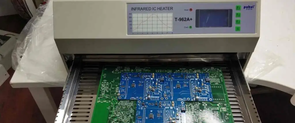
Soldering Using IR Reflow
A typical technique for the quick manufacturing of PCBs is IR reflow soldering. The solder paste, made of solder flux and solder, is applied to the essential parts of the circuit board during the procedure. There is a minor viscosity to the paste. Electrical components must stick to the board as a result of this.
The PCB goes through the oven while being reflow soldered. This solder paste melts as a result (reflow). Each circuit board passes through a cooling cycle after its oven stage. These electrical components are now permanently attached to the pcb board because the solder has set.
For a few reasons, reflow soldering can be frequently used in the manufacture of circuit boards. The oven technique, in particular, has a far higher soldering capability than the hand soldering. That capability permits the manufacturing of the circuit boards in a large volume very quickly.
Second, there has been number of improvements made to ir reflow soldering techniques throughout time. These developments have made it possible for reflow soldering to produce surface mount devices with soldering of the greatest quality.
HACR Procedure
To achieve uniform soldering throughout the board when employing the IR reflow method to solder the PCB assembly, a special reflow profile must be created. HACR procedure primarily utilizes hot air, which isn’t always an appropriate method for soldering.
The HACR profile is significantly influenced by the PCB’s thermal mass as well as the components present on it. In addition, the components’ color also affects the profile since darker colors absorb heat faster and readily than lighter or reflective colors.
These elements alter the pace at which heat is transferred from hot air immediately it circulates inside the oven.
Thermocouples are used on the test circuit assembly to measure the temperature change as it passes the oven during profiling. This approach has two shortcomings. The first disadvantage is that it takes time to complete the task because a specific temperature profile is required for uniformly proper soldering. A second problem is that if a limited run is involved, the buyer might not be ready to deliver the necessary test PCB assembly.
VPR Procedure
Vapor phase oven use the vapor layer that transfers the latent heat when it condenses, in contrast to HACR, which utilizes hot air for transferring heat into the PCB as well as its components since it moves through a system present on the conveyor belt. When a particular liquid is boiled at a temperature of 235 °C within the system, a vapor layer is produced, and the latent heat gotten from this vapor is transferred very effectively, causing components with differing thermal masses to reach this very same temperature simultaneously.
Early VPR oven models were not known since a lot of this vapor leaked out, making them harmful to both the user and the environment. Moreover, its IR reflow profile was fairly dependent on the temperature range and the volume of fluid inside the tank.
Only few batches of PCB assemblies could be soldered at once due to the need for manual handling when putting them inside the oven.
Current VPR ovens have a completely new design, with this enclosure recovering nearly all of the vapor medium. The manufacturers now handle PCB assemblies automatically, making it possible to precisely monitor and regulate its temperature profile.
VPR Soldering Process

Since all that is required to melt its solder is the introduction of sufficient heat, soldering first appears as a straightforward procedure. Whenever the system uses solder paste for soldering SMT boards, there are many more steps involved in the process.
A copper pad just on Circuit board as well as component leads must also warm up to a temperature just above the solder paste’s melting point in order for a solder joint to be considered successful. A chilly and unsuccessful joint arises from failing to accomplish this. Also, the components should not be overheated when applying heat because this could harm them. In contrast to other soldering methods, such as radiation, forced convection, or conduction via the soldering gun, this VPR process of soldering transmits heat from the condensing vapor.
The VP reflow machines operate in a very basic manner. This vapor stage fluid sits at room temp at the fluid tank’s bottom before being turned on.
The fluid is heated to boiling after being turned on at 235 °C, which is the average melting temperature of the lead-free solder pastes.
The ideal temperature necessary for melting the solder paste is 235 °C, hence VPR system manufacturers explicitly engineer their products to have a boiling point for a liquid in vapor phase at this temperature. The vapor produced by the boiling liquid is thick and has sufficient latent heat to be transferred to the circuit board assembly.
Vapor condenses present on the cold circuit board assembly as it enters the tank, transmitting the latent heat into the circuit board pads and components till they all reach the equivalent temperature like the vapor. The circuit board assembly cannot become too hot due to the system.
Conclusion
For IR reflow soldering, the solder paste, made of solder flux and solder, is applied to the essential parts of the circuit board during the procedure. Vapor phase type of reflow soldering is a quick and incredibly reliable technique that our company recommends for circuit board assemblies. The technique is appropriate and dependable for soldering SMT circuit boards with a variety of complicated components, including flip chips, QFTs, ceramic assemblies, and BGAs.