Printed Circuit Boards (PCBs) are the backbone of modern electronics, providing a compact and efficient platform for mounting and interconnecting electronic components. As technology advances and the demand for miniaturization grows, designers are constantly seeking innovative ways to optimize PCB designs. One such innovation is the use of embedded resistors, which offer numerous advantages over traditional surface-mount resistors.
This comprehensive guide will explore the world of embedded resistors in PCB design, covering everything from the basics to advanced techniques and considerations. We’ll delve into the benefits, design process, materials, manufacturing techniques, and best practices for incorporating embedded resistors into your PCB designs.
Understanding Embedded Resistors
What Are Embedded Resistors?
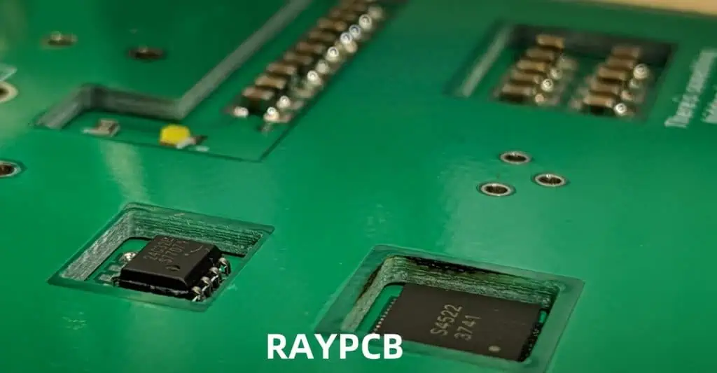
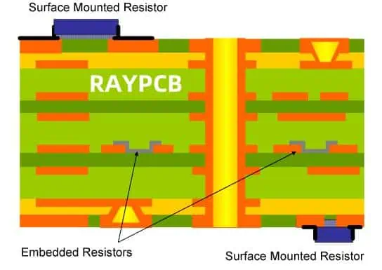
Embedded resistors are resistive elements that are integrated directly into the inner layers of a PCB, rather than being mounted on the surface. These resistors are formed using specialized resistive materials and manufacturing processes, becoming an integral part of the PCB structure.
Advantages of Embedded Resistors
Embedded resistors offer several significant advantages over traditional surface-mount resistors:
- Space-saving: By integrating resistors into the PCB layers, valuable surface area is freed up for other components or routing.
- Improved reliability: Embedded resistors are protected from environmental factors and mechanical stress, leading to increased durability.
- Enhanced electrical performance: Shorter connection paths reduce parasitic effects and improve signal integrity.
- Cost-effective for high-volume production: While initial setup costs may be higher, embedded resistors can be more economical in large-scale manufacturing.
- Improved thermal management: Embedded resistors distribute heat more evenly throughout the PCB.
Types of Embedded Resistors
There are several types of embedded resistors, each with its own characteristics and applications:
- Printed Resistors: Created by printing resistive ink or paste onto the PCB substrate.
- Plated Resistors: Formed by electroplating a resistive material onto the PCB.
- Thin-film Resistors: Deposited as a thin film of resistive material on the PCB surface.
- Thick-film Resistors: Similar to thin-film, but with a thicker layer of resistive material.
Designing Embedded Resistors
Design Considerations
When incorporating embedded resistors into your PCB design, several factors must be considered:
- Resistance value and tolerance
- Power dissipation
- Temperature coefficient of resistance (TCR)
- Frequency response
- Current-carrying capacity
- Available PCB real estate
- Manufacturing process compatibility
Design Process
The process of designing embedded resistors typically involves the following steps:
- Determine resistor requirements
- Select appropriate resistive material
- Calculate resistor dimensions
- Choose resistor location within PCB layers
- Design resistor terminations
- Verify design using simulation tools
- Create necessary documentation for manufacturing
Let’s explore each of these steps in detail.
1. Determine Resistor Requirements
Begin by clearly defining the electrical specifications for each embedded resistor:
- Resistance value and tolerance
- Maximum power dissipation
- Operating temperature range
- Frequency range (if applicable)
- Current rating
2. Select Appropriate Resistive Material
Choose a resistive material that best meets your design requirements. Common materials include:
| Material | Sheet Resistance Range (Ω/sq) | TCR (ppm/°C) | Typical Tolerance |
| NiCr | 10 – 1000 | ±50 to ±100 | ±5% to ±10% |
| TaN | 10 – 1000 | ±25 to ±50 | ±1% to ±5% |
| RuO2 | 10 – 10000 | ±50 to ±200 | ±5% to ±20% |
| Carbon | 10 – 1000000 | -200 to -600 | ±10% to ±30% |
3. Calculate Resistor Dimensions
Use the following formula to determine the dimensions of your embedded resistor:
R = (ρ * L) / (W * T)
Where:
- R: Resistance value (Ω)
- ρ: Resistivity of the material (Ω·m)
- L: Length of the resistor (m)
- W: Width of the resistor (m)
- T: Thickness of the resistive layer (m)
Adjust the length and width to achieve the desired resistance value while considering manufacturing limitations and available space.
4. Choose Resistor Location
Determine the optimal location for each embedded resistor within the PCB stack-up. Consider factors such as:
- Proximity to associated components
- Thermal management
- Signal integrity
- Layer availability
5. Design Resistor Terminations
Create appropriate terminations for the embedded resistors to ensure proper electrical connection and mechanical stability. Common termination methods include:
- Plated through-holes (PTH)
- Buried vias
- Surface pads
6. Verify Design Using Simulation Tools
Use PCB design and simulation software to verify the performance of your embedded resistors. Key aspects to simulate include:
- DC and AC performance
- Thermal behavior
- Signal integrity
- Electromagnetic compatibility (EMC)
7. Create Manufacturing Documentation
Prepare detailed documentation for the PCB manufacturer, including:
- PCB stack-up information
- Resistor material specifications
- Resistor dimensions and locations
- Termination details
- Test and verification requirements
Manufacturing Techniques for Embedded Resistors
Printed Resistor Process
- Screen printing: Resistive ink is applied through a patterned screen onto the PCB substrate.
- Photolithography: A photosensitive resistive material is applied, exposed, and developed to create the resistor pattern.
Plated Resistor Process
- Subtractive process: A resistive layer is plated over the entire board, then selectively etched to form resistors.
- Additive process: Resistive material is selectively plated onto pre-defined areas of the PCB.
Thin-film and Thick-film Processes
- Sputtering: Resistive material is deposited onto the PCB substrate using physical vapor deposition.
- Chemical vapor deposition (CVD): Resistive material is formed on the PCB through chemical reactions in a vapor phase.
Best Practices for Embedded Resistor Design
- Start with larger tolerances: Begin your design with wider tolerance ranges and tighten them as necessary during prototyping and testing.
- Consider thermal management: Design your PCB layout to efficiently dissipate heat generated by embedded resistors.
- Use standardized values: Whenever possible, use standard resistance values to simplify manufacturing and reduce costs.
- Implement proper terminations: Ensure that resistor terminations are designed for reliability and ease of testing.
- Account for parasitic effects: Consider the impact of parasitic capacitance and inductance when designing high-frequency circuits.
- Utilize design rules: Implement and follow design rules specific to embedded resistors to ensure manufacturability and reliability.
- Plan for testing and verification: Design your PCB with test points or structures that allow for easy verification of embedded resistor values.
Challenges and Limitations
While embedded resistors offer numerous advantages, they also come with some challenges and limitations:
- Limited resistance range: The available resistance values are typically more limited compared to discrete resistors.
- Trimming requirements: Some embedded resistors may require laser trimming to achieve precise resistance values, adding complexity to the manufacturing process.
- Design flexibility: Once embedded, resistors cannot be easily modified or replaced, limiting design flexibility.
- Initial cost: The setup and tooling costs for embedded resistor manufacturing can be higher than those for traditional surface-mount resistors.
- Thermal considerations: Heat dissipation can be more challenging with embedded resistors, requiring careful thermal management in high-power designs.
Future Trends in Embedded Resistor Technology
As PCB technology continues to evolve, several trends are emerging in the field of embedded resistors:
- Improved materials: Development of new resistive materials with better stability, lower TCR, and wider resistance ranges.
- Enhanced manufacturing processes: Advancements in printing and deposition technologies for more precise and reliable embedded resistors.
- Integration with other passive components: Combining embedded resistors with capacitors and inductors to create fully integrated passive networks.
- 3D printing: Exploration of additive manufacturing techniques for creating complex embedded resistor structures.
- Smart PCBs: Integration of embedded resistors with sensors and microcontrollers for self-monitoring and adaptive functionality.
Conclusion
Embedded resistors represent a significant advancement in PCB design, offering numerous benefits in terms of space savings, reliability, and performance. By understanding the design process, manufacturing techniques, and best practices outlined in this guide, PCB designers can effectively incorporate embedded resistors into their designs, pushing the boundaries of miniaturization and functionality in electronic devices.
As technology continues to evolve, embedded resistors will likely play an increasingly important role in the future of electronics, enabling more compact, efficient, and reliable designs across a wide range of applications.
Frequently Asked Questions (FAQ)
1. What is the typical tolerance range for embedded resistors?
Embedded resistors typically have tolerances ranging from ±1% to ±20%, depending on the material and manufacturing process used. Printed and plated resistors often have wider tolerances (±5% to ±20%), while thin-film resistors can achieve tighter tolerances (±1% to ±5%). It’s important to note that tighter tolerances generally come with higher manufacturing costs.
2. How do I choose between embedded resistors and surface-mount resistors for my PCB design?
The choice between embedded and surface-mount resistors depends on several factors:
- Space constraints: If board real estate is at a premium, embedded resistors can free up valuable surface area.
- Production volume: For high-volume production, embedded resistors can be more cost-effective despite higher initial setup costs.
- Electrical performance: If your design requires minimal parasitic effects or improved signal integrity, embedded resistors may be preferable.
- Design flexibility: If you anticipate frequent design changes or need the ability to easily replace components, surface-mount resistors offer greater flexibility.
- Resistance value range: If you need a wide range of precise resistance values, surface-mount resistors may be more suitable.
Consider these factors in the context of your specific design requirements to make the best choice.
3. Can embedded resistors be used in high-frequency applications?
Yes, embedded resistors can be used in high-frequency applications and often offer better performance than surface-mount resistors due to reduced parasitic effects. However, proper design considerations are crucial:
- Use materials with low dielectric loss for the PCB substrate.
- Minimize the length of resistor terminations to reduce inductance.
- Consider the skin effect at high frequencies when calculating resistor dimensions.
- Use electromagnetic simulation tools to verify performance and optimize layouts for high-frequency operation.
4. What are the key challenges in testing and verifying embedded resistors?
Testing and verifying embedded resistors can be challenging due to their integration within the PCB layers. Key challenges include:
- Limited physical access: Traditional probing methods may not be possible.
- Influence of surrounding circuitry: Adjacent traces and components can affect measurements.
- Accuracy of test equipment: High-precision equipment may be required for tight-tolerance resistors.
- Temperature effects: Thermal considerations during testing can impact resistance measurements.
To address these challenges, consider implementing dedicated test structures, using flying probe testers, or employing built-in self-test (BIST) circuitry in your design.
5. How do embedded resistors impact the overall reliability of a PCB?
Embedded resistors generally improve the overall reliability of a PCB in several ways:
- Protection from environmental factors: Being embedded within the PCB layers shields the resistors from moisture, dust, and other contaminants.
- Reduced mechanical stress: Embedded resistors are less susceptible to vibration and shock compared to surface-mounted components.
- Improved thermal management: Heat dissipation is more evenly distributed throughout the PCB.
- Fewer solder joints: Reducing the number of solder connections decreases potential failure points.
- Consistent performance: Embedded resistors maintain more stable characteristics over time due to their protected environment.
However, it’s important to note that proper design and manufacturing processes are crucial to realizing these reliability benefits. Poorly designed or manufactured embedded resistors can potentially lead to difficult-to-diagnose failures within the PCB structure.