In the ever-evolving world of electronics manufacturing, Printed Circuit Board (PCB) assembly techniques play a crucial role in determining the quality, reliability, and performance of electronic devices. Among these techniques, bottom filling technology has emerged as a game-changing approach, particularly for components with bottom terminations such as Ball Grid Arrays (BGAs), Land Grid Arrays (LGAs), and Quad Flat No-Leads (QFNs). This article delves into the application of bottom filling technology in PCB assembly, exploring its benefits, challenges, and best practices.
Understanding Bottom Filling Technology
What is Bottom Filling?
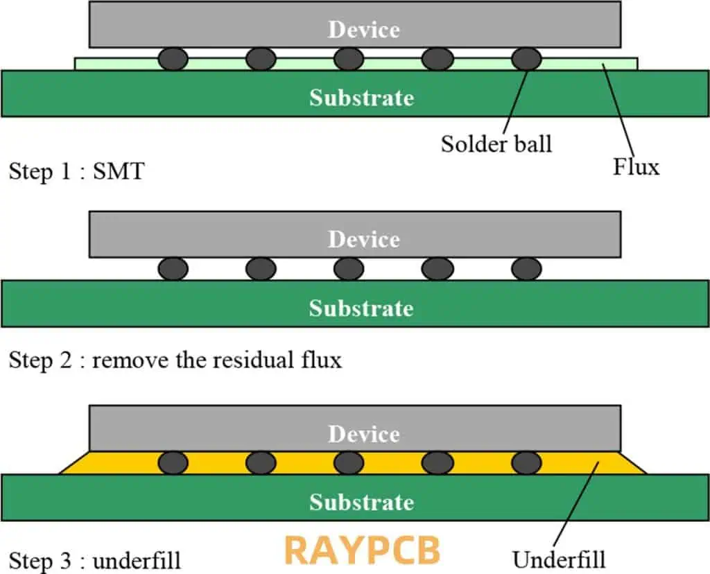
Bottom filling, also known as underfilling or capillary underfill, is a process used in PCB assembly to enhance the mechanical and thermal reliability of surface mount components. It involves dispensing a specially formulated epoxy material beneath a component after it has been soldered to the PCB.
The Need for Bottom Filling
As electronic devices become smaller and more complex, the demand for higher component density and improved reliability has increased. Bottom filling addresses several challenges associated with modern PCB assembly:
- Thermal stress management
- Mechanical shock resistance
- Enhanced solder joint reliability
- Improved moisture resistance
Types of Bottom Filling Materials
Capillary Flow Underfills
Capillary flow underfills rely on capillary action to flow beneath the component after dispensing.
Characteristics:
- Low viscosity
- Self-leveling properties
- Longer working time
No-Flow Underfills
No-flow underfills are applied before component placement and cure during the reflow soldering process.
Characteristics:
- Higher viscosity
- Shorter working time
- Integrated flux for soldering
Comparison of Underfill Types
| Characteristic | Capillary Flow Underfills | No-Flow Underfills |
| Application | Post-reflow | Pre-reflow |
| Viscosity | Low | High |
| Working Time | Longer | Shorter |
| Process Steps | More | Fewer |
| Flux Content | None | Integrated |
| Reworkability | Moderate | Difficult |
Bottom Filling Process
Step 1: Surface Preparation
Ensure the PCB surface and component undersides are clean and free from contaminants.
Step 2: Material Selection
Choose the appropriate underfill material based on:
- Component type and size
- PCB material and surface finish
- Environmental conditions
- Thermal requirements
Step 3: Dispensing
Dispensing Methods
- Needle dispensing
- Jetting
- Stencil printing (for no-flow underfills)
Dispensing Patterns
- L-shape
- U-shape
- I-shape
Step 4: Capillary Flow (for capillary underfills)
Allow time for the underfill to flow beneath the component through capillary action.
Step 5: Curing
Cure the underfill material according to the manufacturer’s specifications.
Benefits of Bottom Filling Technology

1. Enhanced Reliability
Bottom filling significantly improves the reliability of solder joints by:
- Distributing stress across a larger area
- Reducing thermal fatigue
- Minimizing the effects of CTE mismatch
2. Improved Thermal Management
Underfill materials often have better thermal conductivity than air, leading to:
- Enhanced heat dissipation
- Reduced thermal resistance
- Improved overall thermal performance
3. Increased Mechanical Strength
Bottom filling provides additional mechanical support, resulting in:
- Higher resistance to shock and vibration
- Reduced risk of component detachment
- Improved drop test performance
4. Moisture Protection
Underfill acts as a barrier against moisture, offering:
- Enhanced corrosion resistance
- Improved long-term reliability in humid environments
- Reduced risk of electrical shorts due to moisture ingress
5. Enabling Finer Pitch Components
By providing additional mechanical and thermal support, bottom filling allows for:
- Use of finer pitch components
- Higher component density
- More compact PCB designs
Challenges and Considerations
1. Process Control
Maintaining consistent underfill coverage and flow requires careful process control:
- Temperature management
- Dispense volume accuracy
- Flow time optimization
2. Material Selection
Choosing the right underfill material is critical:
- Compatibility with solder mask and flux residues
- Thermal expansion coefficient matching
- Curing temperature and time considerations
3. Reworkability
Underfilled components can be challenging to rework:
- Specialized rework equipment may be required
- Risk of PCB damage during underfill removal
- Increased time and cost for rework processes
4. Voiding
Air entrapment can lead to voids in the underfill:
- Reduced thermal and mechanical performance
- Potential reliability issues
- Need for careful process optimization to minimize voiding
5. Cost Considerations
Implementing bottom filling technology involves additional costs:
- Material costs
- Equipment investment
- Increased process time
- Potential yield impact during initial implementation
Best Practices for Bottom Filling Implementation
1. Design for Underfill
Consider underfill requirements during PCB design:
- Adequate clearance around components
- Proper pad and via design for underfill flow
- Thermal management considerations
2. Material Qualification
Thoroughly qualify underfill materials:
- Compatibility testing with PCB and component materials
- Reliability testing (thermal cycling, drop test, etc.)
- Shelf life and storage condition verification
3. Process Optimization
Develop and optimize the underfill process:
- Dispense pattern and volume optimization
- Flow and cure time characterization
- In-line inspection implementation
4. Equipment Selection
Choose appropriate dispensing and curing equipment:
- Precision dispensing systems
- Temperature-controlled stages
- Automated optical inspection (AOI) systems
5. Training and Documentation
Invest in operator training and create detailed process documentation:
- Standard operating procedures (SOPs)
- Visual aids for proper underfill application
- Troubleshooting guides
Future Trends in Bottom Filling Technology
1. Advanced Materials
Development of new underfill materials with:
- Improved thermal conductivity
- Faster curing times
- Enhanced reworkability
2. Automation and Industry 4.0 Integration
Increased automation in underfill processes:
- Inline underfill dispensing and curing
- Real-time process monitoring and adjustment
- Integration with MES and Industry 4.0 systems
3. Miniaturization Support
Underfill technologies adapted for increasingly miniaturized components:
- Ultra-fine pitch BGAs and CSPs
- 3D packaged devices
- Flexible and stretchable electronics
4. Sustainability Focus
Development of more environmentally friendly underfill solutions:
- Bio-based materials
- Reduced volatile organic compound (VOC) content
- Improved recyclability and end-of-life considerations
Case Studies: Success Stories in Bottom Filling Application
1. Automotive Electronics
Application of bottom filling in harsh automotive environments:
- Improved reliability in high-temperature underhood applications
- Enhanced vibration resistance for powertrain control modules
- Increased lifespan of safety-critical systems
2. Mobile Devices
Bottom filling enabling advancements in smartphone design:
- Support for ultra-thin package-on-package (PoP) configurations
- Improved drop test performance for consumer devices
- Enhanced heat dissipation in high-performance mobile processors
3. Aerospace and Defense
Bottom filling technology in mission-critical aerospace applications:
- Extreme temperature cycling resistance for satellite electronics
- Improved shock and vibration tolerance for military equipment
- Enhanced long-term reliability for avionics systems
Frequently Asked Questions (FAQ)
- Q: What types of components typically require bottom filling? A: Bottom filling is commonly used for components with bottom terminations, such as Ball Grid Arrays (BGAs), Land Grid Arrays (LGAs), Chip Scale Packages (CSPs), and Quad Flat No-Leads (QFNs). These components often have a high pin count and fine pitch, making them more susceptible to thermal and mechanical stresses.
- Q: How does bottom filling improve the reliability of PCB assemblies? A: Bottom filling enhances reliability by distributing stress across a larger area, reducing thermal fatigue, minimizing the effects of CTE mismatch, and providing additional mechanical support. This results in improved resistance to thermal cycling, shock, and vibration, as well as better protection against moisture ingress.
- Q: What are the main challenges in implementing bottom filling technology? A: The main challenges include process control (maintaining consistent underfill coverage and flow), material selection (ensuring compatibility and performance), reworkability (difficulty in removing underfilled components), voiding (air entrapment in the underfill), and cost considerations (additional materials, equipment, and process time).
- Q: How does bottom filling affect the thermal performance of a PCB assembly? A: Bottom filling generally improves thermal performance by enhancing heat dissipation. Underfill materials often have better thermal conductivity than air, reducing the thermal resistance between the component and the PCB. This can lead to lower operating temperatures and improved overall thermal management of the assembly.
- Q: Is it possible to rework underfilled components, and if so, how? A: While challenging, it is possible to rework underfilled components. The process typically involves carefully heating the underfill to soften it, then removing the component and underfill material. Specialized rework equipment and techniques are often required. The PCB pads must then be cleaned and prepared before a new component can be installed. Due to the complexity and potential for damage, rework of underfilled components should be approached with caution and performed by trained technicians.