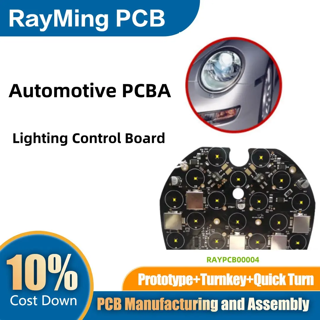
The automotive lighting control board is a critical component in modern vehicles, responsible for managing the operation of headlights, tail lights, turn signals, brake lights, and interior lighting systems. As vehicles become more advanced, the demand for sophisticated lighting control systems has grown, requiring precise design and manufacturing processes for the Printed Circuit Board Assembly (PCBA). The development of an automotive lighting control board involves a combination of electrical engineering, thermal management, and adherence to stringent automotive industry standards. This process ensures the reliability, safety, and performance of the lighting system under various operating conditions.
1. Design Phase
The design phase is the foundation of the PCBA development process. It begins with a thorough understanding of the vehicle’s lighting requirements, including functionality, power consumption, and communication protocols. Key considerations during this phase include:
- Schematic Design: The electrical schematic is created to map out the connections between components, such as microcontrollers, MOSFETs, LEDs, sensors, and communication modules. This schematic serves as the blueprint for the PCB layout.
- Component Selection: Choosing the right components is crucial for the board’s performance and durability. Components must be rated for the automotive environment, which involves exposure to extreme temperatures, vibrations, and moisture. For example, microcontrollers with built-in PWM (Pulse Width Modulation) capabilities are often used to control LED brightness, while high-efficiency MOSFETs are selected for power management.
- PCB Layout Design: The PCB layout is designed using specialized software, such as Altium Designer or Cadence OrCAD. Engineers must consider factors like signal integrity, thermal management, and electromagnetic compatibility (EMC). Proper placement of components and routing of traces are essential to minimize noise and ensure reliable operation. High-current paths, such as those for LED drivers, require wider traces to prevent overheating.
- Environmental Considerations: Automotive lighting control boards must withstand harsh conditions, including temperature extremes, humidity, and vibration. Conformal coating is often applied to the PCB to protect it from moisture and contaminants. Additionally, thermal vias and heat sinks are incorporated to dissipate heat generated by high-power components.
2. Prototyping and Testing
Once the design is finalized, a prototype of the control board is manufactured. Prototyping allows engineers to validate the design and identify any potential issues before mass production. Key steps in this phase include:
- Functional Testing: The prototype is tested to ensure it performs all required functions, such as controlling LED brightness, managing turn signals, and interfacing with the vehicle’s communication network (e.g., CAN bus). Any discrepancies between the expected and actual performance are addressed through design revisions.
- Environmental Testing: The prototype is subjected to environmental stress tests, including temperature cycling, humidity exposure, and vibration testing, to ensure it can withstand real-world operating conditions. These tests are conducted in accordance with automotive industry standards, such as AEC-Q100 for component reliability.
- EMC Testing: Electromagnetic compatibility testing is conducted to ensure the control board does not emit excessive electromagnetic interference (EMI) and is immune to external interference. This is critical for maintaining the reliability of the vehicle’s electronic systems.
3. Manufacturing Phase
After the prototype has been validated, the control board moves into the manufacturing phase. This phase involves several steps to transform the design into a fully functional PCBA:
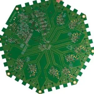
- PCB Fabrication: The bare PCB is manufactured using a multi-layer process that involves etching copper layers, drilling holes, and applying solder mask and silkscreen. High-quality materials are used to ensure the board’s durability and performance.
- Component Sourcing: Components are sourced from reliable suppliers to ensure consistency and quality. Automated systems are used to verify the authenticity and specifications of each component. Components must meet automotive-grade standards, such as AEC-Q100 for integrated circuits and AEC-Q200 for passive components.
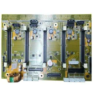
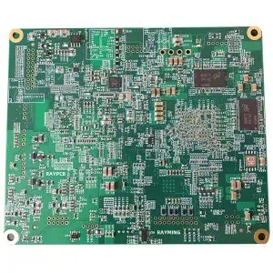
- Assembly: The PCB is populated with components using Surface Mount Technology (SMT) and through-hole technology. Automated pick-and-place machines are used for SMT components, while through-hole components are manually or automatically inserted.
- Soldering: Reflow soldering is used for SMT components, while wave soldering is employed for through-hole components. The soldering process is carefully controlled to ensure strong and reliable connections.
- Inspection and Quality Control: Automated Optical Inspection (AOI) and X-ray inspection are used to detect defects such as solder bridges, misaligned components, or insufficient solder. Functional testing is also performed to verify the board’s performance.
4. Final Assembly and Delivery
Once the PCBA passes all quality checks, it is integrated into the vehicle’s lighting system. The final assembly includes connecting the control board to the vehicle’s wiring harness, sensors, and actuators. The completed vehicle undergoes additional testing to ensure all systems work harmoniously before being shipped to customers.