Layer: 2 Layer PCB
Material: KB FR4
Surface Process: HASL-LF
Assembly Type: Full PCB Manufacturing ( PCB + Components + Assembly + Test )
Estimate PCB Assembly Cost, Pls send PCB File and Bom List to Sales@raypcb.com with Requirement.
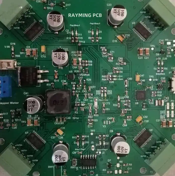
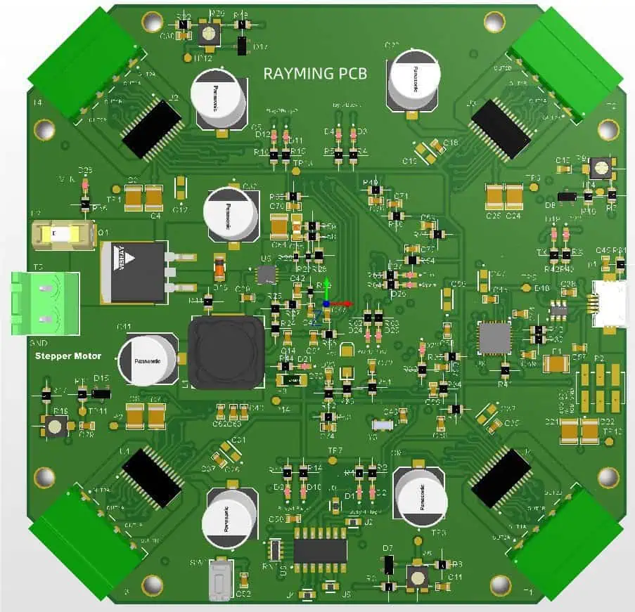
Designed a stepper motor controller for 4 motors. Communication protocol between ICs is SPI based on daisy chain. In order to avoid jitter among signals a new method is utilized. This project is also facilitated with USB connector for external used. Reverse protection is added in input voltage connector.
What is a Stepper Motor Controller PCB?
Stepper motor controller PCBs are essential components in various automated systems and precision machinery. These specialized printed circuit boards play a crucial role in managing the operation of stepper motors, which are widely used in applications requiring precise positioning and control. In this article, we’ll explore the intricacies of stepper motor controller PCBs, their functions, components, and applications.
Understanding Stepper Motors
Basic Principles
Stepper motors are electromechanical devices that convert electrical pulses into discrete mechanical movements. Unlike conventional motors, stepper motors rotate in fixed angular increments, or “steps,” providing excellent position control without the need for complex feedback systems.
Types of Stepper Motors
There are three main types of stepper motors:
- Variable Reluctance (VR)
- Permanent Magnet (PM)
- Hybrid (combines features of VR and PM)
Each type has its unique characteristics, influencing the design of the controller PCB.
Stepper Motor Controller PCB: Core Functions
1. Pulse Generation
The controller PCB generates precise electrical pulses that drive the stepper motor. These pulses determine the motor’s speed, direction, and position.
2. Current Regulation
Maintaining optimal current flow to the motor windings is crucial for efficient operation and preventing overheating. The controller PCB manages this through current chopping or other regulation techniques.
3. Microstepping
Advanced controller PCBs implement microstepping, which divides each full step into smaller increments, resulting in smoother motion and higher resolution.
4. Direction Control
The PCB determines the direction of motor rotation by controlling the sequence of energized windings.
5. Acceleration and Deceleration Profiles
Sophisticated controller PCBs can implement acceleration and deceleration profiles, allowing for smooth starts and stops, reducing mechanical stress on the system.
Key Components of a Stepper Motor Controller PCB
Microcontroller or DSP
The brain of the controller, responsible for executing control algorithms and generating step pulses.
Motor Driver IC
Handles the high current and voltage requirements of the motor windings, translating control signals into power outputs.
Power Management Circuitry
Regulates and distributes power to various components on the PCB.
Communication Interfaces
Enables the controller to receive commands from a host system (e.g., UART, SPI, I2C).
Protection Circuits
Safeguard the PCB and motor from overcurrent, overvoltage, and thermal issues.
Design Considerations for Stepper Motor Controller PCBs
1. Current Handling Capacity
The PCB must be designed to handle the maximum current required by the stepper motor without overheating or voltage drops.
2. Noise Reduction
Proper layout techniques and component selection are crucial to minimize electromagnetic interference (EMI) and ensure reliable operation.
3. Thermal Management
Efficient heat dissipation is essential, especially for high-power applications. This may involve the use of heat sinks, thermal vias, and careful component placement.
4. Signal Integrity
High-speed signals and sensitive analog circuits require careful routing and isolation to maintain signal integrity.
5. Size and Form Factor
The PCB design must consider space constraints and mounting requirements of the target application.
Applications of Stepper Motor Controller PCBs
Stepper motor controller PCBs find applications in a wide range of industries and devices:
| Industry | Applications |
|---|---|
| Manufacturing | CNC machines, 3D printers, pick-and-place machines |
| Robotics | Joint control, end effector positioning |
| Aerospace | Satellite positioning systems, aircraft control surfaces |
| Medical | Medical imaging equipment, drug delivery systems |
| Automotive | Headlight adjustment, throttle control |
| Consumer Electronics | Camera lens focus mechanisms, hard disk drives |
Advanced Features in Modern Stepper Motor Controller PCBs
Closed-Loop Control
Some advanced controller PCBs incorporate feedback mechanisms, such as encoders, to implement closed-loop control. This allows for:
- Error correction
- Stall detection
- Enhanced positioning accuracy
Multi-Axis Coordination
Complex motion control applications often require coordination between multiple stepper motors. Advanced controller PCBs can manage multiple axes simultaneously, enabling:
- Synchronized movements
- Interpolated motion paths
- Coordinated acceleration and deceleration
Networking Capabilities
Modern stepper motor controller PCBs often include networking features, allowing:
- Remote monitoring and control
- Integration with industrial IoT systems
- Firmware updates over the network
Challenges in Stepper Motor Controller PCB Design
1. EMI/EMC Compliance
Meeting electromagnetic compatibility standards while maintaining performance can be challenging, especially in noise-sensitive environments.
2. Thermal Management
High-current applications require careful thermal design to prevent overheating and ensure long-term reliability.
3. Cost Optimization
Balancing performance, features, and cost is an ongoing challenge in controller PCB design, especially for high-volume applications.
4. Miniaturization
As devices become smaller, fitting all necessary components and maintaining performance in a compact form factor becomes increasingly difficult.
Future Trends in Stepper Motor Controller PCBs
Integration of AI and Machine Learning
Future controller PCBs may incorporate AI algorithms for:
- Predictive maintenance
- Adaptive control
- Self-optimization
Enhanced Power Efficiency
Ongoing research in power electronics and control algorithms aims to improve the energy efficiency of stepper motor systems.
Increased Integration
We can expect to see more integrated solutions, combining the controller, driver, and even the motor itself into single packages.
Frequently Asked Questions
- Q: What’s the difference between a stepper motor controller PCB and a regular motor controller? A: A stepper motor controller PCB is specifically designed to generate precise step pulses and manage the unique requirements of stepper motors, such as microstepping and phase sequencing. Regular motor controllers typically don’t offer this level of precision and are designed for continuous rotation motors.
- Q: Can a single stepper motor controller PCB drive multiple motors? A: While some advanced controller PCBs can drive multiple motors, most are designed for a single motor. Driving multiple motors often requires separate power stages for each motor, even if controlled by a single microcontroller.
- Q: How do I choose the right stepper motor controller PCB for my application? A: Consider factors such as the motor’s voltage and current requirements, desired microstepping resolution, control interface (e.g., step/direction, serial), and any specific features needed for your application (e.g., closed-loop control, networking capabilities).
- Q: Are stepper motor controller PCBs programmable? A: Many modern stepper motor controller PCBs are programmable, allowing users to customize control algorithms, set motion profiles, and configure various parameters. The level of programmability varies depending on the specific controller and its intended application.
- Q: How do stepper motor controller PCBs handle heat dissipation? A: Stepper motor controller PCBs employ various heat dissipation techniques, including the use of heat sinks, thermal vias, copper pour areas, and strategic component placement. In high-power applications, additional cooling methods like fans or liquid cooling may be necessary.


