Sweeping robots, also known as robotic vacuum cleaners, have become increasingly popular in households worldwide. At the heart of these intelligent cleaning devices lies a sophisticated motherboard that controls all aspects of the robot’s functionality. This article delves into the intricacies of sweeping robot motherboard design and the subsequent PCB manufacturing and assembly process.
Motherboard Design
Microcontroller Selection
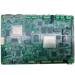
The centerpiece of any sweeping robot motherboard is its microcontroller. Engineers typically opt for powerful, yet energy-efficient microcontrollers capable of handling multiple tasks simultaneously. ARM Cortex-M series or similar processors are popular choices due to their balance of performance and power consumption.
Sensor Integration
Sweeping robots rely on a variety of sensors to navigate and clean effectively. The motherboard design must accommodate interfaces for:
- Infrared sensors for obstacle detection
- Cliff sensors to prevent falls
- Wheel encoders for odometry
- Gyroscopes and accelerometers for orientation and movement tracking
- Dirt detection sensors
Motor Control Circuits
The motherboard includes driver circuits for controlling multiple motors:
- Main brush motor
- Side brush motor(s)
- Wheel motors for movement
- Suction motor
These circuits often utilize H-bridge configurations or specialized motor driver ICs.
Power Management
Efficient power management is crucial for maximizing battery life. The motherboard incorporates:
- Battery management system (BMS) for Li-ion battery packs
- Voltage regulators for various components
- Power distribution network
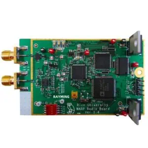
Wireless Connectivity
Modern sweeping robots often include Wi-Fi or Bluetooth modules for remote control and scheduling via smartphone apps. The motherboard design must account for antenna placement and signal integrity.
Memory and Storage
Sufficient RAM and flash memory are essential for storing mapping data, cleaning patterns, and firmware updates.
Expandability and Debugging
Design considerations often include expansion headers for additional features or debugging purposes during development and manufacturing.
PCB Manufacturing and Assembly
Once the motherboard design is finalized, the PCB manufacturing and assembly process begins.
PCB Design Software
Engineers use specialized EDA (Electronic Design Automation) software like Altium Designer, Eagle, or KiCad to create the PCB layout. This involves:
- Component placement optimization
- Routing of traces
- Power and ground plane design
- Design rule checks (DRC)
PCB Fabrication
The PCB fabrication process involves several steps:
- Creating a photomask from the PCB design files
- Applying photoresist to copper-clad laminate
- Exposing the board to UV light through the photomask
- Etching away unwanted copper
- Drilling holes for through-hole components and vias
- Applying solder mask and silkscreen
Component Sourcing
All necessary components are sourced, including:
- Microcontroller
- Passive components (resistors, capacitors)
- Connectors
- Sensor modules
- Power management ICs
Quality control at this stage is crucial to ensure all components meet specifications.
PCB Assembly
The assembly process typically involves surface-mount technology (SMT) for most components, with some through-hole components for certain connectors or power components.
- Solder Paste Application: A stencil is used to apply solder paste to the PCB pads.
- Component Placement: Pick-and-place machines accurately position SMT components onto the board.
- Reflow Soldering: The PCB passes through a reflow oven, melting the solder paste and securing components.
- Inspection: Automated Optical Inspection (AOI) systems check for misalignments or solder issues.
- Through-hole Component Insertion: Any through-hole components are manually or automatically inserted.
- Wave Soldering or Selective Soldering: Used to solder through-hole components.
- Final Inspection: Another round of inspection, often including X-ray inspection for hidden solder joints.
Functional Testing
Each assembled motherboard undergoes rigorous testing to ensure all components and subsystems function correctly. This includes:
- Power-on self-test
- Sensor functionality checks
- Motor control tests
- Wireless communication tests
- Battery charging and management system verification
Conformal Coating
Given the dusty environment in which sweeping robots operate, many manufacturers apply a conformal coating to the PCB. This thin polymer film protects against dust, moisture, and chemical contaminants.
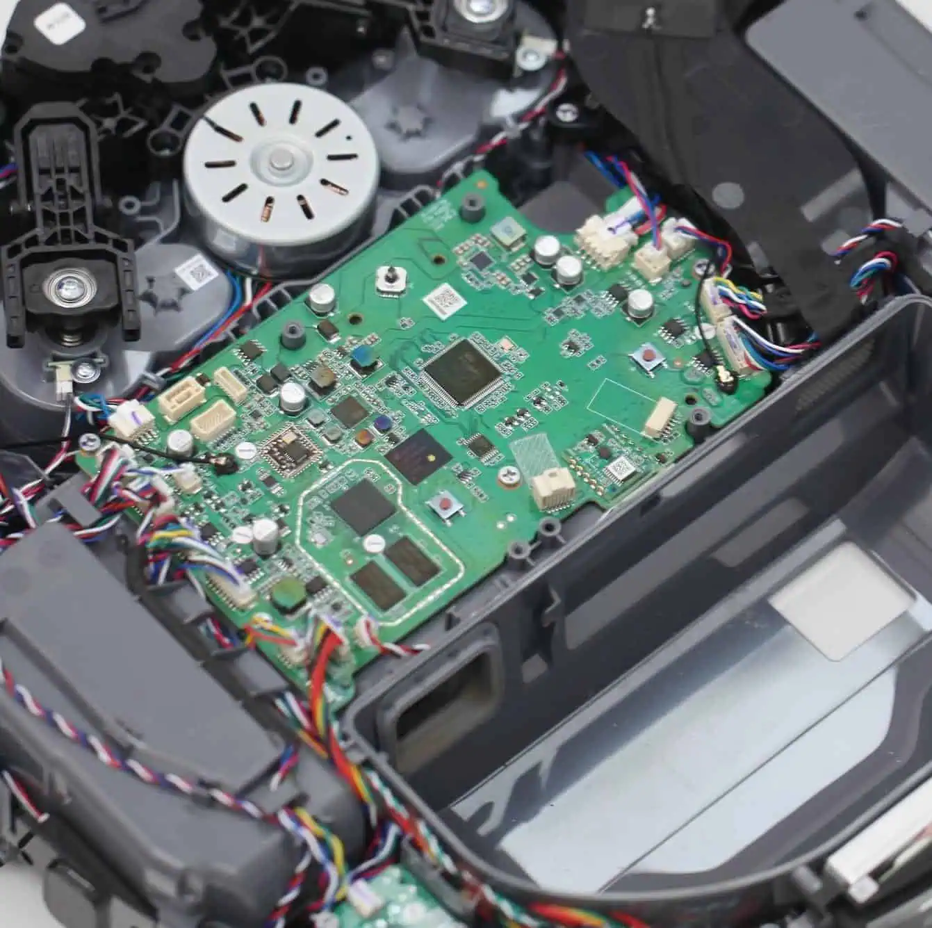
Integration and Final Assembly
The tested and coated motherboard is then integrated into the sweeping robot’s chassis, connected to motors, sensors, and the battery pack. Final assembly includes attaching brushes, wheels, and the outer casing.
Conclusion
The design and manufacturing of sweeping robot motherboards exemplify the convergence of various engineering disciplines. From intricate electronic design to precision manufacturing processes, every step is crucial in creating a reliable and efficient robotic vacuum cleaner. As technology advances, we can expect even more sophisticated designs, incorporating AI-driven navigation, advanced sensor fusion, and improved energy efficiency, further revolutionizing the world of home automation and cleaning.