POE Charging Equipment
Power over Ethernet (POE) charging equipment is a technology that allows network cables to carry electrical power alongside data. This technology is increasingly being used in various applications, including charging systems for electronic devices and powering network-connected equipment.
How POE Works
-
Power Sourcing Equipment (PSE): This is typically a network switch or a midspan device that injects power into the Ethernet cable.
-
Powered Device (PD): This is the equipment receiving power, such as IP cameras, VoIP phones, or in this case, charging stations.
-
Ethernet Cable: Standard Cat5e or Cat6 cables are used to carry both data and power.
-
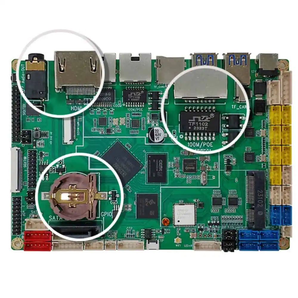
POE Standards: The most common standards are IEEE 802.3af (Type 1), 802.3at (Type 2), and 802.3bt (Types 3 and 4), providing up to 15.4W, 30W, 60W, and 100W of power respectively.
POE Charging Equipment Components
-
POE Controller: Manages power extraction from the Ethernet cable and controls the charging process.
-
DC-DC Converter: Converts the incoming POE voltage (usually 48V) to the required charging voltage for the device.
-
Charging Circuit: Regulates the charging current and voltage based on the connected device’s requirements.
-
Communication Interface: Allows the charging equipment to communicate with the connected device and the network for monitoring and control.
-
Safety Features: Includes over-voltage, over-current, and temperature protection circuits.
O2O Intelligent Self-Service Retail Terminal Equipment Control PCB
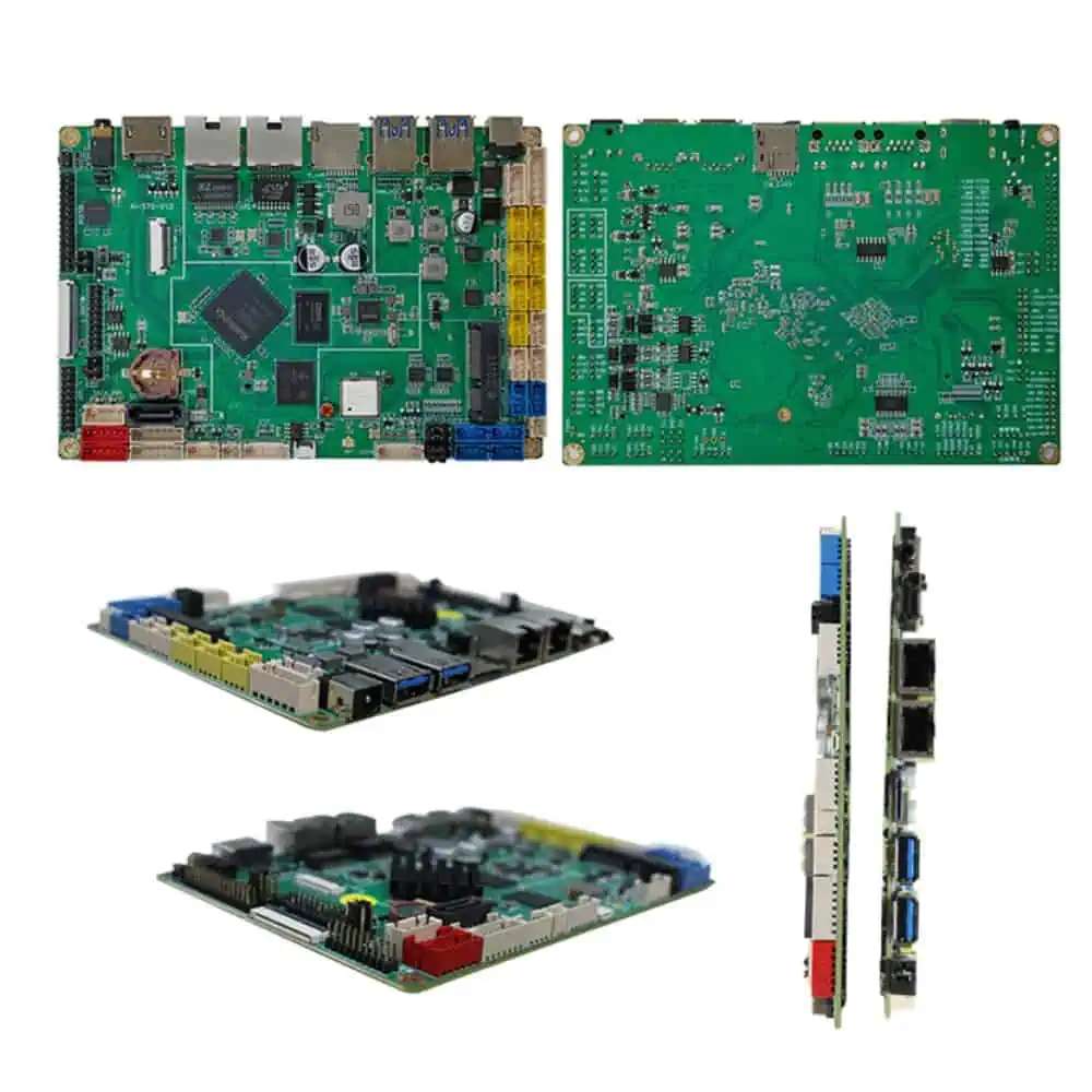
O2O (Online to Offline) intelligent self-service retail terminals are automated kiosks that bridge the gap between online and offline shopping experiences. These terminals often incorporate various technologies such as touch screens, payment systems, inventory management, and network connectivity.
Key Components of the Control PCB
-
Microcontroller/Processor: The brain of the system, typically a high-performance ARM or x86-based processor to handle complex operations and user interfaces.
-
Memory: Includes both RAM for active operations and non-volatile storage (e.g., eMMC or SSD) for the operating system and data.
-
Communication Interfaces:
- Ethernet: For network connectivity
- Wi-Fi: For wireless network access
- Bluetooth: For communication with user devices or maintenance tools
- 4G/5G Modem (optional): For cellular connectivity
-
Display Controller: Interfaces with the touch screen display, often supporting high-resolution graphics.
-
Payment System Interfaces:
- Card Reader Controller: For credit/debit card transactions
- NFC Controller: For contactless payments
- Cash Handling Interface: For machines that accept and dispense cash
-
Peripheral Controllers:
- USB Host: For connecting additional devices like barcode scanners or printers
- Serial Ports: For legacy device support
- GPIO: For various sensors and actuators
-
Power Management:
- Voltage Regulators: To provide appropriate power to all components
- Battery Backup (optional): For uninterrupted operation during power outages
- Power Monitoring: To ensure stable operation and protect against power anomalies
-
Real-Time Clock: To maintain accurate time for transactions and system operations
-
Security Features:
- Secure Element: For storing encryption keys and processing sensitive information
- Tamper Detection: To alert in case of unauthorized access attempts
-
Environmental Sensors:
- Temperature Sensor: To monitor and control the internal temperature
- Humidity Sensor: To protect against moisture in certain environments
-
Audio Subsystem:
- Audio Codec: For processing audio signals
- Amplifier: To drive speakers for user feedback and instructions
-
Expansion Interfaces:
- PCIe: For adding high-speed peripherals or custom modules
- I2C, SPI: For interfacing with various sensors and small displays
PCB Design Considerations
-
Layer Stack-up: Typically a multi-layer board (6-8 layers) to accommodate complex routing and proper power/ground planes.
-
Signal Integrity: Careful routing of high-speed signals with proper impedance control and minimal crosstalk.
-
Power Integrity: Proper decoupling and power plane design to ensure clean power delivery to all components.
-
Thermal Management: Strategic component placement and the use of thermal vias and copper pours to manage heat dissipation.
-
EMI/EMC Considerations: Proper grounding, shielding, and component placement to minimize electromagnetic interference.
-
Modular Design: Consider dividing the PCB into functional modules for easier testing, maintenance, and future upgrades.
-
Testability: Incorporate test points and debug interfaces for easier troubleshooting and quality control.
-
Reliability: Use of high-quality components and design practices to ensure long-term operation in various environmental conditions.
-
Certification Requirements: Design with relevant certifications in mind (e.g., UL, CE, FCC) to ease the approval process.
The control PCB for an O2O intelligent self-service retail terminal is a complex system that integrates various technologies to provide a seamless user experience. It requires careful design consideration to ensure reliability, performance, and ease of maintenance in a retail environment.