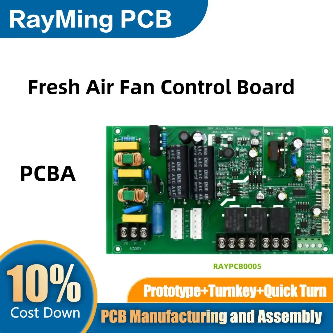
The fresh air fan control board is a critical component in modern ventilation systems, responsible for regulating the operation of fans that circulate fresh air into indoor spaces. These systems are commonly used in residential, commercial, and industrial settings to improve air quality, control humidity, and maintain comfortable indoor environments. The design and manufacturing of the Printed Circuit Board Assembly (PCBA) for a fresh air fan control board require a combination of electrical engineering expertise, thermal management, and adherence to industry standards. This process ensures the reliability, efficiency, and longevity of the ventilation system.
1. Design Phase
The design phase is the foundation of the PCBA development process. It begins with a thorough understanding of the fresh air fan system’s requirements, including fan speed control, airflow monitoring, and integration with sensors and user interfaces. Key considerations during this phase include:

- Schematic Design: The electrical schematic is created to map out the connections between components, such as microcontrollers, motor drivers, sensors, and communication modules. This schematic serves as the blueprint for the PCB layout.
- Component Selection: Choosing the right components is crucial for the board’s performance and durability. Components must be rated for the operating environment, which may involve exposure to dust, humidity, and temperature fluctuations. For example, microcontrollers with built-in PWM (Pulse Width Modulation) capabilities are often used to control fan speed, while Hall-effect sensors are selected for monitoring fan rotation.
- PCB Layout Design: The PCB layout is designed using specialized software, such as Altium Designer or Eagle. Engineers must consider factors like signal integrity, thermal management, and electromagnetic compatibility (EMC). Proper placement of components and routing of traces are essential to minimize noise and ensure reliable operation. High-current paths, such as those for motor drivers, require wider traces to prevent overheating.
- Environmental Considerations: Fresh air fan control boards must withstand various environmental conditions, including dust, humidity, and temperature extremes. Conformal coating is often applied to the PCB to protect it from moisture and contaminants. Additionally, thermal vias and heat sinks are incorporated to dissipate heat generated by high-power components.
2. Prototyping and Testing
Once the design is finalized, a prototype of the control board is manufactured. Prototyping allows engineers to validate the design and identify any potential issues before mass production. Key steps in this phase include:
- Functional Testing: The prototype is tested to ensure it performs all required functions, such as controlling fan speed, monitoring airflow, and interfacing with sensors and user interfaces. Any discrepancies between the expected and actual performance are addressed through design revisions.
- Environmental Testing: The prototype is subjected to environmental stress tests, including temperature cycling, humidity exposure, and vibration testing, to ensure it can withstand real-world operating conditions. These tests are conducted in accordance with industry standards, such as IP ratings for dust and moisture protection.
- EMC Testing: Electromagnetic compatibility testing is conducted to ensure the control board does not emit excessive electromagnetic interference (EMI) and is immune to external interference. This is critical for maintaining the reliability of the ventilation system and other electronic devices in the vicinity.
3. Manufacturing Phase
After the prototype has been validated, the control board moves into the manufacturing phase. This phase involves several steps to transform the design into a fully functional PCBA:
- PCB Fabrication: The bare PCB is manufactured using a multi-layer process that involves etching copper layers, drilling holes, and applying solder mask and silkscreen. High-quality materials are used to ensure the board’s durability and performance.
- Component Sourcing: Components are sourced from reliable suppliers to ensure consistency and quality. Automated systems are used to verify the authenticity and specifications of each component. Components must meet industry standards for reliability and performance.
- Assembly: The PCB is populated with components using Surface Mount Technology (SMT) and through-hole technology. Automated pick-and-place machines are used for SMT components, while through-hole components are manually or automatically inserted.
- Soldering: Reflow soldering is used for SMT components, while wave soldering is employed for through-hole components. The soldering process is carefully controlled to ensure strong and reliable connections.
- Inspection and Quality Control: Automated Optical Inspection (AOI) and X-ray inspection are used to detect defects such as solder bridges, misaligned components, or insufficient solder. Functional testing is also performed to verify the board’s performance.
4. Final Assembly and Delivery
Once the PCBA passes all quality checks, it is integrated into the fresh air fan system. The final assembly includes connecting the control board to the fan motor, sensors, and user interface. The completed system undergoes additional testing to ensure all components work harmoniously before being shipped to customers.