Here’s a brief overview of the process export gerber files from protel 99se:

Generating Gerber Files
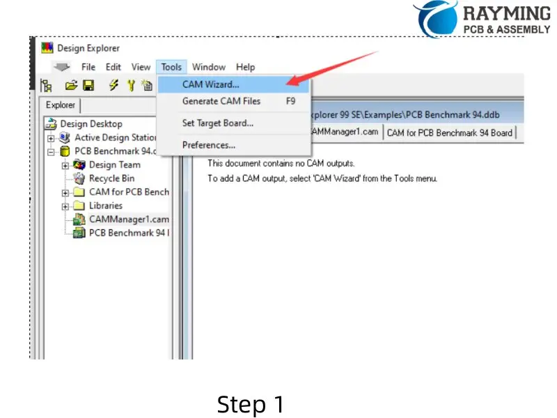
- Open your PCB project in Protel 99se.
- Select
Tools > CAM Wizardfrom the menu bar.
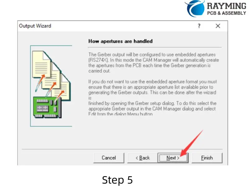
3. Follow these steps in the CAM Wizard:
- Click “Next” on the first screen.
- Select “Generate Gerber files” and click “Next”.
- Name your Gerber files as desired and click “Next”.
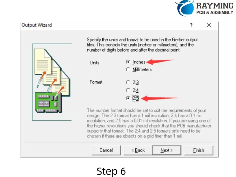
- For units, select “Inches” (default).
- Choose the appropriate format (Bittele supports the highest resolution, so 2.5 is recommended).
- Click “Next”.
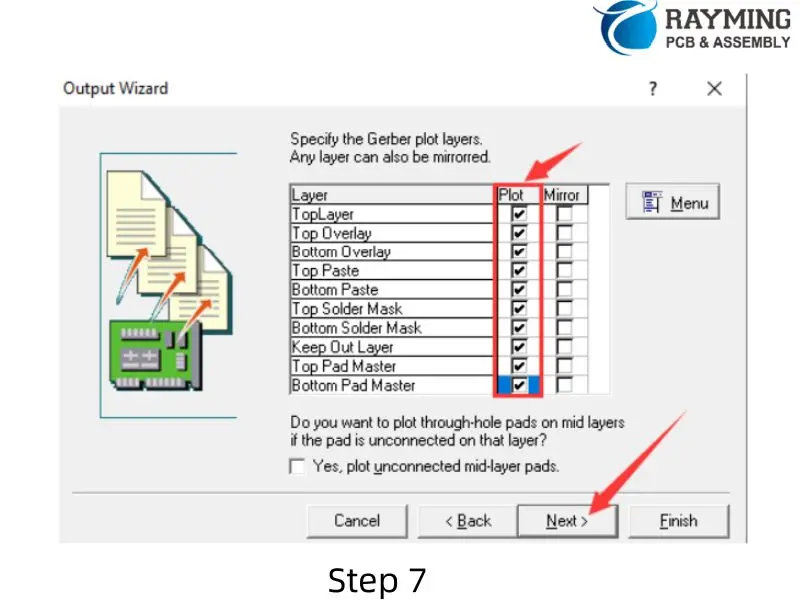
- On the next screen, select all options under “Plot”.
- Ensure all options under “Mirror” are unselected to avoid producing upside-down board layers.
- Click “Next”.
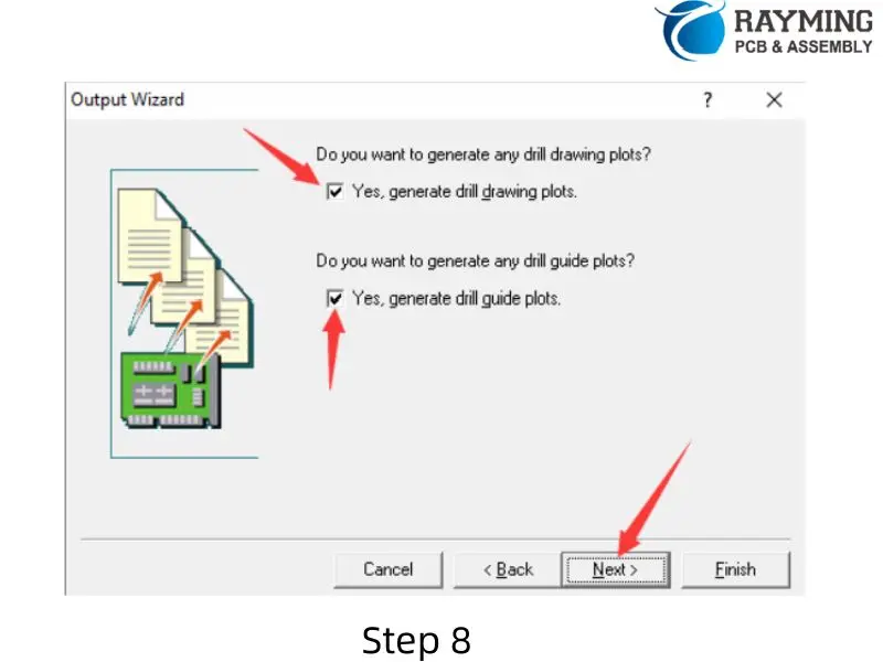
- On the following screen, leave the default boxes checked and click “Next”.
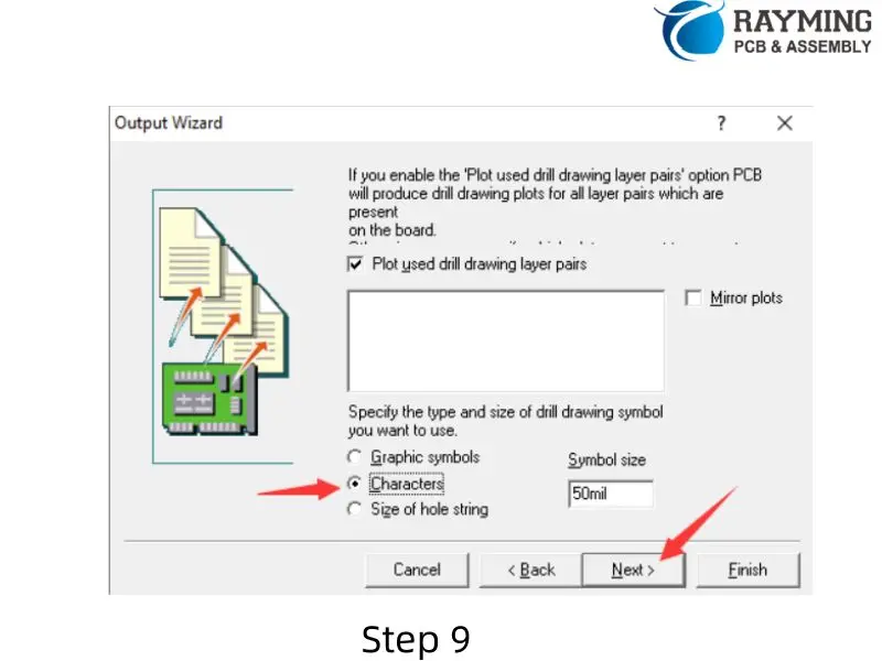
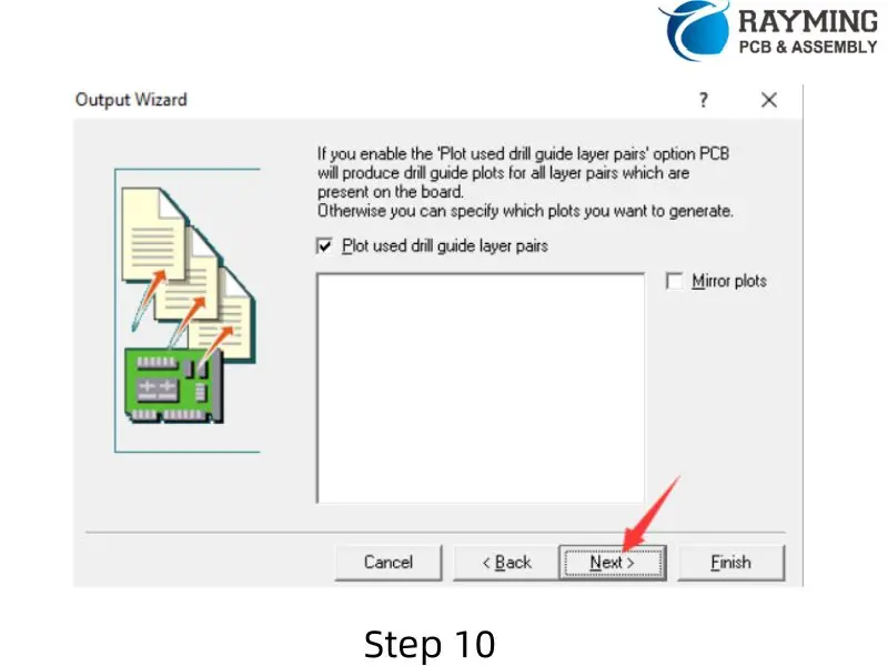
- Select “Characters” and leave the rest of the options as their default values.
- Click “Next” three more times, then click “Finish”.


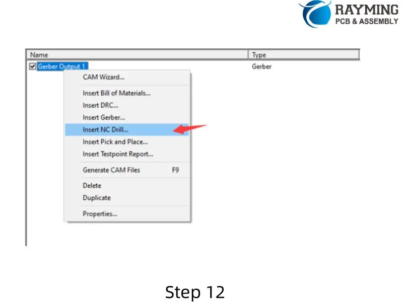
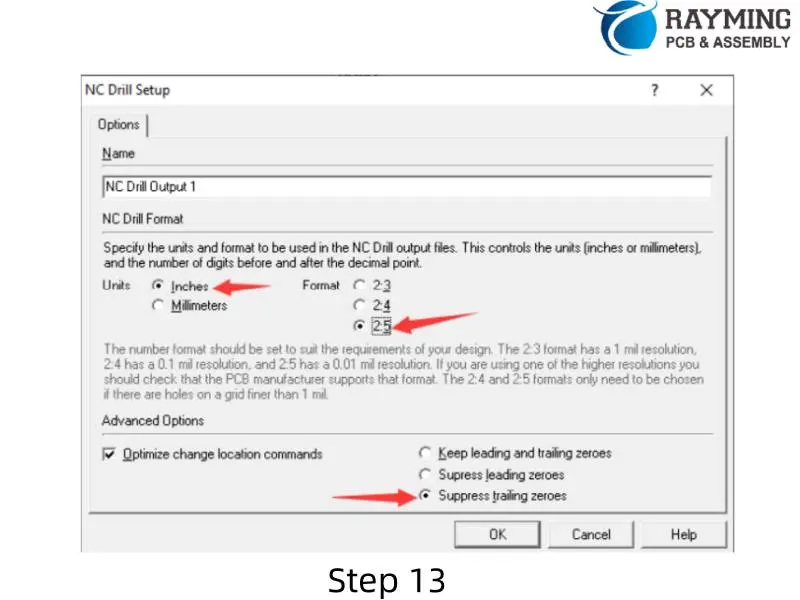
Generating Drill Files
- Right-click in the workspace and select “Insert NC Drill…”.
- In the pop-up menu:
- Set units to “Inches” (default).
- Change the format to 2.5.
- Keep “Optimize change location commands” checked.
- Check “Suppress trailing zeroes”.
- Click “OK”.
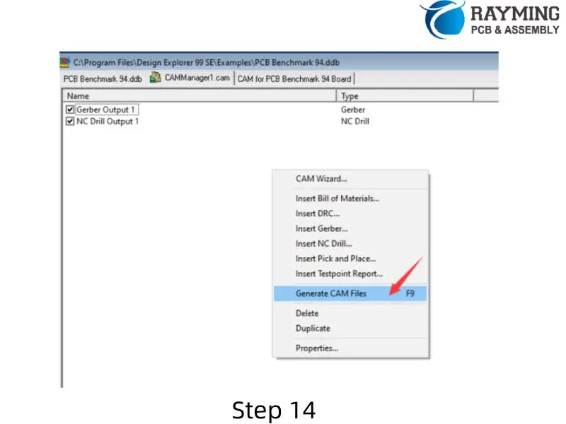
Exporting Gerber and Drill Files
- Right-click in the workspace and select “Generate CAM files”.
- A “CAM for (file name)” folder will be created in your catalog.
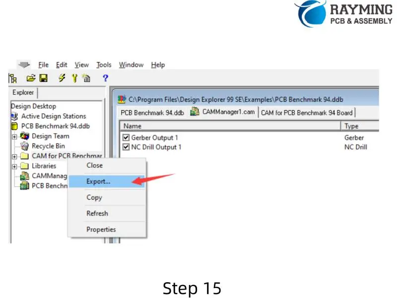
- Right-click on the created folder and choose “Export”.
- Select the destination where you want to export your files.
- Once completed, you will find your generated Gerber and drill files in the exported folder.
Important Notes
- When selecting the format (step 3.5 in Generating Gerber Files), choose based on your design requirements. 2.5 is recommended for highest resolution.
- Ensure that no options under “Mirror” are selected to avoid producing upside-down board layers.
- Double-check that all necessary layers are selected for plotting to ensure a complete set of Gerber files.