
RAYPCB · ENGINEERING REFERENCE
FR4 Thermal Conductivity: Direction, Copper & Data-Sheet Context
Read FR4 thermal data with the exact grade, direction and measurement context. Compare a laminate property with the copper-bearing board you actually intend to build.
Original engineering guidance · References checked September 29, 2026
FR4 thermal conductivity needs a grade and a direction
FR4 thermal conductivity is not one universal property value for every glass-reinforced epoxy board. The exact resin system, reinforcement, construction, direction and test context matter. A laminate data-sheet value also differs from an effective property assigned to a multilayer board containing patterned copper, vias and components. Start by deciding which of those objects the thermal model is supposed to represent.
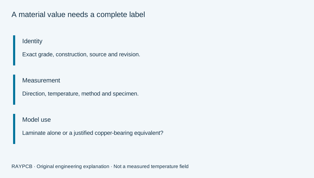
For a practical design, record the exact grade and manufacturer, the published conductivity, its units, the measurement method and any stated direction and temperature. Leave an unstated condition unresolved instead of inferring it from a familiar number. This disciplined record is more useful than a generic “FR4 k” field that later becomes difficult to justify.
This page addresses thermal-data interpretation. The FR4 PCB guide owns the broader material and manufacturing discussion, while the PCB thermal design guide connects material inputs to heat paths, interfaces and prototype evidence. Keeping these tasks separate helps you move from a material record to a usable engineering decision.
Published examples are examples, not a category specification
The official Isola product pages for 370HR and FR408HR each list thermal conductivity of 0.4 W/(m K), with ASTM E1952 shown as the method. These are two identifiable published records checked for this guide. They do not prove that every FR4 laminate has the same conductivity or that the effective property of a copper-bearing PCB equals that value.
| Published material example | Listed conductivity | Listed method | What still needs context |
|---|---|---|---|
| Isola 370HR | 0.4 W/(m K) | ASTM E1952 | Applicable direction, temperature, construction and source revision |
| Isola FR408HR | 0.4 W/(m K) | ASTM E1952 | Applicable direction, temperature, construction and source revision |
Consult the original 370HR material record and FR408HR material record when selecting inputs. Where the displayed property row does not state direction or temperature, obtain the applicable full data and supplier clarification. The table deliberately does not fill those gaps with guessed conditions.
Thermal conductivity is also different from Tg. Glass-transition behavior concerns changes in the resin's response around a temperature range; it does not directly specify how efficiently the material conducts heat. Selecting a higher-Tg laminate can address a particular thermal-exposure requirement without automatically providing the heat-spreading improvement that a designer expected from the word “thermal.”
Through-thickness and in-plane paths answer different questions
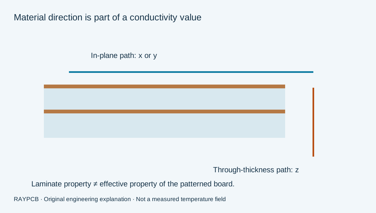
A board model often distinguishes x and y directions within the plane from z through the thickness. Heat leaving a device into a buried plane can involve both through-thickness transport and lateral spreading. An isotropic approximation assigns the same conductivity in all directions; an anisotropic model permits different values. The choice should follow the evidence and the engineering question, not a software default left unexplained.
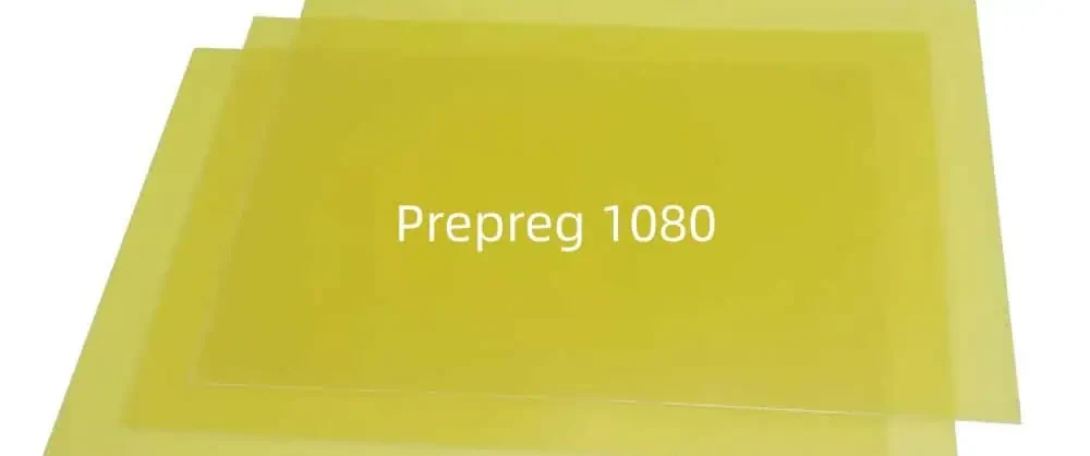
Glass reinforcement and resin arrangement make the material construction relevant to that decision. However, a photograph of glass fabric or a familiar glass-style designation does not provide a complete directional conductivity set. Nor does a prepreg designation alone determine the final cured dielectric thickness. Resin content, pressing and the approved stackup need to be considered separately when converting a material property into a layer resistance.
If a proposed heat path is through the board, a conductivity measured in a different direction should be flagged rather than silently substituted. If the direction is unknown, use sensitivity cases only with explicit assumptions and keep the unresolved question in the release record. A solver accepting the number is not evidence that the number represents the intended specimen.
A laminate property is not the effective board property
Copper patterns can make a completed board behave very differently from an unpatterned laminate specimen. A continuous plane, sparse traces and isolated copper islands do not provide the same lateral paths. Plane clearances, necks and cutouts can interrupt conduction. Their importance depends on where heat enters and where it can leave the assembly.
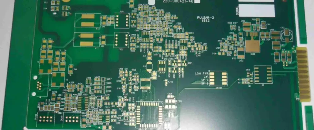
A homogeneous effective material can be useful when the model's length scale and purpose justify it. Document how copper coverage, layer locations and directional behavior were represented. Simple volume-weighted averages can be poor descriptions of a path containing series insulation or disconnected metal; the same average cannot automatically represent both in-plane and through-thickness behavior.
Likewise, plated through holes or filled vias add local geometry that may require explicit treatment. Review the thermal via design and assembly guide before assigning an improved effective property to the whole board. A via count without finished construction, location and plane attachments is not enough to establish the thermal contribution of the array.
Compare two material records without hiding missing conditions
Enter two named records, their conductivity values, direction, temperature and measurement-method references. The comparison worksheet checks whether the entered directions and temperatures match and whether the method descriptions are consistent. Enter “Not stated” for an unavailable temperature or method rather than inventing one. It withholds a conductivity ratio when those basic conditions remain unresolved or differ. This is a data-review aid, not a certification of equivalence.
RAYPCB ENGINEERING
Thermal DesignFR4 thermal data comparability worksheet
Loading FR4 thermal data comparability worksheet…
Matching labels do not prove that two specimens or test procedures were identical. Review grade revision, conditioning, density or construction information where relevant, and check whether typical values or guaranteed requirements are being compared. The worksheet's purpose is to make these distinctions visible before someone ranks two materials using an incomplete spreadsheet.
The illustrative example intentionally leaves one direction unstated. It demonstrates why a missing condition should remain visible rather than producing a confident ranking. For project work, replace every example field and retain the source reference. Downloaded records remain local until you choose to attach them; the page does not upload a supplier data sheet or populate a quotation form automatically.
Connect a valid conductivity input to the layer geometry
Suppose a hypothetical uniform layer is 0.2 mm thick, has conductivity 0.4 W/(m K) in the modeled direction and carries heat through 100 mm². The ideal one-dimensional resistance is 5 K/W. This is a calculation example using stated assumptions, not a claim that a particular complete FR4 board has 5 K/W resistance.
Halving thickness would halve that layer term if area and conductivity remained unchanged. Doubling an actually active area would also halve it in the same model. Neither operation proves that the required electrical insulation, impedance, mechanical strength or assembly constraints remain satisfied. Thermal changes must be reviewed within the approved construction rather than applied independently to one equation.
Use the PCB thermal resistance worksheet to retain individual layer terms and their shared-area assumption. The separate conductivity versus resistance explanation is useful when a material proposal quotes a better k value but changes thickness or contact geometry at the same time.
Decide whether to improve the path or change material family
If local spreading or board-to-housing contact dominates the temperature rise, changing the resin system may not address the bottleneck. A continuous copper path, a better-defined interface or relocation of a heat source may deserve investigation first. Each option has electrical and manufacturing consequences, so compare complete candidate constructions rather than isolated properties.
Where an insulating dielectric over a metal base is appropriate, the metal-core PCB guide provides a different construction route. It is not a universal replacement for a multilayer FR4 design: routing, grounding, insulation, mechanical fit and assembly requirements must still be reconciled. A thermal advantage under one arrangement does not settle those other requirements.
For a board with multiple concentrated sources, retain the material records in a thermal simulation input brief. Document whether the model resolves copper and vias or uses an equivalent region. This makes it possible for another engineer to understand which predictions are supported and which depend on simplifications that still require correlation.
Ask for evidence that matches the planned construction
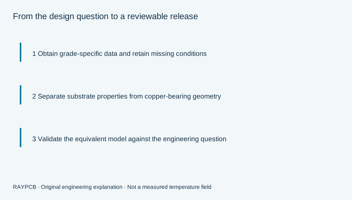
For PCB manufacturing, supply the approved stackup, exact material or substitution rules, finished copper requirements and the thermal purpose of critical features. Specify which thickness is controlled and how it relates to the thermal model. Avoid asking a fabricator to guarantee a product operating temperature based solely on a material conductivity entry.
If alternate materials are allowed, define the evidence needed for comparison before procurement substitutes a grade. Electrical properties, thermal exposure, mechanical behavior and process compatibility may remain essential even when the immediate discussion concerns conductivity. Record who approves the substitution and whether the thermal analysis must be rerun for the revised construction.
A useful prototype plan measures named locations under a known load and installed boundary condition. Preserve the material revision and actual build details with that record. If model and measurement disagree, inspect both the heat path and the measurement setup before adjusting a conductivity value merely to force agreement. Calibration against one test is not independent validation under a second condition.
You can send a material-data question with the stackup without completing the comparison tool. Include the source pages or documents you are using, the missing conditions and the design choice that depends on the answer. That context helps turn a broad request for “better thermal FR4” into a specific reviewable requirement.
FR4 thermal data questions
Can I use 0.4 W/mK for any FR4 PCB?
No. The cited value belongs to specific published material records. Verify the grade, direction and conditions needed by your model. A complete board with copper and vias also needs a representation of those features, rather than a blind substitution of a laminate value.
Does more copper always make the effective conductivity uniform?
No. Copper location, continuity, connections and direction matter. A board can spread heat efficiently along one region while remaining limited across an insulating layer. Effective properties should describe the intended modeling scale and should be checked against the paths of interest.
Is Tg a measure of heat removal?
No. Tg and conductivity describe different material behavior. Selecting a grade for thermal exposure or dimensional stability does not by itself establish a lower resistance between a device and its heat sink. Keep those requirements separate in the material comparison.
Why does the worksheet withhold a ratio?
It avoids ranking records whose entered direction, temperature, method or evidence basis does not support a like-for-like comparison. Resolve the missing context or retain the two records as separate assumptions. A blank ranking is more informative than a precise ratio with an unacknowledged mismatch.
Bring the heat path and manufacturing requirements together
Send the board revision, construction, quantity and the thermal design question you need reviewed. Identify unresolved requirements so the response can address them.
Send requirements for reviewOptional: attach the downloaded worksheet manually. This guidance does not certify a design, approve a shipment or replace the applicable authorized standards.