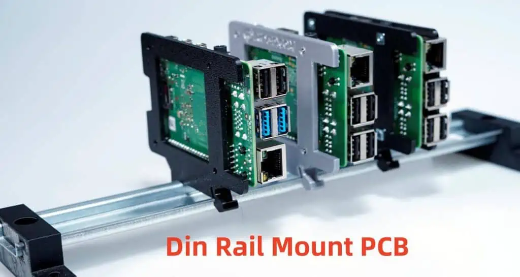
A DIN rail mount PCB (printed circuit board) is a circuit board designed to snap onto a DIN rail for easy installation and removal in industrial control panels or automation equipment.
DIN rail refers to a standard metal rail for mounting circuit breakers, I/O modules, power supplies, and other devices commonly used in the automation industry. The rail is 35 mm wide and conforms to DIN EN 50022 standards established by the Deutsche Institut für Normung (German Institute for Standardization).
Key Features of Din Rail Mount PCBs
- Designed with locking clips, hooks, or spring clips to securely attach the PCB to the DIN rail
- Compact size to fit standard DIN rail widths
- Connectors aligned to easily wire with other DIN rail components
- Durable construction for vibrating machinery environments
- Facilitates easy installation, access, and replacement of components
- Promotes modular flexibility, customization
Applications of Din Rail Mount PCB Assemblies
Din rail mount PCB assemblies are ubiquitous across industrial automation settings:
- Programmable logic controllers (PLCs)
- Human machine interfaces (HMIs)
- Motor drives and controllers
- Sensors (proximity, photoelectric)
- Timers and counters
- Power supplies
- Relays
- Terminal blocks and fuse holders
They provide an integrated, space-optimizing solution for control panels.
Construction of Din Rail Mount Printed Circuit Boards
Specialized PCBs are designed and manufactured to integrate with standard DIN rail brackets. Several din rail mounting methods secure the board firmly onto the rail.
Board Design
The PCB layout differs from traditional Eurocard formats. Key elements:
- Compact length and height dimensions
- Slotted mounting holes, edge cutouts, or specialized connectors to lock onto DIN rail
- Components only installed on one side
- High-density interconnects
DIN Rail Mounting Methods
There are several techniques to mount the PCB onto rails securely, while still enabling relatively easy install and de-installation:
1. Spring Loaded Clips
- Plastic or metal spring clips fix to the PCB edge
- Clips snap into position when the board is pushed onto the rail
- Release buttons allow technicians to dismount the board with light force
{{Image-Springclipdinpcb.jpg|Spring clip DIN rail PCB}}
2. PCB Cutouts and Hooks
- Rectangular edge slots or V-shaped notches designed into PCB
- Cutouts slip right over the top lip of DIN rail
- Special hooks, caps, or tabs lock it into place underneath
{{Image-Cutoutdinpcb.jpg|Cutout DIN rail PCB}}
3. Bolted Brackets
- Low-profile aluminum brackets secure to PCB bottom side with bolts
- Brackets hook over one edge of DIN rail
- Allow boards to cantilever off the rail surface
Layout Guidelines for Din Rail Mount Printed Circuit Boards
Proper PCB layout is critical generating a functional, field-reliable din rail mount board.
Component Placement
- Keep height under 4” to fit enclosures
- Ensure width matches DIN rail dimensions
- Place tall components parallel with height
- Arrange high-density areas over supported sections
Connector Positioning
- Align ports consecutive to terminal wiring
- Put connectors along the long side for accessibility
- Make ports facing outwards for cable insertion
- Include marker symbols for polarity and pin 1 labels
Heat Management
- Use thermal relief cutouts or copper openings around heat-sensitive parts
- Incorporate generous spacing around high-power components
- Locate heat sinks underneath hot devices
- Add ventilation holes above ventilation channels
Mechanical Reinforcement
- Avoid thin board sections prone to vibration issues
- Incorporate corner gussets or ribs to strengthen weak geometric shapes
- Install stiffeners, standoffs or metal backing around heavy devices
- Use conformal coating to harden board against dust and moisture
By incorporating these design practices, PCB developers mitigate field reliability risks associated with din rail mount boards in harsh industrial settings.
Benefits of Using Din Rail Mount Printed Circuit Boards
Switching to din rail mount PCB solutions provides automation users several advantages:
Easier Integration
| Installation Method | Average Time |
|---|---|
| Traditional PCB Mounting | 45-90 minutes |
| Pre-fabricated DIN Rail PCB | 5-10 minutes |
- Enables rapid install and replacement by technicians
- Eliminates drilling, machining, fabrication for mounting panels
- Saves costs associated with field enclosures and custom brackets
Space Saving
- Compact board size reduces control cabinet space
- High component density packed into small form
- Frees up room for additional I/O and communications
Flexibility
- Modular boards facilitate design changes
- Engineers can quickly create functional prototypes board
- Allows higher customization
Reliability
- Rigid mounting prevents loosening from vibrations
- Boards rated for higher shock/drop test specs
- Components braced against intense mechanical forces
For automation applications requiring interchangeable controls and space efficiency, din rail mount PCBs present the optimal solution.
Cost Analysis of Din Rail Mount Boards

Here is a comparison of cost factors influencing din rail mount PCB production:
Materials
| Material | Estimate Price | Notes |
|---|---|---|
| FR-4 Glass Epoxy | $5-10 per ft2 | Flame resistant grade for electronics |
| Aluminum Brackets | $2-5 per board | Low quantity, custom brackets |
| DIN Rail Clips | $0.50-2 per clip | PEI plastic or stainless spring steel |
| Connectors | $1-5 per I/O | High density, field removable types |
| Components | $5-15 per BOM | Optimized for vibration resilience |
Costs above are rough estimates only – actual pricing based on volume, complexity factors
Services
| Service | Typical Cost | |
|---|---|---|
| PCB Design Engineering | $70-120 per hour | Complex layout development |
| Board Fabrication | $300-1000 per design | Prototyping costs, small batch fees |
| PCB Assembly | $10-25 per hour | Manual assembly and soldering |
| Testing/Programming | $50+ per hour | Burn-in testing, firmware loads |
When weighing initial price versus field maintenance and replacement costs over product lifecycles, the long term savings still favor transitioning to din rail mount PCB solutions. Their ease of integration and modularity ensures users recoup their investment through dramatically lower ownership costs.
Applications and Selection of Din Rail Mount Circuit Boards
Types of DIN Rail PCB Assemblies
The compact, modular form lends din rail PCBs usage across a broad range of low-mid voltage automation settings:
Control Modules
- PLC central processing units (CPUs)
- Digital and analog I/O cards
- Communication and networking cards
Intelligent Power Devices
- Motor drives and servo controllers
- Stepper and variable speed drives
- Solid state relays and contactors
Electrical Apparatuses
- Signal conditioners
- Alarm annunciators
- Recorders
- Timers and counters
Monitoring and Diagnostics
- HMIs and data acquisition hardware
- RTU and remote telemetry units
Nearly any electronic system involving logic control, communications, instrumentation, can integrate with standardized DIN rail brackets utilizing custom din rail mount PCB configurations.
Selection Criteria for DIN Rail PCBs
- Environment: temperature, shock, vibration, humidity ranges
- Power: max current, voltage, surge handling capability
- Density: I/O count, component height restrictions
- Programming: interface protocols, memory specs, coding languages
- Reliability: uptime performance, mean time between failures
- Safety: hazardous location ratings, certifications
Engineers work closely with manufacturer design teams to define usage parameters and performance requirements for custom din rail mount PCB projects based on individual use case needs.
Quality Control and Testing of Din Rail Mount PCBs
Stringent verification processes are implemented to validate reliable operation of din rail mount boards under intense industrial environments.
Design Qualification Testing
- Shock/Vibration – assess component anchoring, solder joint integrity, board warping
- Thermal Cycle – evaluate material stresses, connections through temp fluctuations
- Humidity Test – check corrosion resistance, leakage current thresholds
- HALT – discover design weaknesses through highly