
RAYPCB · ENGINEERING GUIDE
Battery Thermal Management Electronics: Sensing and Response
Battery thermal management electronics connect temperature observations to the control system. The useful design question is not simply which sensor has the finest resolution. It is which physical location is being measured, how quickly that reading responds, how faults are recognized and which part of the system acts on the result.
This page covers the sensing and control-electronics boundary. Mechanical cooling design, cell operating limits and product validation require their own evidence. For the larger state and protection architecture, use battery management system design; for a charger probe input, continue to NTC charger temperature sensing.
Assign a purpose to every temperature channel
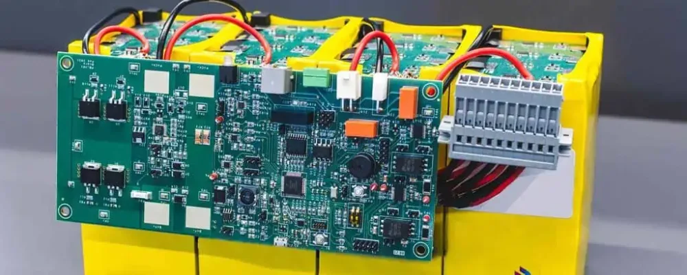
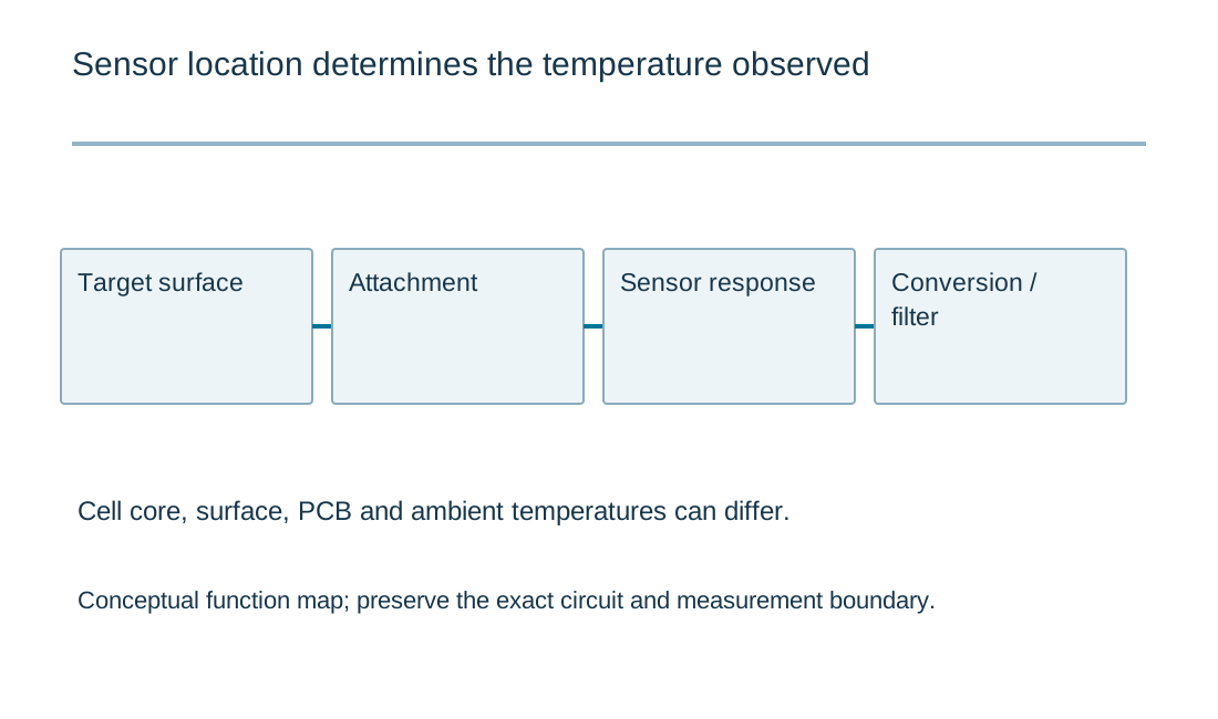
Map each sensor to the condition it is expected to observe: a cell surface, a connector, a balancing resistor area, a power switch region or ambient air. These locations can have different temperatures and different response times. A board temperature reading may help protect local electronics without representing the hottest cell or the cell core.
Write the intended decision beside the location. A channel used for trend logging may tolerate a different delay from one used in a defined protective response. The applicable cell and system requirements determine limits; a generic website must not provide one temperature window for every chemistry and product. Preserve the source and revision of each requirement.
Consider the representativeness of the location. One sensor on a large structure may miss gradients, and a sensor beside a heat-producing component may report the component's influence rather than the intended target. Layout, attachment, enclosure and airflow all affect the thermal path. Specify them before interpreting a nominal sensor accuracy as installed accuracy.
Choose the electrical interface and diagnostic behavior
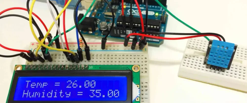
Thermistors offer a resistance that changes with temperature and need a defined excitation and conversion path. Integrated sensors may provide an analog or digital output with their own supply, conversion and timing requirements. The interface choice should account for cable length, reference, power state and how a disconnected or shorted sensor is identified.
For a divider, compare resistor tolerances, ADC reference behavior and input acquisition. If the supply used for excitation is related to the ADC reference, some supply variation may cancel in a ratio, but only within the actual circuit assumptions. A separate current-source excitation follows a different equation. Do not treat every temperature-input pin as a high-impedance ADC node.
Keep diagnostics distinct from ordinary range checks. A disconnected probe can drive an input toward a rail that software might otherwise interpret as an extreme temperature. The exact circuit determines the fault signature. Define an invalid state and the system's response instead of converting every electrical code into a plausible number of degrees.
| Review item | What to establish |
|---|---|
| Location | Physical target, sensor attachment and representative thermal path. |
| Interface | Excitation, conversion, supply/reference relationship and open/short diagnosis. |
| Timing | Physical lag plus acquisition, communication and action boundaries. |
| Assembly | Controlled geometry, adhesive or mounting and attachment inspection. |
| Evidence | Separate electrical, calibration, installed-response and system tests. |
First-order sensor response illustration
First-order sensor response illustration
Use the current inputs and keep the assumptions
Load the example to inspect its units, then clear it before entering your own revision. Example values are deliberately labeled assumptions. Complete every field; an empty numeric input is not zero. Record the operating condition behind a value rather than copying the first number found on a component summary. For a comparison, keep the measurement boundary and units consistent.
Calculate after checking the inputs. Any edit invalidates the old result and disables its report download until you calculate again. An edited example remains identified as an example. Results and reports are generated locally without uploading a circuit or populating Contact. Attach the downloaded text manually if it helps explain the question. You can request a review directly without completing the tool.
| Input | What to establish before using it |
|---|---|
| Review reference | Nonconfidential revision label. |
| Initial temperature · °C | Initial sensor and environment temperature in a hypothetical step test. |
| Final local temperature · °C | Known local step, not a cell-core temperature inferred from a surface reading. |
| Assumed time constant · s | Measured or assumed first-order time constant; real probes may require a multi-node model. |
| Time after step · s | Time since the ideal step. |
Understand sensor lag without overinterpreting a model
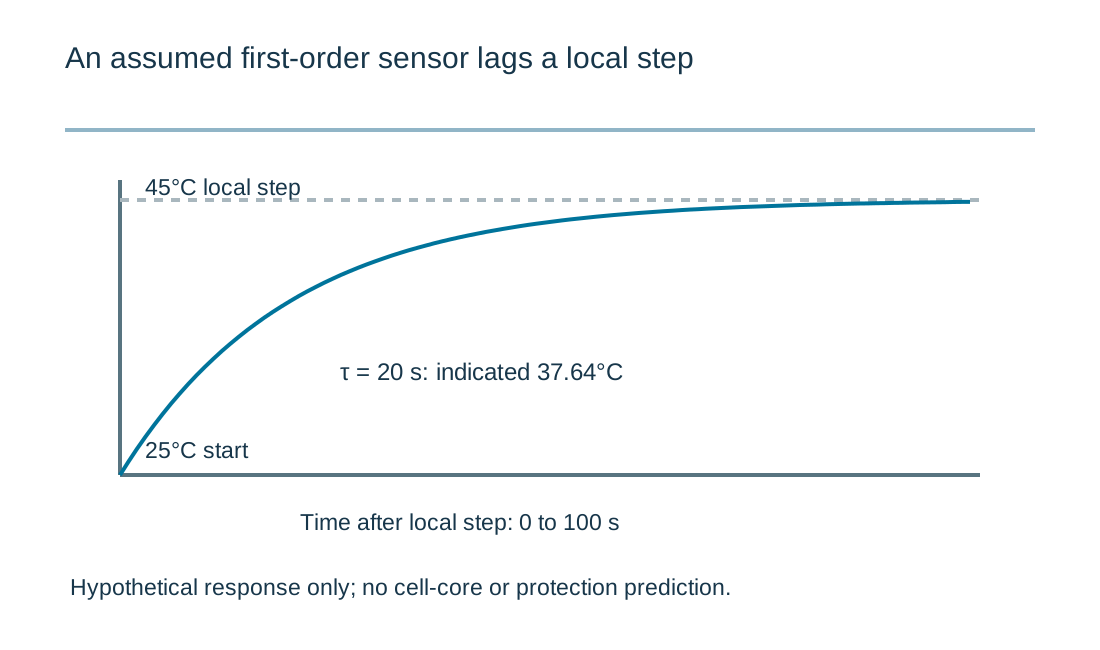
A first-order model illustrates a common response shape: the indicated temperature approaches a new local temperature exponentially after an ideal step. Its time constant describes how quickly that simplified response progresses. It does not describe every layer between a cell core, package surface, adhesive, sensor and measurement software.
For an example starting at 25°C with a local step to 45°C and a 20-second time constant, the model indicates about 37.64°C after 20 seconds. That is approximately 63.2% of the step. Reaching 90% takes about 46.05 seconds. These assumed values demonstrate lag; they are not measurements of a battery, probe or RAYPCB product.
The worksheet lets you examine this timing relationship while keeping the modeled boundary explicit. It cannot infer core temperature, forecast an abnormal thermal event or approve a protective response. Real installations may require several thermal nodes, varying heat generation and additional measurement delays. Use a measured response under relevant conditions to justify a model before relying on it in system analysis.
Add acquisition and control delays to the physical response
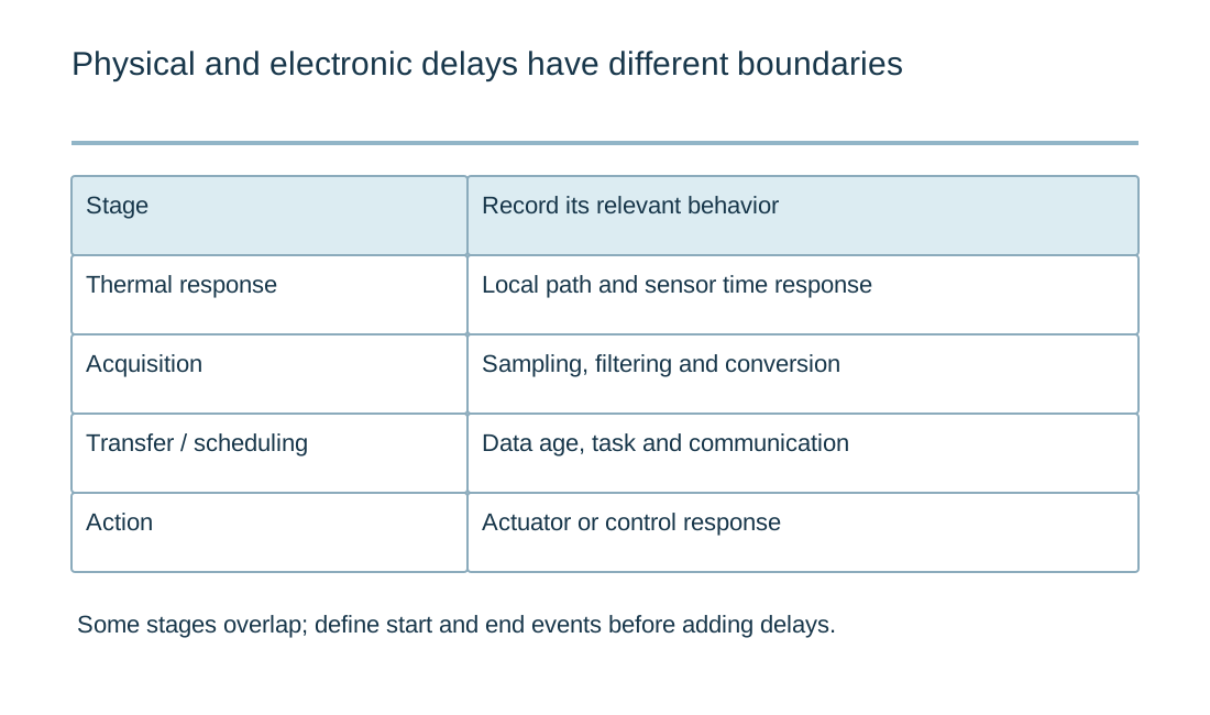
Physical sensor lag is only one part of an end-to-end response. Sampling interval, input filtering, conversion time, communication, task scheduling and actuator response may add delay. Some stages operate concurrently while others are sequential. Keep a timing diagram with the actual start and observation points rather than summing unrelated typical values.
Filtering can improve a noisy display while delaying a change. A moving average configured for visual smoothness may not suit another function that needs a bounded response. Record which value each function uses and whether diagnostics bypass or share the same filter. An out-of-date but well-filtered number is not necessarily a better measurement.
Define behavior when a sensor loses power or communication. If a controller retains the last reading, its timestamp and validity should remain available to the decision logic. A fresh message carrying an unchanged cached measurement is different from a fresh physical conversion. The digital thermometer circuit guide develops the measurement-chain and calibration aspects separately.
Design the thermal path as part of assembly
Specify sensor position, attachment method and the surfaces meant to exchange heat. Copper planes, leads and housing contact can conduct heat toward or away from the sensor. A layout change intended to improve soldering or mechanical support can therefore alter the reading or response time. Treat relevant geometry and materials as controlled features.
For remote probes, include strain relief, insulation, connector identity and inspection of attachment. A loose sensor may continue communicating correctly while no longer tracking the intended surface. Electrical continuity alone does not establish thermal coupling. If production verification includes the attachment or response, define a measurable method and acceptance criterion.
Avoid using an infrared image as a universal reference without accounting for surface properties and measurement conditions. Different surfaces and viewing arrangements can affect apparent temperature. A useful comparison records the reference method, location and uncertainty along with the sensor reading. The purpose is to establish the project's measurement boundary, not to select one instrument for every condition.
Build a verification record that supports the decision
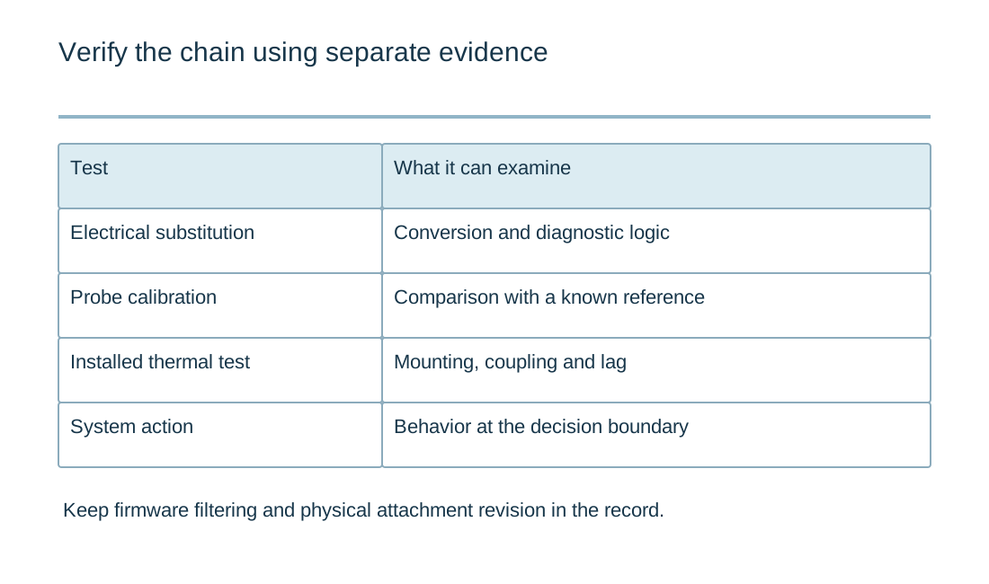
Separate electrical input tests, probe calibration, installed thermal response and system action. Each addresses a different part of the chain. A resistance substitution can verify conversion and logic without proving how quickly the installed probe follows the target. A temperature chamber test may not reproduce a local heat source or the final mounting arrangement.
Document the firmware filter, sampling configuration and diagnostic conditions with the physical revision. Review changes to adhesive, encapsulation, copper, cable or sensor package for their effect on the model. Keep failures and unexpected delays visible rather than reporting only a final equilibrium value. This produces more useful evidence for engineering review than a claim of high accuracy without a setup.
For a manufacturing inquiry, send the sensor map, circuit files, attachment drawings, quantity and the testing requested. Identify what remains a design task and what is already specified for production. The local response plot can explain a concern, but final acceptance must follow the actual product and its verified measurement chain.
Keep a measurement result separate from a protection decision
A battery measurement has a location, timestamp, operating state and uncertainty. A limit has an authoritative source and an assigned response. Connect those two records explicitly before implementing a protection function. A monitor reading that appears plausible is not proof that every cell connection, temperature input or current path is valid.
Keep the cell manufacturer's operating requirements with the system design. Identify which circuitry remains active when the host is unavailable and which recovery actions require independent conditions. Configuration and calibration must be versioned as carefully as the PCB. When requesting assembly, state whether the work stops at the populated board or includes programming, calibrated measurements and a defined system test. A worksheet supports this discussion; it cannot authorize pack operation or turn an unknown requirement into a default threshold.
Standards, source context and limits
Use the exact device revision and application conditions when applying manufacturer guidance. Reference designs are evidence about a specified implementation, not automatic validation of a modified board. Workmanship inspection, functional verification, product safety and application performance are different acceptance tasks. Public summaries do not replace the applicable licensed standards or a project-specific acceptance specification.
For fabrication scope and the agreed construction requirements, see PCB manufacturing.