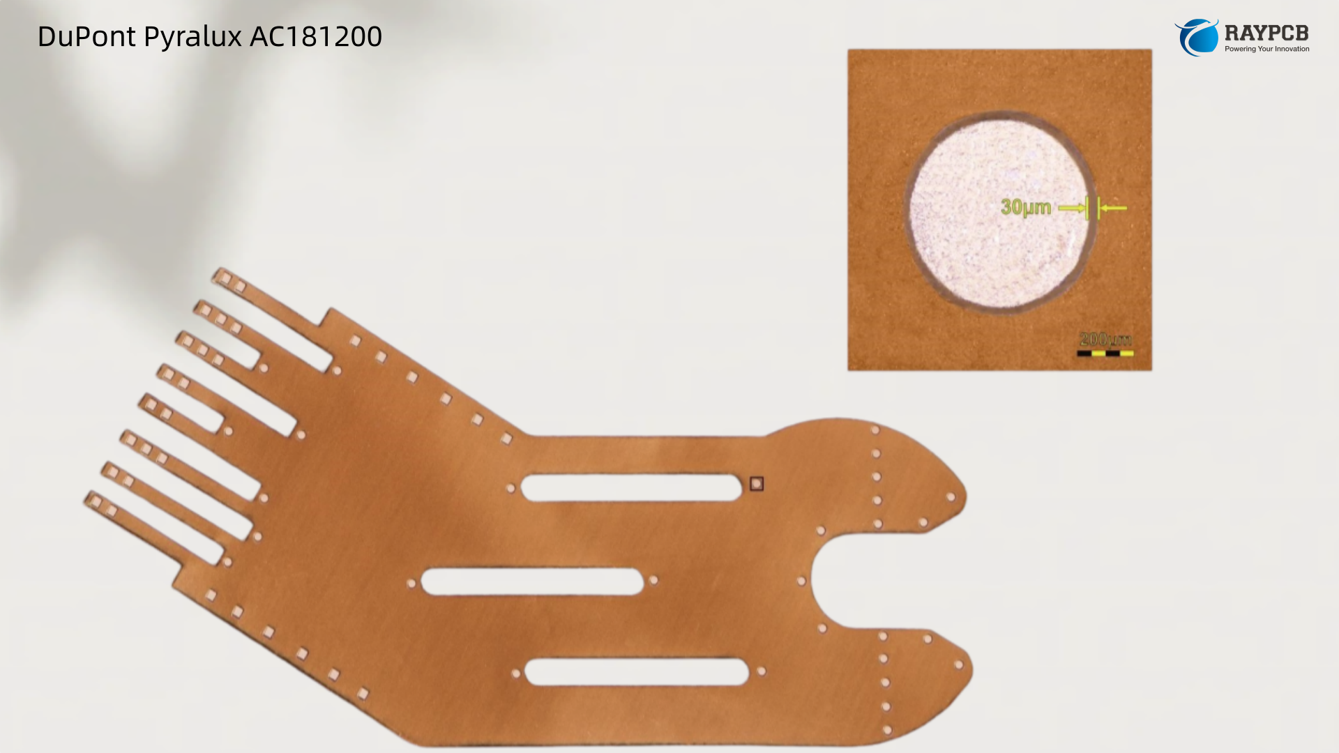
DuPont Pyralux AC181200 — a 1 oz RA copper / 1 mil adhesive / 2 mil Kapton single-sided flex laminate for military and aerospace use. This engineer guide covers specs, construction decode, IPC certification, processing notes, and comparisons to AP and LF series flex laminates.
If you’ve spent any time spec’ing flex materials for high-reliability platforms — avionics wiring harnesses, soldier-worn electronics, naval sonar arrays — you already know the name Pyralux. It’s the benchmark. Among the many constructions in the DuPont flexible laminate lineup, the DuPont Pyralux AC181200 represents one of the most widely deployed single-sided flex configurations in defence and mil-aero work: 1 oz rolled-annealed copper over a 1 mil acrylic adhesive layer bonded to a 2 mil Kapton polyimide film.
This guide breaks down what that construction actually means, where it performs, where it doesn’t, and what you need to know before you call it out in your next BOM.
What Is DuPont Pyralux AC181200?
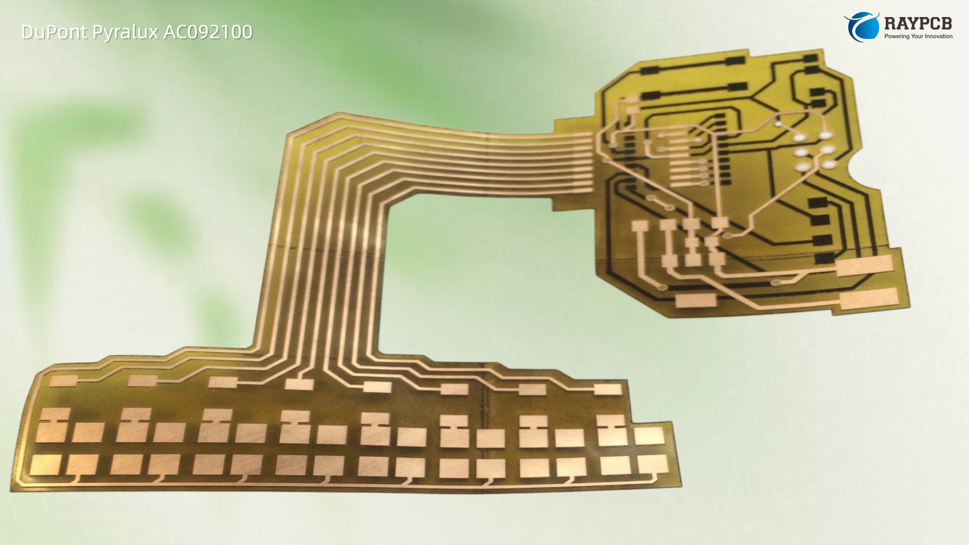
DuPont Pyralux AC is an all-polyimide single-sided copper-clad laminate ideal for applications that require thin, light, and high-density circuitry along with chip-on-flex attachment.
The AC181200 product code describes a specific single-sided flex construction within the Pyralux AC family. Decoding the product number helps you understand exactly what you’re ordering:
| Code Segment | Interpretation |
| AC | Pyralux AC family — all-polyimide single-sided clad |
| 18 | 18 µm copper thickness (nominally 1 oz/ft² RA copper) |
| 12 | 1 mil (25 µm) adhesive layer |
| 00 | 2 mil (50 µm) Kapton® polyimide base dielectric |
The resulting laminate stack from substrate up is: 2 mil Kapton® → 1 mil acrylic adhesive → 1 oz RA copper foil. Total dielectric build (adhesive + Kapton) is approximately 3 mils (76 µm), which puts it in a common sweet spot for single-layer military flex designs that need mechanical robustness without excessive thickness.
Pyralux AC is a single-sided copper-clad material offered in rolls that meets IPC-4204/25. The base polyimide is cast onto the copper, allowing thinner clads than traditional manufacturing processes would allow.
Key Specifications for DuPont Pyralux AC181200
| Property | Value |
| Construction Type | Single-sided copper-clad |
| Copper Thickness | 18 µm / 1 oz/ft² (RA) |
| Adhesive Thickness | 1 mil (25 µm) acrylic |
| Polyimide (Kapton) Thickness | 2 mil (50 µm) |
| Total Dielectric Build | ~3 mil (76 µm) |
| IPC Certification | IPC-4204/25 |
| Copper Type | Rolled Annealed (RA) |
| UL Flammability Rating | UL 94V-0 |
| Max Operating Temperature | Up to 150°C continuous (adhesive-limited) |
| Solder Float Resistance | 288°C per IPC-TM-650 2.4.13 |
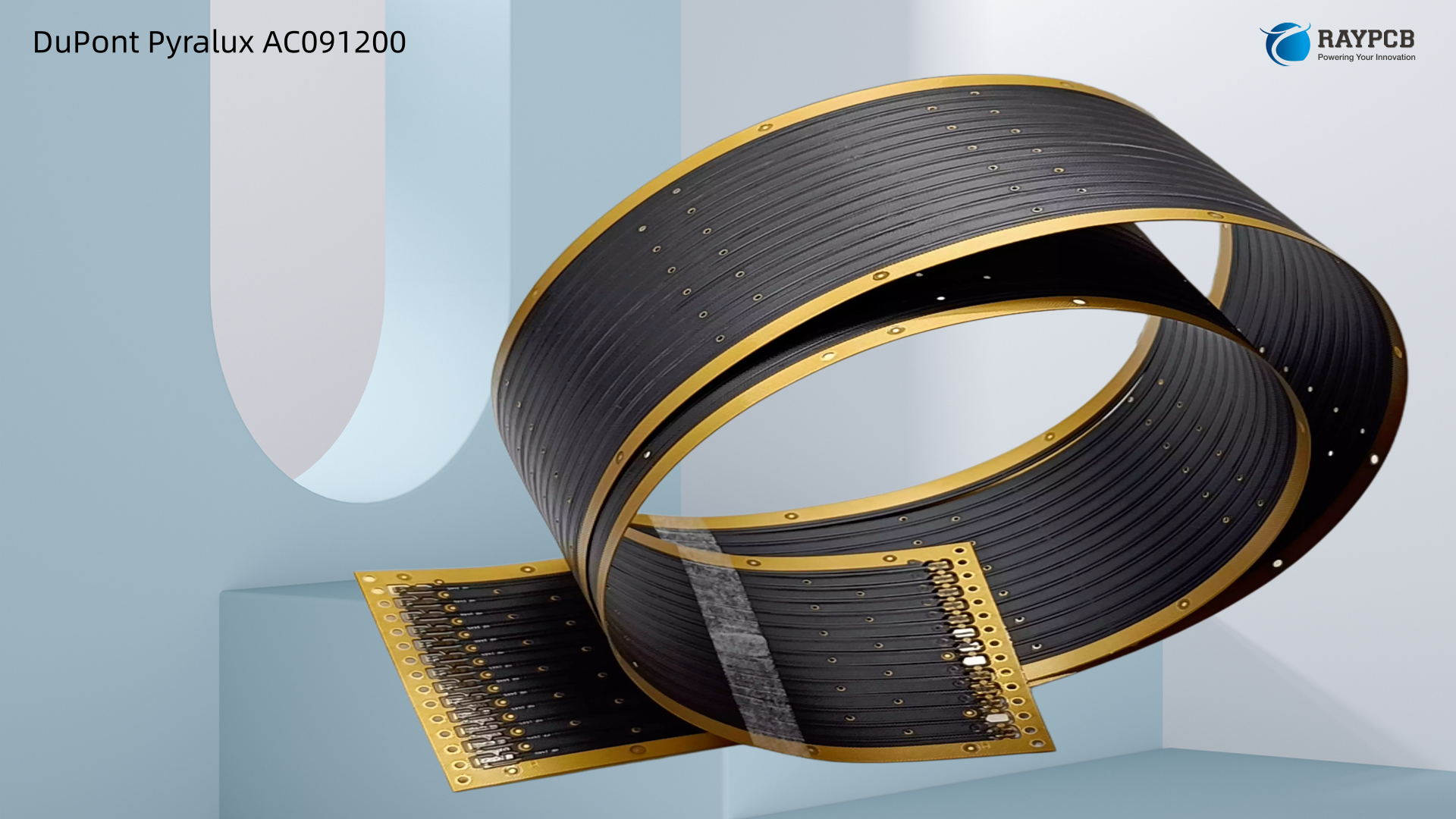
| Supply Format | Rolls |
DuPont Pyralux AC flexible laminates are warranted for two years from the date of manufacturing when stored in the original packaging at temperatures of 4–29°C (40–85°F) and below 70% relative humidity. The products do not require refrigeration and should not be frozen.
Understanding the Three-Layer Construction
Why Rolled-Annealed Copper Matters in Military Flex
The copper designation here is critical, and it’s something that often gets glossed over in procurement. Rolled-annealed (RA) copper is mechanically worked and annealed during manufacturing, which aligns the copper grain structure. For single-sided flex circuits that see repeated dynamic flexing — connector tails in avionics equipment, hinged display assemblies, wearable soldier systems — RA copper has substantially better flex endurance than electro-deposited (ED) copper, which has a more brittle, columnar grain structure.
In static flex designs (boards bent once during installation and never again), ED copper is typically fine and costs less. But for anything seeing cyclic or dynamic flex, calling out RA copper in your drawing notes isn’t optional — it’s how you avoid field failures.
The 1 Mil Acrylic Adhesive Layer
Adhesive-based laminates per IPC-4204/1 use acrylic adhesives that typically have glass transition temperatures around 70–100°C and begin degrading above 150°C.
This is the single biggest design constraint engineers need to plan around with the AC181200. The acrylic adhesive gives you excellent copper bond strength, good chemical resistance, and cost-effective processing, but it caps your continuous operating temperature. For most mil-aero avionics operating in conditioned bays or cockpit environments (where ambient rarely exceeds 85–100°C), this is a non-issue. For under-engine or near-exhaust applications, it’s a show-stopper — consider adhesiveless AP series instead.
Even if your end application is at room temperature, the flex circuit will experience 260–288°C during reflow soldering. Specify materials with adequate solder float resistance per IPC-TM-650 2.4.13. The AC181200 passes this test, but know your thermal budget before you assume this is suitable for high-temperature end use.
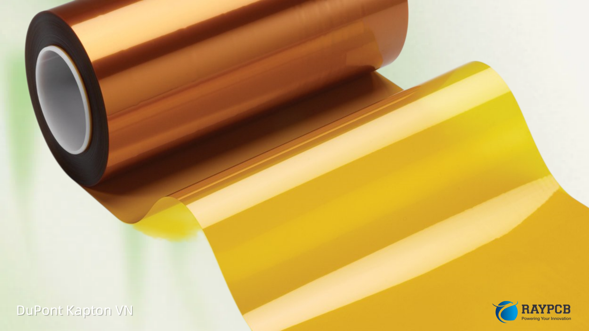
The 2 Mil Kapton Dielectric Base
The 2 mil Kapton polyimide film is the workhorse of the stack. Kapton is DuPont’s proprietary polyimide film and it has been the military flex dielectric baseline for decades — it appears in practically every high-reliability flex spec for a reason. It’s dimensionally stable, radiation resistant to levels relevant for most military electronics (not deep space), chemically inert to most solvents encountered in field environments, and it survives the full MIL-STD thermal cycling range easily.
Pyralux AC materials show excellent dimensional stability, low moisture absorption, high modulus, excellent thermal resistance, and excellent long-term thermal aging.
The 2 mil thickness hits a balance point. At 1 mil, you get more flexibility but the circuit becomes difficult to handle in fabrication and prone to wrinkling. At 3–5 mil, you’re adding Z-height and stiffness that reduces dynamic flex performance. Two mils is the go-to for single-layer military flex work where you need reliable imaging of fine traces but still want real-world handling behaviour on the fab floor.
Military and Defence Applications
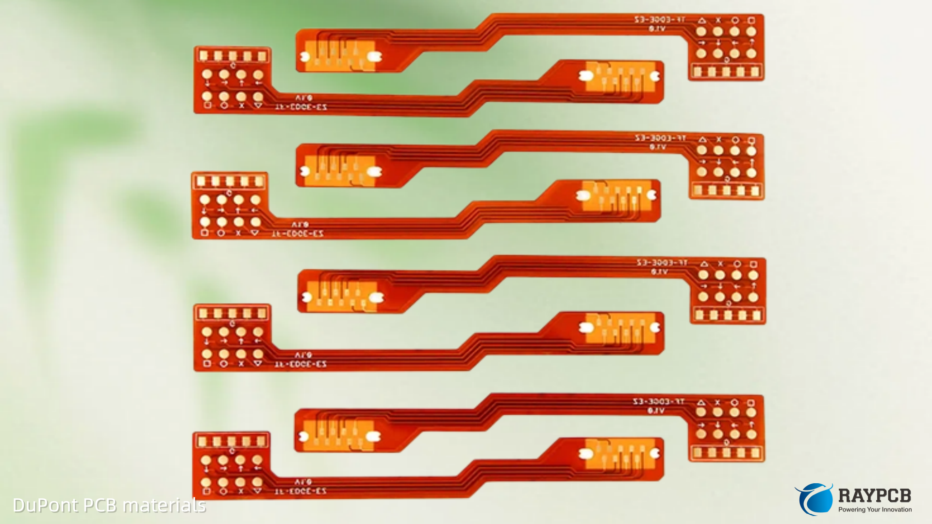
The DuPont Pyralux AC181200 sees regular use across several defence segments:
Avionics flex interconnects — Single-sided circuits connecting sensors, displays, and nav modules inside cockpit assemblies. The 2 mil Kapton provides the dimensional stability needed to maintain connector registration across wide temperature swings from ground cold soak to operating altitude.
Soldier-worn electronics — Body-area flex circuits for communications, GPS, and biometric monitoring equipment. Here the 1 oz RA copper combined with the 2 mil Kapton dielectric gives the flex-fatigue performance needed for equipment that bends every time the wearer moves.
Naval electronics — Humidity and moisture resistance of Kapton-based flex makes it appropriate for shipboard electronics where condensation is a real-world concern. The material demonstrates thermal and humidity resistance and is characterised by low moisture absorption.
Missiles and munitions electronics — Space-constrained single-sided circuits for fuzing and guidance electronics often use single-layer Kapton flex. The material’s ability to survive the vibration and shock profiles of launch and flight makes it a viable option here.
Radar and antenna feedlines — Though not a low-loss RF specialist material, the AC181200 appears in low-frequency radar interconnect and antenna switching flex assemblies where its dimensional stability and known Dk behaviour are more important than insertion loss.
Comparing AC181200 to Related Pyralux Constructions
One of the most common questions from engineers new to flex materials is: when do I use AC vs. AP vs. LF vs. FR? Here’s a practical comparison at the flex laminate level:
| Property | AC181200 | AP8525R (Adhesiveless) | LF Series (Acrylic) | FR Series (Flame Retardant) |
| Cu Thickness | 1 oz RA | Varies (0.5 oz std) | Varies | Varies |
| Adhesive | 1 mil acrylic | None (adhesiveless) | Acrylic | Acrylic (FR) |
| Dielectric | 2 mil Kapton | 2 mil PI | Kapton | Kapton |
| IPC Cert | IPC-4204/25 | IPC-4204/11 | IPC-4204A/1 | IPC-4204A/1 |
| Max Temp (Cont.) | ~150°C | 180°C | ~150°C | ~150°C |
| UL Flame Rating | V-0 | V-0 | V-0 | V-0 (FR enhanced) |
| Sided | Single | Double | Single/Double | Single/Double |
| Typical Use | Mil flex, COF | Rigid-flex, HDI | General flex | UL-rated flex |
IPC-4204/1 specifies polyimide laminate with acrylic adhesive (3-layer construction), while IPC-4204/11 specifies adhesiveless polyimide (2-layer construction). The adhesiveless construction of IPC-4204/11 provides better dimensional stability, higher temperature capability, and thinner profiles, making it preferred for HDI, rigid-flex, and high-reliability applications. However, IPC-4204/1 materials are typically 20–30% lower cost and perfectly suitable for many static flex applications.
Processing and Fabrication Notes
The AC181200 is designed for roll processing and high-volume fabrication. A few things that matter in practice:
Etchant compatibility — The RA copper etches well with standard cupric chloride and ferric chloride chemistries. The acrylic adhesive layer is inert to these etchants but can be sensitive to aggressive alkaline cleaners. Brief the fab shop on any process steps that involve strong alkalis.
Lamination — When building multilayer assemblies, please specify DuPont Pyralux AC Plus flexible circuit material for use with pre-pregs. Pyralux AC Plus is specifically treated for additional bond strength. For standard single-layer work, the AC181200 processes with conventional flex fab tooling.
Drilling and routing — Pyralux AC should be handled carefully; anyone handling it should wash hands before eating, smoking, or using restroom facilities. Gloves, finger cots, and finger pads should be changed daily. At 2 mil Kapton, mechanical drilling requires sharp tooling and controlled feed rates to avoid delamination.
Solder mask and coverlay — DuPont’s Pyralux FR coverlay is the standard companion material for AC181200 circuits needing environmental protection. The acrylic adhesive in the coverlay is chemically compatible with the laminate adhesive system.
Engineers building for DuPont PCB applications should verify their fabricator’s experience with Kapton-based flex before qualifying a new vendor — the process window is narrower than FR4 and inexperienced shops introduce registration and yield problems.
Useful Resources for Engineers
- DuPont Pyralux AC Official Product Page: dupont.com
- Official Pyralux AC Datasheet (PDF): qnityelectronics.com — EI-10122
- IPC-4204 Standard Overview (Flex Laminates): IPC.org
- IPC-TM-650 Test Methods: IPC.org/TM-650
- Insulectro Pyralux AC Product Page: insulectro.com/products/pyralux-ac
- Adafruit Pyralux AC Datasheet Reference: cdn-shop.adafruit.com
- RayPCB DuPont PCB Manufacturing: raypcb.com/dupont-pcb
- DuPont Pyralux Safe Handling Guide: pyralux.dupont.com
FAQs: DuPont Pyralux AC181200
Q1: What does the “all-polyimide” designation mean for the AC181200 if it includes an acrylic adhesive? The “all-polyimide” description in the Pyralux AC line refers to the base dielectric film being Kapton polyimide rather than a different substrate. The construction still includes an acrylic adhesive layer bonding that polyimide to the copper. This is distinct from the truly adhesiveless AP series where copper is bonded directly to polyimide through casting or sputtering with no intermediate adhesive.
Q2: Is the AC181200 suitable for flex circuits that see dynamic repeated bending? Yes, with important caveats. The 1 oz rolled-annealed copper has significantly better flex endurance than electro-deposited copper at the same weight. However, 1 oz is relatively thick for tight-radius dynamic flex applications. If your bend radius is below approximately 10x the total circuit thickness, consider dropping to 0.5 oz RA copper instead.
Q3: Can AC181200 be used in MIL-SPEC designs requiring IPC-4204 certification? Pyralux AC meets IPC-4204/25. Confirm the specific slash sheet required by your program specification, as military contracts may call out a particular IPC-4204 variant. IPC-4204/25 is the relevant slash sheet for this single-sided all-polyimide single-sided clad construction.
Q4: What is the shelf life and storage requirement for AC181200? Pyralux AC flexible laminates are warranted for two years from the date of manufacturing when stored in the original packaging at temperatures of 4–29°C (40–85°F) and below 70% relative humidity. The products do not require refrigeration and should not be frozen. The material should be kept clean and well protected from physical damage.
Q5: How does the AC181200 compare to the Pyralux LF series for military applications? Both the AC and LF series use acrylic adhesive and Kapton film, but they differ in construction format (AC is single-sided roll-format; LF is available in both single and double-sided sheet formats) and their specific IPC certifications. Pyralux LF has been the industry standard in high-reliability applications for over 35 years with a proven record of consistency and dependability. For programmes where LF is an established approved material, switching to AC requires requalification even if the raw performance is comparable. Talk to your DPM or cognizant engineer before substituting.
The Bottom Line on DuPont Pyralux AC181200
The DuPont Pyralux AC181200 is not a glamour material. It’s not the thinnest flex laminate on the market, it doesn’t have the temperature ceiling of the adhesiveless AP series, and it won’t win a dielectric constant competition with PTFE-based laminates. What it is, is a mature, well-characterised, IPC-qualified construction that has been flying in military systems and ground vehicles for decades. The combination of 1 oz RA copper, 1 mil acrylic adhesive, and 2 mil Kapton is one of the most battle-tested flex laminate stacks in existence. For programmes where schedule, material traceability, and supply chain confidence matter more than squeezing out the last half-mil of thickness, this is still a very rational choice.
Know your operating temperature ceiling, size your bend radii appropriately for 1 oz copper, and qualify your fabricator on Kapton processing before committing to a production build.
Suggested Meta Description
DuPont Pyralux AC181200 — a 1 oz RA copper / 1 mil adhesive / 2 mil Kapton single-sided flex laminate for military and aerospace use. This engineer guide covers specs, construction decode, IPC certification, processing notes, and comparisons to AP and LF series flex laminates.
(156 characters — within Yoast SEO’s recommended 150–160 range, with the target keyword “DuPont Pyralux AC181200” placed within the first 30 characters.)