
RAYPCB · ENGINEERING GUIDE
Pyralux AC091200: Thin Copper and Single-Sided Flex
Pyralux AC091200 identifies a thin, single-sided adhesiveless flex construction: the current manufacturer table lists AC091200EN with 9 µm ED copper and 12 µm dielectric. The suffix matters. This page addresses fine conductor resistance and handling, while the full foil treatment and present supply remain quotation items.
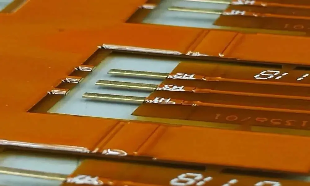
Establish the conductor after processing
Thin starting foil can support a fine-line process, but starting thickness is not a guaranteed finished feature. Ask for the minimum finished width and copper thickness at the critical trace, including any plating route. A uniform rectangular approximation is useful for resistance; it cannot set the fabricator's minimum line and space or predict etch profile.
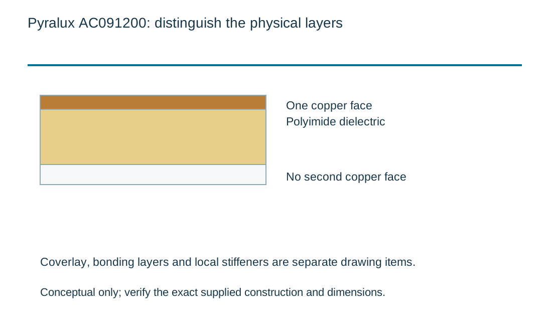
Construction and decision boundaries
| Review item | What this page establishes | What remains project-specific |
|---|---|---|
| Current listed example | AC091200EN | Full suffix identifies the foil variant. |
| Construction | Single-sided copper and all-PI dielectric | No second foil assumed. |
| Conductor task | Finished cross-section resistance | No minimum-feature guarantee. |
Quantify the electrical tradeoff
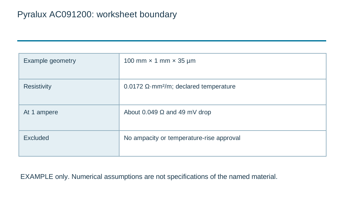
For an assumed 100 mm trace, 0.2 mm width, 9 µm copper and resistivity 0.0172 Ω·mm²/m, resistance is about 0.956 Ω. At 0.1 A that represents approximately 0.096 V drop. The same geometry with twice the conductor thickness halves the ideal resistance. Contacts, neck-down regions and temperature add further considerations, so use this as a screen before a complete circuit review.
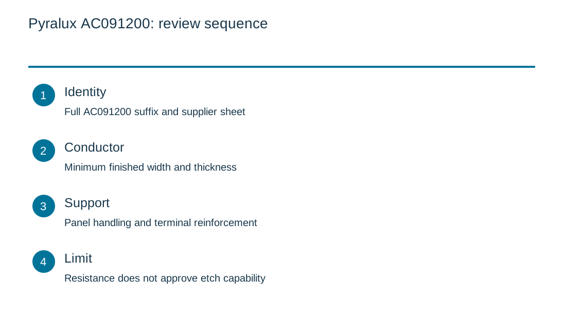
| Review item | What to establish |
|---|---|
| Identity | Full AC091200 suffix and supplier sheet |
| Conductor | Minimum finished width and thickness |
| Support | Panel handling and terminal reinforcement |
| Limit | Resistance does not approve etch capability |
Copper trace resistance and voltage drop
Copper trace resistance and voltage drop
Use the current inputs and keep the assumptions
Start with the example only to inspect the units and the calculation boundary. Replace every assumption with a value tied to your own document or measurement. An empty numeric field is not zero. The review-reference field is a local label; avoid entering customer names, confidential part numbers or other private information into a public worksheet.
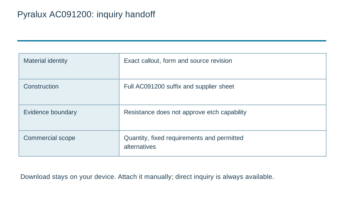
After calculating, read the notes alongside the numerical result. Changing any input invalidates the displayed result and disables its download until you calculate again. For a comparison, keep the units, geometry, material condition and measurement boundary consistent. A long decimal result does not imply equally precise input data. The downloadable record stays on your device and can be attached manually to an inquiry. It is not automatically transferred into the Contact form.
If an input is unknown, identify the person or document needed to resolve it. Do not fill a gap with a favorable generic value simply to obtain a result. You can request a material or fabrication review without using the tool. The arithmetic illustrates a relationship; it does not accept a construction, certify a material, establish current pricing or replace a supplier process specification.
| Input | What to establish before using it |
|---|---|
| Review reference | Nonconfidential revision label. |
| Trace length · mm | Uniform straight conductor equivalent. |
| Finished trace width · mm | Minimum finished width for this scenario. |
| Finished copper thickness · µm | Measured or specified finished copper. |
| Current · A | DC current; no ampacity or temperature-rise approval. |
| Copper resistivity · Ω·mm²/m | Assumed value at a declared temperature; adjust from verified data. |
Optional cost comparison from your own allowances
Use a quotation or a clearly labeled internal assumption for each input. Keep the quantity, construction and inspection scope the same when comparing alternatives. This uncalibrated planning model adds entered values; it contains no current market rates and does not issue a RAYPCB quotation. You can contact the team without completing it.
Optional project allowance comparison
Plan how the thin circuit is supported
Identify the panel carriers, temporary support and connector reinforcement needed by the manufacturing and assembly route. Avoid treating a free film sample as representative of the loaded assembly. The handling requirement may be driven by small termination features rather than the broad flexible span. Clarify which supports remain in the product and which are removed.
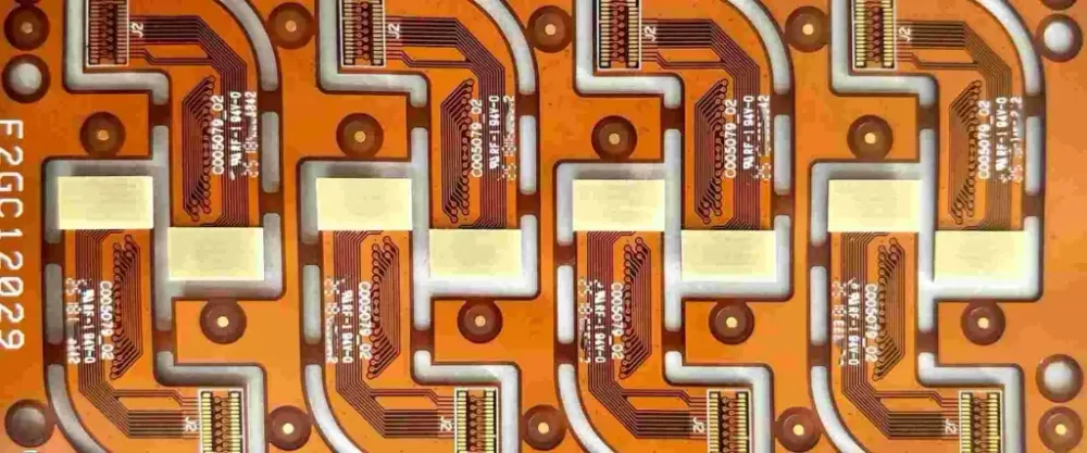
Compare sidedness as well as thickness
AC181200 keeps a thin base while changing the copper class. AC182500 changes the dielectric section. A double-sided grade such as AP7163E is a different circuit architecture, even if a foil gauge looks similar. Adding a reference plane changes both return-current behavior and mechanical response.
Preserve the exposed-contact geometry
Show contact length, pitch, coverlay boundary and local stiffener position. Small registration errors can consume a substantial fraction of the useful contact area. The contact finish, connector requirement and insertion process should be reviewed together. Do not add a universal stiffener thickness without the mating connector drawing.
Request the feature that matters
Send the critical trace widths, acceptable voltage drop, connector details and support requirements. Ask for the full offered AC code rather than ordering the shortened URL label. Compare quotations with the same final copper and inspection requirements; a material-only price cannot capture fine-feature yield or assembly support.
Measure the fine conductor where the connector constrains it
| Review point | Input to record | Decision or verification |
|---|---|---|
| Critical feature | Mark the narrowest neck after patterning rather than only the CAD line width. | Use that finished cross-section in the resistance calculation. |
| Electrical check | Separate the trace segment from connector and probe contact resistance. | Compare measured and calculated values at a documented temperature before diagnosing an etching issue. |
| Handling | Identify the support that carries the thin single-sided part into assembly. | Inspect local distortion at exposed contacts after support removal. |
Use the review points above alongside the worked example on this page. Record the chosen inputs with the drawing revision and send unresolved items with the enquiry. A supplier response should identify the proposed construction and the evidence needed for release.
Standards, source context and limits
Use the edition, amendment and material-document revision named in the purchase agreement. A standards title, marketing label or supplier product family does not establish that a particular lot meets a requirement. Public summaries are useful for scope; the controlled specification and applicable test method govern acceptance.
The examples on this page are illustrative engineering scenarios. They are not RAYPCB production records or guaranteed material values. Source links identify the organizations responsible for the referenced information. Confirm applicability to the exact grade, construction and test condition before carrying a number into a drawing or qualification report. For a flex board, distinguish the design requirements in IPC-2223, finished-board qualification and performance in IPC-6013, and the material scopes of IPC-4202, IPC-4203 and IPC-4204. These cover different deliverables; naming them does not certify the material or factory. State the contracted revision and applicable material sheet. Source review date: 3 October 2026. Legacy designation, present availability and an approved replacement are separate questions.
For fabrication scope and the agreed construction requirements, see PCB manufacturing.

