Learn how to read a Bergquist thermal clad datasheet like an engineer — thermal resistance calculations, HPL-03015 vs HT-04503 comparison tables, IMS PCB layout rules, and FAQs for LED and power electronics designers.
If you’ve ever opened a Bergquist thermal clad datasheet and wondered which numbers actually matter for your LED or power electronics design, you’re not alone. The datasheets pack in a lot of electrical, thermal, and mechanical specs—and not all of them carry equal weight depending on your application. This guide walks through each section from a working PCB engineer’s perspective, covers how to use those numbers in real thermal resistance calculations, compares the two most commonly specified dielectrics (HPL-03015 vs HT-04503), and spells out the layout rules you need to actually build a reliable IMS board.
What Is Bergquist Thermal Clad (and Why Does It Matter)?
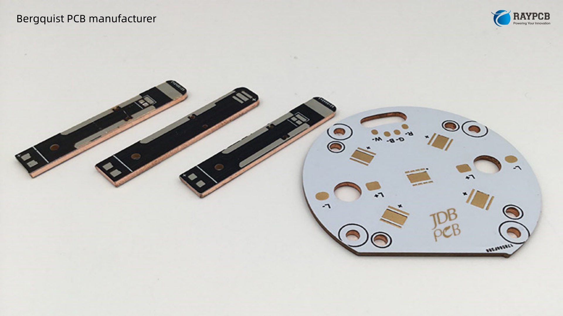
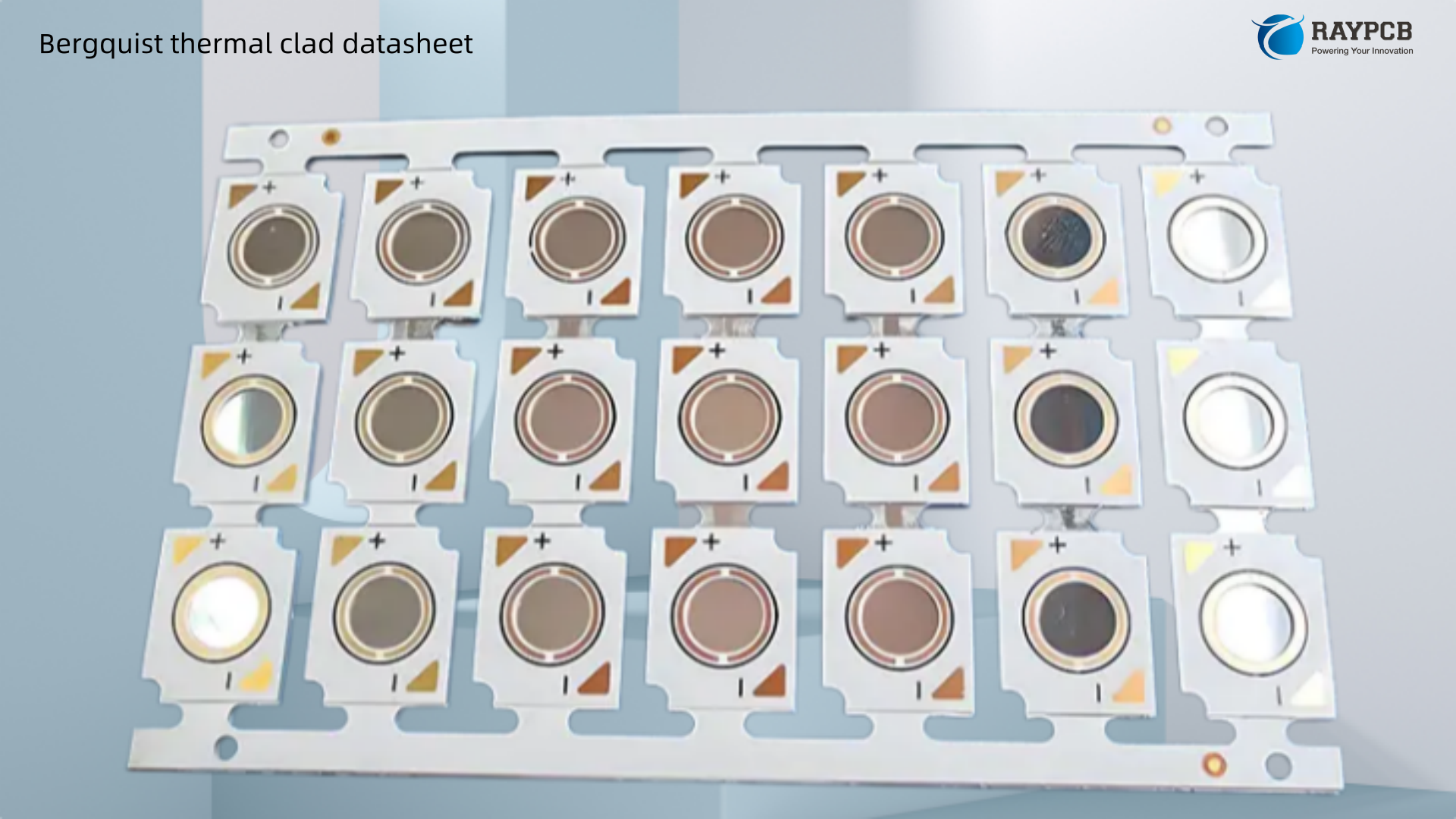
Bergquist Thermal Clad is a family of Insulated Metal Substrate (IMS) PCBs developed specifically for high-watt-density surface-mount applications. The stackup is simple—copper circuit layer on top, a proprietary polymer-ceramic dielectric in the middle, and an aluminum (or copper) base beneath—but the technology in that dielectric layer is what separates it from generic aluminum-core boards.
Thermal Clad MCPCBs minimize thermal impedance and conduct heat more effectively than standard printed wiring boards, and they are more mechanically robust than thick-film ceramic and direct bond copper construction. For LED lighting and power conversion applications, this translates directly to lower junction temperatures, longer component lifetimes, and the ability to run more forward current per LED without cooking the package.
The low thermal impedance of the Thermal Clad dielectric out-performs other insulators for power components, allowing for cooler operation. Thermal Clad keeps assemblies cool by eliminating thermal interfaces and using thermally efficient solder joints.
Now that’s the marketing pitch. Let’s talk about how to actually use the datasheet.
The Structure of a Bergquist Thermal Clad Datasheet
Every Bergquist Thermal Clad datasheet (now published under Henkel, which acquired Bergquist) follows the same basic architecture. Understanding what each section means before you start comparing part numbers will save you hours of back-and-forth with your fab house.
Dielectric Identification and Product Series
The part number itself encodes critical information. Take HPL-03015 as an example:
- HPL = High Power Lighting dielectric family
- 030 = Thermal resistance in °C·in²/W × 100 (so 0.30 °C·in²/W)
- 15 = Dielectric thickness in tenths of mils (so 1.5 mils / 38 µm)
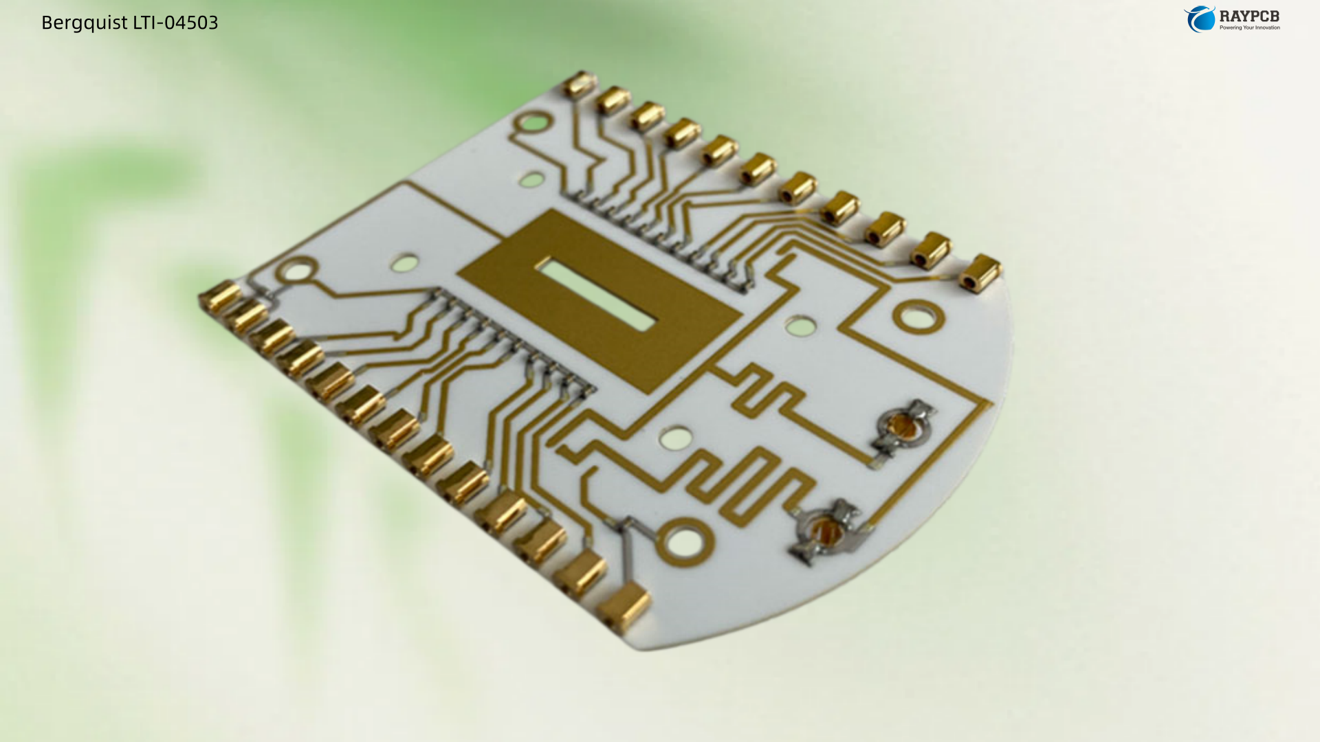
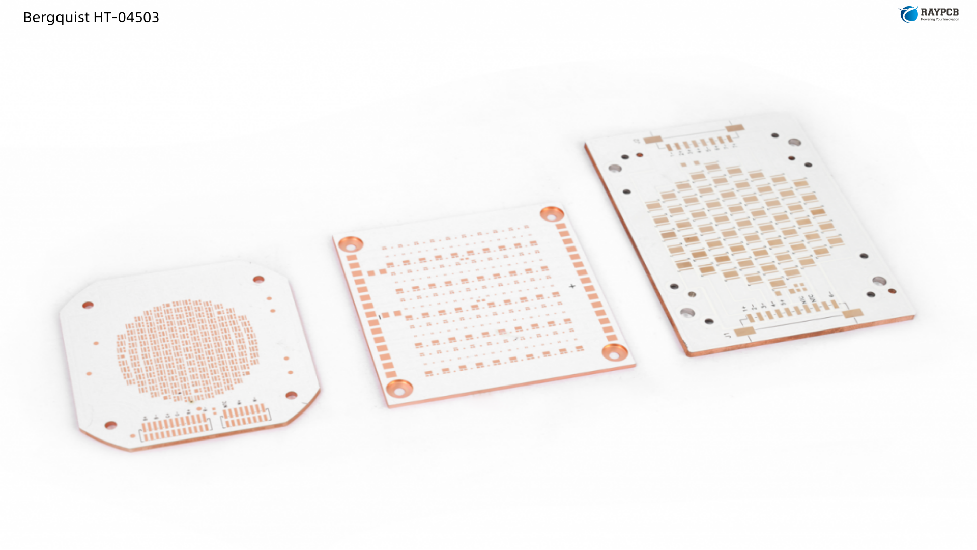
The same logic applies to HT-04503: HT (High Temperature), 045 = 0.45 °C·in²/W, 03 = 3 mils / 76 µm thick. Once you internalize this convention, you can decode any Thermal Clad part number at a glance.
Thermal Performance Parameters — The Numbers That Drive Your Design
This is the section most engineers should spend the most time on. There are three closely related values that often get confused:
Thermal Conductivity (W/m·K) — A material property, independent of thickness. Higher is better. Think of this as how efficiently the dielectric moves heat per unit of thickness.
Thermal Resistance (°C·in²/W or °C·W⁻¹) — This is thickness-dependent and tells you the temperature rise per watt per unit area. This is what you’ll plug into your junction-to-ambient thermal chain calculation.
Thermal Impedance (°C/W) — For a given test area (typically 1 in²), this is the total resistance of the complete laminate stack under test conditions.
For the HPL-03015, the dielectric thickness is 1.5 mil / 38 µm, thermal resistance is 0.30°C/W, and the unit thermal resistance is 0.02°C·in²/W. For HT-04503, thickness is 3 mil / 76 µm, thermal resistance is 0.45°C/W, and unit thermal resistance is 0.05°C·in²/W.
Dielectric Strength (kV)
This tells you the voltage the dielectric can withstand before breakdown. For LED luminaire designs running on mains voltage (120–240V AC), you need meaningful headroom above your working voltage. HT-04503 carries a breakdown voltage of 6.0 kV for LED applications. This is important not just for safety isolation, but for your creepage and clearance calculations in CE/UL-listed luminaire designs.
Operating Temperature and Glass Transition (Tg)
Tg is the temperature at which the dielectric shifts from a rigid, glassy state to a softer, rubbery state. Exceeding Tg repeatedly accelerates delamination and CTE-induced solder joint fatigue. The HPL-03015 dielectric at 0.0015″ (38µm) has a glass transition of 185°C. That’s an unusually high Tg for this class of material and is one of the reasons HPL-03015 is preferred for high-junction-temperature LED packages.
Copper Weight / Circuit Layer
Copper foil is NOT measured for thickness as a control method—instead it is certified to an area weight requirement per IPC-4562. The nominal thickness for 1 oz copper is 0.0014″ / 35 µm. Most LED IMS designs use 1 oz copper. If you’re running high current traces (motor drivers, DC-DC converters), consider 2 oz or 3 oz—but check your fab’s DFM rules first, as heavy copper requires modified etching chemistry.
UL RTI (Relative Thermal Index)
The RTI values (Electrical / Mechanical) define the long-term maximum operating temperature the material can sustain while retaining at least 50% of its original electrical or mechanical properties. HT-04503 carries UL RTI values of 140/140°C. This matters for lifetime assessments and product qualification under UL 746B.
Bergquist Dielectric Comparison Table
Here’s a side-by-side of the most commonly specified Thermal Clad dielectrics from the selection guide:
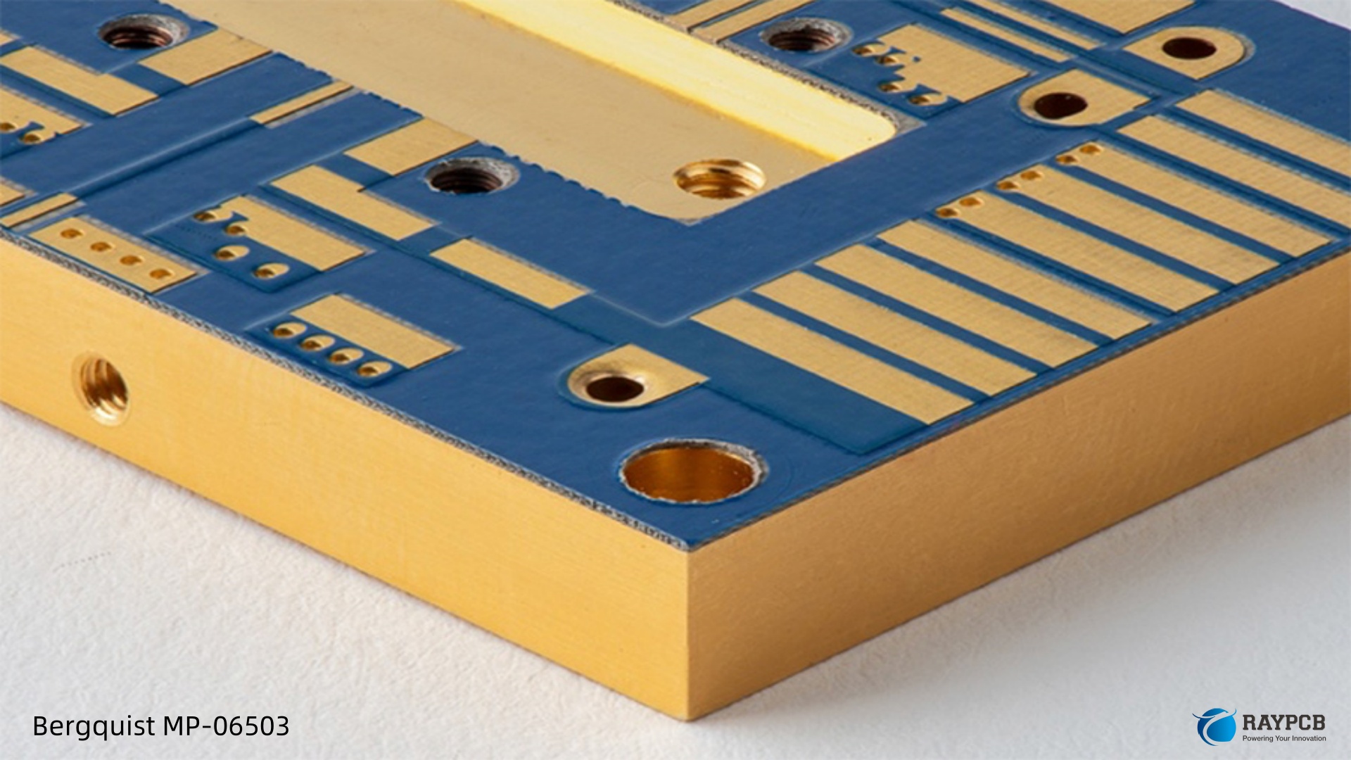
| Parameter | HPL-03015 | HT-04503 | HT-07006 | MP-06503 |
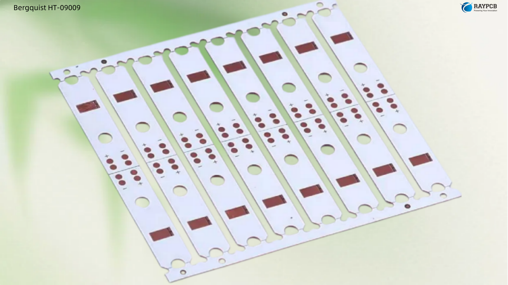
| Dielectric Thickness | 1.5 mil / 38 µm | 3 mil / 76 µm | 6 mil / 152 µm | 3 mil / 76 µm |
| Thermal Conductivity | 7.5 W/m·K | 2.2 W/m·K | 2.2 W/m·K | 1.3 W/m·K |
| Thermal Resistance (°C/W) | 0.30 | 0.45 | 0.70 | 0.65 |
| Unit Thermal Resistance (°C·in²/W) | 0.02 | 0.05 | 0.11 | 0.09 |
| Dielectric Strength (kV) | 2.5 | 6.0 | 11.0 | 8.5 |
| Max Operating Temp (°C) | 185 (Tg) | 150 | 150 | 90 |
| UL RTI Elec/Mech (°C) | — | 140/140 | 140/140 | 130/140 |
| Primary Application | High-power LED | LED, power, automotive | High-voltage, industrial | General purpose |
Source: Bergquist Thermal Clad Selection Guide (Henkel/Bergquist)
HPL-03015 vs HT-04503: Which One Should You Pick?
This is the question that comes up in almost every high-power LED design review. Here’s how to think through it practically:
Choose HPL-03015 When:
HPL is a dielectric specifically formulated for high power lighting LED applications with demanding thermal performance requirements. This thin dielectric at 0.0015″ (38 µm) has an ability to withstand high temperatures with a glass transition of 185°C and phenomenal thermal performance of 0.30°C/W. It is optimized for COB (Chip-on-Board) and high-lumen-density arrays where getting heat out fast is the primary constraint, and operating voltages are relatively low (under 60V DC in most SSL designs). With a unit thermal resistance of only 0.02°C·in²/W and thermal conductivity of 7.5 W/m·K, it’s the best-performing dielectric in the Thermal Clad lineup.
The trade-off: its dielectric strength is only 2.5 kV. That’s fine for low-voltage LED drivers, but not suitable for mains-isolated designs without additional creepage management.
Choose HT-04503 When:
HT-04503 is specifically designed for applications that involve high-power systems with significant heat dissipation requirements. Its ability to perform in high-temperature conditions makes it a popular choice for industries like automotive, telecommunications, and high-frequency circuits. The 6 kV breakdown rating gives you much better margin for line-voltage isolation, and the 2.2 W/m·K conductivity is still a significant improvement over FR-4.
If you’re designing an LED driver board with mains-referenced components mounted on the same substrate, or an automotive LED headlamp controller where 48V bus voltages are common, HT-04503 is the safer choice.
Decision Summary
| Design Condition | Recommended Dielectric |
| High-power LED array, low-voltage driver (< 60V) | HPL-03015 |
| Mains-isolated LED luminaire (120–240V) | HT-04503 |
| Automotive LED (12V/48V) with junction temp concern | HPL-03015 |
| Automotive power module with isolation requirement | HT-04503 |
| Industrial inverter / motor drive | HT-07006 |
| Cost-sensitive general purpose | MP-06503 |
Thermal Resistance Calculations for IMS PCB Design
Reading the datasheet is one thing. Actually using those numbers in a design calculation is where engineers often stumble. Here’s a practical walkthrough.
The Thermal Resistance Chain
For an LED mounted on an IMS board attached to a heatsink, the thermal resistance from junction to ambient looks like this:
Rθ(j-a) = Rθ(j-c) + Rθ(c-board) + Rθ(dielectric) + Rθ(base-metal) + Rθ(TIM) + Rθ(heatsink)
In practice, the base metal (aluminum) resistance is negligible — aluminum at 1.5mm thick contributes roughly 0.006°C/W per cm². The dominant resistance in an IMS stack is usually the dielectric layer, followed by the TIM between the IMS base and heatsink.
Calculating Dielectric Thermal Resistance
The formula is straightforward:
R_dielectric = (Unit Thermal Resistance) / (Component Footprint Area)
For a 3W LED with a 5mm × 5mm (0.025 in²) thermal pad on HPL-03015:
R_dielectric = 0.02 °C·in²/W ÷ 0.025 in² = 0.8 °C/W
The same LED on HT-04503:
R_dielectric = 0.05 °C·in²/W ÷ 0.025 in² = 2.0 °C/W
At 3W dissipation, that’s a 1.8W × (2.0 − 0.8) = 2.16°C difference in junction temperature from dielectric selection alone. Across a string of 20 LEDs running warm, that gap compounds quickly.
Example: Full Thermal Budget for an LED Street Light Module
| Thermal Node | Resistance | Notes |
| Junction to case (Rθjc) | 3.5 °C/W | From LED datasheet |
| Case to board (solder joint) | 0.5 °C/W | Estimated, low for SMT |
| IMS dielectric (HPL-03015, 25mm² pad) | 0.8 °C/W | Calculated above |
| Al base (1.5mm, 25mm²) | ~0.01 °C/W | Negligible |
| TIM (0.1mm, k=3 W/mK, 25mm²) | 0.6 °C/W | Depends on TIM choice |
| Heatsink to ambient | 2.5 °C/W | Natural convection, 60cm² |
| Total Rθ(j-a) | ~7.9 °C/W |
At 3W dissipation: ΔT = 3W × 7.9 °C/W = ~23.7°C rise above ambient. If ambient is 45°C (outdoor luminaire), junction temperature is approximately 69°C — well within most LED ratings.
Compared to a 1.60mm FR4 PCB, an IMS PCB with 0.15mm thermal prepreg can have a thermal resistance more than 100 times lower. That’s the fundamental engineering argument for IMS in LED applications.
IMS PCB Layout Rules for LED Thermal Management
The datasheet numbers only matter if your layout lets the heat actually flow. Here are the design rules that matter most in practice.
Copper Pour and Pad Design
Use large copper pours directly under LED thermal pads. The copper spreads heat laterally before it crosses the dielectric, reducing the effective thermal resistance. Place high-power parts above the best thermal path to the base, avoiding edges and cutouts. Cluster heat sources to share large pads and simplify localized cooling.
For individual LED packages, extend the thermal pad in copper to at least 2× the component pad area where routing permits. Avoid routing signal traces through or near the main thermal pour—they create gaps that interrupt lateral heat spreading.
Component Spacing
Maintain at least 2–3mm spacing between high-power components to avoid thermal interference. On a dense COB-replacement array, this may not always be achievable, but it’s the starting point. When components must be packed tightly, ensure copper pours are continuous between them so heat can spread to the entire base metal area.
Via Design on IMS
Unlike FR-4 designs where thermal vias are a standard heat path, IMS boards require careful thought. On IMS PCBs, thermal vias can be counterproductive since you have to drill through large parts of the conducting aluminum. Thermal insulation may be insufficient in cases like that—it is better to go for IMS PCBs without thermal vias because the aluminum transfers the heat within the carrier. In most single-layer IMS designs, you simply don’t need them; the aluminum base does the spreading job.
Solder Mask and Surface Finish
For LED applications, use a white solder mask where possible—it significantly improves optical reflectivity, which matters for luminaire efficiency. ENIG (Electroless Nickel Immersion Gold) surface finish is preferred for LED footprints because it provides flat, solderable pads with repeatable standoff heights. HASL (Hot Air Solder Leveling) is acceptable for cost-sensitive designs but can result in uneven pad topography.
Trace Width and Conductor Design
Standard IMS design rules specify a minimum conductor width and spacing of ≥100 µm, copper thickness from ½ oz (17.5 µm) to 4 oz (140 µm), and dielectric strength of 6 kV AC.
For current-carrying traces on IMS, you can generally use narrower traces than FR-4 equivalent designs because the aluminum base acts as a heat spreader. However, keep high-current bus traces wide (use IPC-2221 as your baseline), and run them away from the edge of the board where the dielectric can be mechanically stressed during depaneling.
Edge-to-Conductor Clearance
Maintain a minimum of 1mm from any conductor to the board edge for standard IMS. If your design uses a 45° chamfer at edge connectors (which Bergquist recommends in the selection guide), verify this clearance is maintained across the chamfered section. Routing cuts through the aluminum substrate using CNC require carbide or diamond-coated tooling—brief your fab house on this if they’re not experienced with IMS.
Useful Resources for Bergquist Thermal Clad Datasheet Work
These are the documents and tools worth bookmarking when working with Thermal Clad IMS:
| Resource | Description | Link |
| Bergquist Thermal Clad Selection Guide | Complete dielectric comparison, graphs, and design guidance | DigiKey PDF |
| HPL-03015 Datasheet | Full specs for the high-power lighting dielectric | mclpcb.com PDF |
| HT-04503 Datasheet | Full specs for the high-temperature dielectric | mclpcb.com PDF |
| Henkel / Bergquist Product Portal | Current product catalog (post-acquisition) | Henkel Adhesives |
| IPC-2221B | Generic PCB design standard for trace width, clearance, and pad design | IPC.org (paid) |
| IPC-4562 | Metal foil specifications for PCB use | IPC.org (paid) |
| Arlon PCB Materials | Alternative IMS dielectric supplier for comparison | Arlon PCB at RayPCB |
| WE-Online IMS Design Rules | Würth Elektronik’s published IMS DFM rules | WE-online PDF |
Frequently Asked Questions
Q1: The datasheet lists thermal resistance in both °C·in²/W and °C/W. Which one do I use?
Use °C·in²/W (unit thermal resistance) when you want to calculate the actual resistance for a specific component footprint area — just divide by your pad area in in². Use °C/W (already normalized to a 1 in² test area in most Bergquist datasheets) as a quick material comparison metric. They’re related by: Thermal Resistance (°C/W) = Unit Thermal Resistance (°C·in²/W) × (1 in² / actual area in²). Don’t mix units when you’re building a thermal chain calculation.
Q2: Can I use Bergquist Thermal Clad with double-sided SMT assembly?
Single-layer IMS is the standard configuration, and the vast majority of LED board designs use it. True double-sided IMS (components on both faces) is possible but requires specialized fabrication and careful attention to solder reflow sequence. For most designs requiring both sides, it’s more practical to use a hybrid approach — IMS on the LED side and FR-4 for a control circuit board, bonded or mounted separately.
Q3: My LED vendor’s datasheet shows Rθ(c-b) (case to board) resistance. Does that replace the IMS dielectric resistance?
No. Rθ(c-b) is the thermal resistance from the LED package case to the top surface of the PCB, and it’s measured under a specific test condition (usually a defined copper area). The IMS dielectric resistance is a separate, additional resistance from the top of the copper layer through the dielectric to the aluminum base. Both are in series in your thermal chain — you add them together.
Q4: How do I verify the thermal performance of my IMS board after assembly?
The most common method is infrared thermography under controlled power conditions. Apply a known power level to the LED array, let it reach steady state (typically 5–10 minutes), and use an IR camera to map the temperature distribution on the component surface. Compare your peak temperatures against your thermal model. If your junction temperature is running significantly hotter than predicted, look first at the TIM interface between the IMS base and heatsink — it’s usually the culprit.
Q5: Is Bergquist Thermal Clad still available now that Henkel acquired Bergquist?
Yes. The technology continues under the TCLAD brand name, with manufacturing and global innovation based in Prescott, Wisconsin, and regional operations in Europe and Taiwan. The Henkel product portal carries the same dielectric families under the Bergquist brand, and part numbers like HPL-03015 and HT-04503 remain active. Always confirm material availability with your PCB fabricator, since lead times for specialty IMS materials can vary from standard FR-4 runs.
Summary
Reading a Bergquist thermal clad datasheet comes down to four things: understanding the thermal resistance chain, knowing the difference between unit thermal resistance and bulk thermal conductivity, picking the right dielectric for your voltage and junction temperature requirements, and designing your copper layout to let that low dielectric resistance actually do its job.
For pure LED lighting applications below 60V, HPL-03015 gives you the best junction-to-base thermal performance available in the Thermal Clad family. When mains isolation or higher breakdown voltage is required, HT-04503 is the workhorse choice. Both materials are mature, well-characterized, and supported by a global supply chain — which matters as much as the datasheet numbers when you’re running production.
Meta Description Suggestion:
Learn how to read a Bergquist thermal clad datasheet like an engineer — thermal resistance calculations, HPL-03015 vs HT-04503 comparison tables, IMS PCB layout rules, and FAQs for LED and power electronics designers. (155 characters)