Bergquist HT-04503 vs HT-07006: Which High Temperature Dielectric Is Right for You?

Detailed HT-04503 vs HT-07006 comparison: specs, thermal resistance, breakdown voltage, application decision matrix, and design tips for power PCB engineers.

When you’re deep into the thermal budget calculations for a motor drive or power conversion board, the choice between HT-04503 vs HT-07006 can look deceptively simple โ€” both are Bergquist Thermal Clad High Temperature dielectrics, both use the same polymer/ceramic blend chemistry, and both hit 4.1 W/mK product thermal conductivity. But pick the wrong one, and you’ll either leave voltage headroom on the table or unnecessarily inflate your thermal resistance and run components hotter than they need to be.

This guide breaks down the two dielectrics in detail, with real spec numbers from the official datasheets, and gives you a clear decision framework so you’re not guessing at the material selection stage.

What Are HT-04503 and HT-07006? Understanding the Part Number Logic

Both parts belong to Bergquist’s High Temperature (HT) dielectric family within the Thermal Clad Insulated Metal Substrate (IMS) product line. The part number is actually a coded descriptor: the first two digits after “HT-” give you the dielectric thickness in mils, and the last three give the copper circuit weight in tenths of an ounce.

So: HT-04503 = 4 mils dielectric? Actually no โ€” in the original Bergquist numbering, HT-04503 refers to the 3 mil (0.003″ / 76ยตm) dielectric paired with a 0.5 oz copper circuit layer. The HT-07006 refers to the 6 mil (0.006″ / 152ยตm) dielectric. The number convention can be a bit confusing, which is why engineers default to checking dielectric thickness directly in the datasheet.

What they share: the same high-temperature epoxy-based dielectric formulation, designed to resist degradation from high temperature exposure. The HT-07006 is specifically described as a dielectric resistant to degradation from high temperature exposure that features even higher dielectric breakdown characteristics than the HT-04503. That sentence is the key to the whole comparison โ€” the HT-07006 trades some thermal performance for more electrical isolation.

Side-by-Side Technical Specs: HT-04503 vs HT-07006

Here is everything that matters, pulled directly from the official Bergquist/Henkel datasheets:

Core Thermal and Electrical Properties

PropertyTest MethodHT-04503HT-07006
Dielectric Thicknessโ€”3 mil / 76 ยตm6 mil / 152 ยตm
Product Thermal ConductivityMET 5.4-01-400004.1 W/mK4.1 W/mK
Dielectric Thermal ConductivityASTM D54702.2 W/mK2.2 W/mK
Thermal ResistanceASTM D54700.45 ยฐCยทcmยฒ/W0.71 ยฐCยทcmยฒ/W
Thermal ImpedanceMET 5.4-01-40000~0.45 ยฐC/W0.7 ยฐC/W
Breakdown Voltage (AC)ASTM D149~8.5 kVAC11 kVAC
Dielectric ConstantASTM D15077
Dissipation Factor (1 MHz)ASTM D1500.01290.0129
CapacitanceASTM D150~32.2 pF/cmยฒ~43 pF/cmยฒ
Glass Transition (Tg)ASTM E1356150ยฐC150ยฐC
UL Max Operating TempUL 746B140ยฐC140ยฐC
Solder Limit (UL 796)60 seconds325ยฐC325ยฐC

Physical and Mechanical Properties

PropertyTest MethodHT-04503HT-07006
Peel Strength @ 25ยฐCASTM D28611.1 N/mm1.1 N/mm
Storage Modulus @ 25ยฐCASTM D406516 GPa16 GPa
Storage Modulus @ 150ยฐCASTM D40657 GPa7 GPa
CTE (XY, below Tg)ASTM D338625 ยตm/mยฐC25 ยตm/mยฐC
CTE (Z, above Tg)ASTM D338695 ยตm/mยฐC95 ยตm/mยฐC
FlammabilityUL 94V-0V-0
CTIIEC 60112600600
Volume ResistivityASTM D2571ร—10ยนโด ฮฉยทm1ร—10ยนโด ฮฉยทm

Compliance and Agency Ratings

CertificationHT-04503HT-07006
RoHS CompliantYesYes
Halogen-FreeYesYes
Lead-Free SolderCompatibleCompatible
Eutectic AuSn (Au80/Sn20)CompatibleCompatible
UL RecognitionYesYes
ISO 9001YesYes

The table makes the core trade-off immediately clear: identical chemistry and compliance, different dielectric thickness, different thermal resistance, different voltage isolation.

The Fundamental Trade-Off: Thermal Performance vs. Voltage Isolation

This is the crux of the HT-04503 vs HT-07006 decision, and it comes down to a single engineering reality: thicker dielectric = better voltage isolation, worse thermal resistance. There is no way around it in a polymer-ceramic system where thermal conductivity of the dielectric itself is the same (2.2 W/mK for both).

Understanding Thermal Resistance Difference

The thermal resistance delta between the two is 0.26 ยฐCยทcmยฒ/W (0.71 minus 0.45). That sounds small in isolation, but apply it to a real power stage. Consider a TO-263 MOSFET dissipating 15W with a mounting footprint of approximately 1.4 cmยฒ:

ฮ”T (dielectric) = Power density ร— Thermal resistance = (15W / 1.4 cmยฒ) ร— thermal resistance per unit area

With HT-04503: (15/1.4) ร— 0.45 = 4.8ยฐC across the dielectric With HT-07006: (15/1.4) ร— 0.71 = 7.6ยฐC across the dielectric

That 2.8ยฐC difference compounds through the rest of your thermal stack. Over the lifetime of a product running continuously near its thermal limit, the additional junction temperature directly translates to accelerated aging. At typical MOSFET reliability models, every 10ยฐC of additional junction temperature roughly halves the component’s operating life.

If you are tight on thermal budget, HT-04503 wins โ€” its thinner dielectric is the better thermal conductor.

Understanding the Voltage Isolation Advantage of HT-07006

The Bergquist Selection Guide notes that for applications with an expected voltage over 480 Volts AC, a dielectric thickness greater than 0.003″ (76ยตm) is recommended. This directly disqualifies HT-04503 (76ยตm) for mains-connected, high-voltage power stages above that threshold, and makes HT-07006 (152ยตm) the correct choice.

The HT-07006 has a breakdown voltage of 11 kVAC, compared to the HT-04503 at 8.5 kVAC. For a system designed to IEC 60950 or IEC 62368 working voltage requirements for 240 VAC mains input, the HT-07006 provides a more comfortable safety margin with its higher dielectric breakdown and thicker insulation barrier.

This matters most in: variable frequency drives (VFDs), grid-tie inverters, AC/DC power supplies, EV onboard chargers, and any topology where the PCB copper is sitting at rail voltage while the aluminum base is chassis-connected.

Application Decision Matrix: When to Choose Each Grade

Choose HT-04503 Whenโ€ฆ

HT-04503 makes sense when your operating voltage is low enough that the 8.5 kVAC breakdown and 76ยตm dielectric are compliant with your safety agency requirements, and your thermal budget is tight. With a thermal resistance of only 0.32ยฐCยทcmยฒ/W, the HT-04503 efficiently transfers heat, allowing for effective dissipation and temperature control.

Specific application fits:

  • High-power LED assembliesย operating on 24โ€“48V DC bus
  • DC motor drivesย at 48V or 96V bus voltage
  • Telecom DC/DC convertersย at 48V input
  • Solid state relaysย for DC load switching below 300V
  • Battery management systemsย in the 12โ€“60V range
  • Audio amplifier output stagesย on low-voltage rails

The benefit here is direct: you get the maximum thermal conductivity advantage of the HT chemistry while staying within the dielectric thickness that minimizes thermal resistance.

Choose HT-07006 Whenโ€ฆ

HT-07006 is the right call when your circuit voltage demands more isolation than the HT-04503 dielectric can reliably provide, or when your safety certification requires the thicker insulation margin. The HT-07006 datasheet itself lists its typical applications as: high watt-density applications where achieving low thermal resistance is required, power conversion, heat-rails, solid state relays, motor drives, high reliability LED applications, and solar receivers.

The overlap with HT-04503 applications is real โ€” but HT-07006 is specifically selected when:

  • VFDs and invertersย connected to 230/400V AC mains
  • EV onboard chargersย with DC bus voltages above 400V
  • Grid-tied solar invertersย and power optimizers
  • Industrial motor drivesย at 480V three-phase
  • Servo amplifiersย operating from 240/400V AC
  • High-voltage solid state relaysย for AC load control

Quick Application Selection Guide

ApplicationOperating VoltageRecommended GradeReason
High-power LED module (24V DC)< 60VHT-04503Thermal priority; voltage easily met
DC/DC telecom converter (48V in)< 60VHT-04503Low voltage, thermal efficiency wins
Battery management (12โ€“72V EV)< 100VHT-04503Comfortable safety margin
Variable speed drive (230V AC)230โ€“480VHT-07006Voltage isolation requirement
Industrial inverter (400V AC)400โ€“480VHT-07006Mains isolation mandatory
EV onboard charger (400โ€“800V DC)400โ€“800VHT-07006High voltage, safety critical
Solar inverter output stage600V+ DCHT-07006High DC bus, stringent isolation
Audio output stage (ยฑ80V rails)ยฑ80VHT-04503Low bus voltage, thermal priority

What They Both Do Well: Shared Strengths of the HT Family

Before anyone assumes HT-07006 is the “worse” option because of its higher thermal resistance โ€” that framing misses the point. Both dielectrics belong to the same high-performance family and outperform cheaper alternatives by a significant margin.

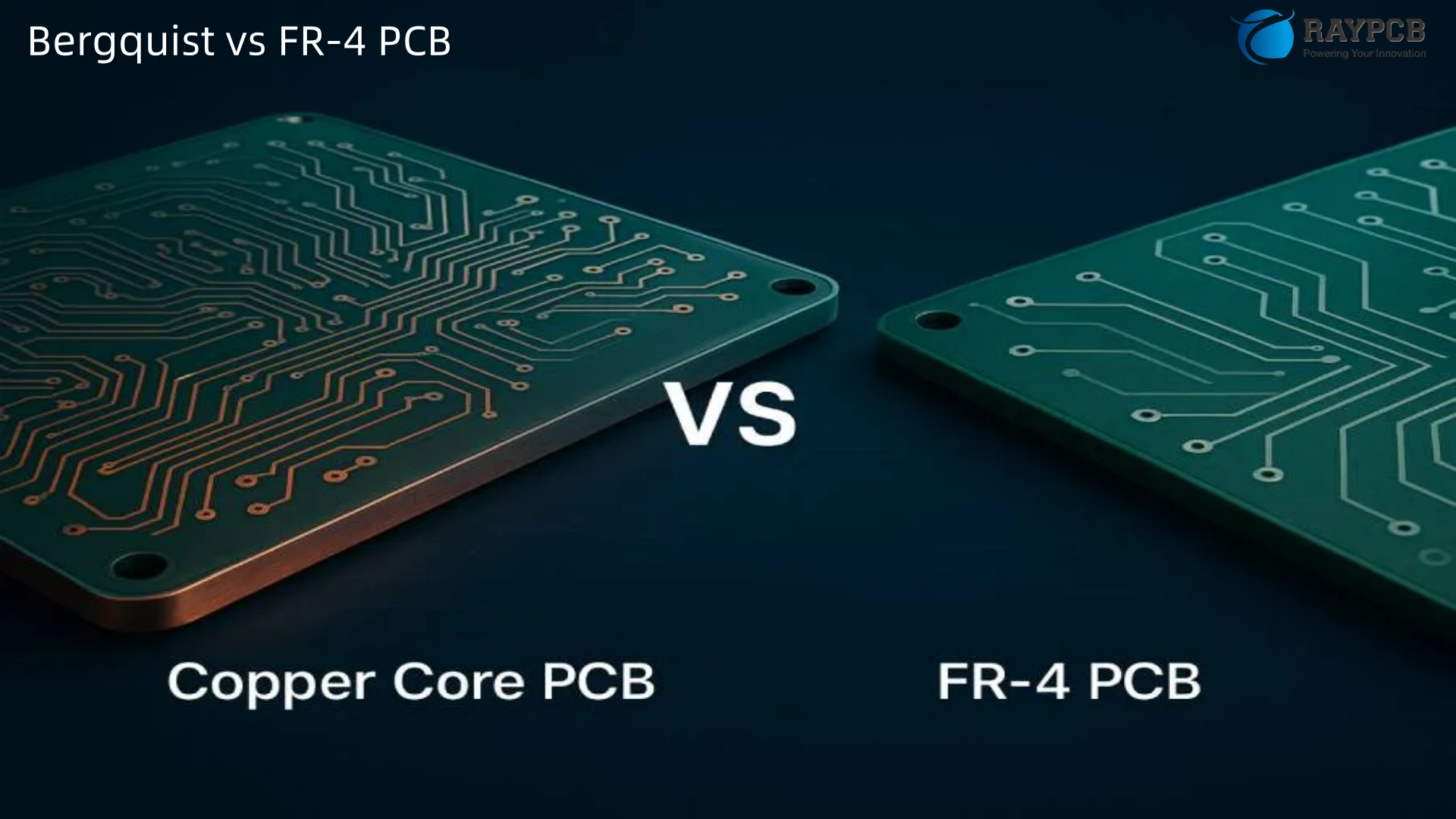
Against a standard epoxy prepreg MCPCB dielectric (typically 0.8โ€“1.0 W/mK), both HT grades offer roughly 2โ€“4ร— better thermal conductivity. Against FR-4 at 0.3 W/mK, the gap is even wider. For applications that previously relied on ceramic substrates (DBC, AMB), the HT series offers comparable thermal performance in an aluminum-based format that costs less and machines more easily.

Both grades support:

  • Eutectic gold-tin (Au80Sn20) solder for direct die attach
  • Lead-free reflow processes with standard SAC305 alloys
  • Selective dielectric removal (SDR) for pedestal and direct metal-contact configurations
  • Ultra Thin Circuit (UTC) constructions using Bergquist Bond-Ply 450 PA
  • All standard aluminum alloys (1000, 3000, 5000, 6000 series) and copper base metals
  • Base metal thicknesses from 0.5mm to 3.2mm

The shared UL 746B recognition at 140ยฐC continuous operating temperature and the 325ยฐC/60-second solder limit mean that production assembly processes do not need to differentiate between the two grades.

How HT-04503 and HT-07006 Compare to Other Thermal Clad Grades

Understanding where these two fit within the broader Bergquist lineup helps clarify when you might step outside the HT family entirely.

PropertyHPL-03015HT-04503HT-07006HT-09009MP-06503
Dielectric thickness1.5 mil / 38ยตm3 mil / 76ยตm6 mil / 152ยตm9 mil / 229ยตm3 mil / 76ยตm
Thermal resistance (ยฐCยทcmยฒ/W)0.300.450.710.900.58
Breakdown voltage (kVAC)~2.5~8.511.0~20.0~8.5
Tg (ยฐC)18515015015090
Primary useHigh-power LEDMid-voltage powerHigh-voltage powerVery high isolationGeneral purpose

If neither HT-04503 nor HT-07006 fits your spec, the HT-09009 steps up to 9 mil dielectric for systems requiring voltage isolation margins above what HT-07006 provides. At the low end, HPL-03015 delivers the best possible thermal resistance but is limited to lower voltage applications and has a lower dielectric thickness that mandates careful voltage derating.

Design Considerations Specific to Each Grade

Routing and Copper Weight

Both HT grades behave identically from a fabrication standpoint: standard SMT assembly, LPI solder mask, HASL or ENIG surface finish. Copper weights from 1 oz (35ยตm) through 3 oz (105ยตm) are standard; heavier copper is available on request. The 2 oz option is worth specifying for any trace carrying more than ~3A of continuous current, regardless of HT grade.

Component Placement Near Board Edge

With the HT-07006’s thicker dielectric, you get an additional mechanical benefit on boards where components sit close to the edge: slightly higher resistance to edge delamination under mechanical stress. It is a marginal difference for most designs, but relevant in vibration-exposed automotive underhood assemblies.

Thermal Via Strategy

Neither HT grade supports plated through-holes connecting to the base metal electrically. For high-power devices requiring the shortest possible thermal path, selective dielectric removal (SDR) creates a direct copper-to-aluminum contact window beneath the device footprint. This technique works equally well with both HT grades but is more commonly justified when using HT-07006 โ€” because the thicker dielectric represents a larger thermal resistance penalty that SDR can eliminate for the highest-dissipation components.

Comparing to Arlon PCB Materials

Engineers specifying high-temperature substrates sometimes evaluate Arlon PCB materials alongside Bergquist HT grades. Arlon’s thermoset products like the 85N and 91ML address high-temperature FR-4 replacement applications in multilayer boards, but they are fundamentally different โ€” glass-reinforced epoxy laminates rather than metal-core IMS. Arlon materials do not provide the metal-base thermal path that defines the HT-04503 and HT-07006 value proposition. If your design needs a drop-in FR-4 replacement with better Tg and thermal stability, an Arlon high-Tg laminate may be relevant. If you need to get heat out of a power device into a metal heatsink structure, that is firmly in Bergquist HT territory.

Useful Resources and Official Datasheets

Every engineer working with these materials should have the following documents open before finalizing a design:

ResourceDescriptionLink
Bergquist Thermal Clad Selection GuideComplete dielectric comparison, design rules, voltage guidelinesDigi-Key PDF
HT-04503 Datasheet (Bergquist/Henkel)Full property table for 3 mil HT dielectricmclpcb.com PDF
HT-07006 Datasheet (Bergquist/Henkel)Full property table for 6 mil HT dielectricmclpcb.com PDF
IPC-2221BGeneric Standard on Printed Board Design (voltage spacing tables)IPC.org
IEC 60664-1Insulation coordination โ€” essential for working voltage vs. dielectric thickness decisionsIEC Webstore
UL 796Standard for Printed Wiring Boards (solder limit rating reference)UL Standards
Henkel Electronics Materials (Bergquist)Manufacturer product page and distributor linkshenkel.com
Digi-Key Bergquist IMS ListingStocking distributor with live pricingDigi-Key

5 FAQs: HT-04503 vs HT-07006

Q1: Can I substitute HT-07006 for HT-04503 if my supplier is out of stock?

Technically yes, but with a thermal performance penalty. The HT-07006’s thicker dielectric increases thermal resistance from 0.45 to 0.71 ยฐCยทcmยฒ/W. Whether that matters depends entirely on how close your design is to its thermal limit. If you have margin, the swap is fine โ€” and the HT-07006 gives you better voltage isolation as a bonus. If your thermal model shows junction temperatures already within 10ยฐC of the component’s maximum, run the numbers again with the higher thermal resistance before approving the substitution.

Q2: Which grade should I use for a 240VAC motor drive?

HT-07006. The working voltage on a 240V AC system generates DC bus voltages of approximately 340V (peak), and safety agency requirements (IEC 62368, UL 508C) require meaningful clearance between the circuit potential and the chassis/heat sink ground. The HT-04503 at 8.5 kVAC breakdown will likely pass, but the HT-07006’s 11 kVAC rating and thicker dielectric provide a more robust safety margin for certification testing and field reliability.

Q3: Do I need to change my reflow profile when switching between HT-04503 and HT-07006?

No. Both materials share the same Tg (150ยฐC), the same UL solder limit (325ยฐC/60s), and the same epoxy chemistry. Standard lead-free SAC305 reflow profiles with peak temperatures of 245โ€“255ยฐC are compatible with both. The aluminum base metal has higher thermal mass compared to FR-4, so your profiling adjustment relates to the base metal thickness and mass, not the dielectric grade selection.

Q4: Is there a cost difference between HT-04503 and HT-07006?

In practice, HT-07006 panel stock typically costs slightly more than HT-04503 due to the higher dielectric material volume. The difference at PCB fabrication level is usually modest โ€” a few percent โ€” since substrate material is rarely the dominant cost driver once fabrication, copper, and finish are accounted for. If you are cost-optimized and voltage permits, HT-04503 is the leaner choice.

Q5: How do I determine which grade my existing board uses if there’s no BOM available?

Measure the board at its edge cross-section or request the dielectric thickness from the fabricator. The HT-04503 dielectric layer is nominally 76ยตm thick; the HT-07006 is 152ยตm. Even with copper and base metal variation, these differences are measurable with a calibrated micrometer on a board cross-section. You can also check the breakdown voltage โ€” apply a controlled dielectric withstand test (hi-pot test): the 8.5 vs 11 kVAC ratings will tell you which material you have.

Final Verdict: HT-04503 vs HT-07006

The bottom line is straightforward. These are not competing products โ€” they are complements within the same dielectric family addressing different points on the voltage-vs-thermal-performance curve.

HT-04503 wins when: operating voltage is below 480V AC or equivalent DC, thermal budget is tight, or you want the maximum thermal conductivity the HT chemistry can deliver.

HT-07006 wins when: the design involves mains-connected voltages, EV high-voltage buses, industrial 400/480V three-phase systems, or any application where safety certification demands more isolation distance than 76ยตm of dielectric can confidently provide.

Get the voltage isolation requirement nailed down first โ€” that determination typically locks the dielectric grade. Then optimize copper weight, base metal thickness, and mounting configuration around the thermal budget. That order of operations will keep you out of trouble on both dimensions.

HPL-03015 vs HT-04503: Choosing Between Bergquist High Power & High Temp Dielectrics

HPL-03015 vs HT-04503: detailed spec comparison, thermal vs isolation tradeoffs, application guide, and design tips for Bergquist Thermal Clad IMS PCB selection.

When you’re designing a metal core PCB and the Bergquist Thermal Clad lineup is on the table, two grades come up more than almost any other: HPL-03015 vs HT-04503. They’re both high-performance IMS dielectrics. They’re both lead-free compatible, RoHS compliant, and proven in demanding applications. But they are built for fundamentally different design priorities โ€” and picking the wrong one can cost you in thermal headroom, isolation margin, or board reliability down the line.

This guide breaks both materials down from an engineering standpoint: what the datasheets actually say, what the numbers mean in practice, and how to make the call when your design could arguably go either way.

What HPL-03015 and HT-04503 Actually Are

Both materials are dielectrics within Bergquist’s Thermal Clad Insulated Metal Substrate (IMS) family. The naming convention tells you the essentials: “HPL” stands for High Power Lighting, “HT” stands for High Temperature, and the trailing digits describe dielectric thickness โ€” 03015 means 3 mils at 0.0015 inches (38 ยตm), while 04503 means 3 mils at 0.003 inches (76 ยตm). That thickness difference is small on paper but significant in practice.

The HPL-03015 was developed specifically for high-brightness LED applications. It uses an extremely thin dielectric at 38 ยตm to minimize thermal resistance between the LED junction and the aluminum base layer. It achieves a thermal conductivity of 3.0 W/mยทK and thermal resistance of just 0.02ยฐCยทinยฒ/W โ€” numbers that put it at the top of the Thermal Clad dielectric performance ladder for raw heat transfer.

The HT-04503, by contrast, was designed around high-temperature durability and broad industrial applicability. It has a dielectric thickness of 76 ยตm (double the HPL), a dielectric thermal conductivity of 2.2 W/mยทK, and a glass transition temperature (Tg) of 150ยฐC. It’s proven in applications well beyond LED lighting โ€” motor drives, solid-state relays, power converters, heat rails, and solar receivers.

HPL-03015 vs HT-04503: Full Specification Comparison

This is the comparison table that most datasheets don’t provide side-by-side. Here it is in one place:

Thermal Properties

ParameterHPL-03015HT-04503Test Method
Dielectric Thermal Conductivity3.0 W/mยทK2.2 W/mยทKASTM D5470
Product Thermal Conductivityโ€”4.1 W/mยทKMET 5.4-01-40000
Thermal Resistance0.02ยฐCยทinยฒ/W0.05ยฐCยทinยฒ/WASTM D5470
Thermal Impedance0.30ยฐC/W0.45ยฐC/WMET-5.4-01-40000
Glass Transition Temperature (Tg)185ยฐC150ยฐCASTM E1356
Max Operating Temperature (UL)140ยฐC140ยฐCUL 796
Max Soldering Temperature325ยฐC325ยฐCUL 796

Electrical Properties

ParameterHPL-03015HT-04503Test Method
Dielectric Thickness0.0015 in / 38 ยตm0.003 in / 76 ยตmโ€”
Breakdown Voltage2.5 kVAC8.5 kVACASTM D149
Dielectric Strength2000 V/mil (75 kV/mm)2000 V/mil (80 kV/mm)ASTM D149
Dielectric Constant6.67.0ASTM D150
Dissipation Factor (1kHz/1MHz)0.003 / 0.0050.0033 / 0.0148ASTM D150
Capacitance925 pF/inยฒ540 pF/inยฒASTM D150
Volume Resistivity10ยนโด ฮฉยทm10ยนโด ฮฉยทmASTM D257
Operating Voltage (AC cont.)120 VACHigherโ€”

Mechanical & Agency Properties

ParameterHPL-03015HT-04503Test Method
Peel Strength @25ยฐCโ€”6 lb/in (1.1 N/mm)ASTM D2861
CTE XY/Z below Tgโ€”25 ยตm/mยฐCASTM D3386
Storage Modulus (@25ยฐC/150ยฐC)โ€”16/7 GPaASTM 4065
UL FlammabilityPendingV-0UL 94
CTIPending0/600IEC 60112
Lead-free solder compatibleYesYesโ€”
RoHS compliantYesYesโ€”

Note on HPL-03015 thermal conductivity: Some datasheets show 3.0 W/mยทK while product listings occasionally cite 7.5 W/mยทK. The 3.0 W/mยทK figure is the verified dielectric-only thermal conductivity per ASTM D5470 testing on the official Bergquist/Henkel datasheet. Always verify against the most current datasheet before finalizing a design.

The Core Engineering Difference: Thermal vs. Isolation Priority

Reading the table above, the choice between HPL-03015 vs HT-04503 really comes down to one fundamental tradeoff: thermal performance vs. electrical isolation headroom.

Why HPL-03015 Wins on Thermal Performance

The HPL-03015’s 38 ยตm dielectric is half the thickness of the HT-04503. Since thermal resistance is proportional to thickness divided by thermal conductivity, thinner is better for heat transfer. The result is a thermal resistance of 0.02ยฐCยทinยฒ/W compared to the HT-04503’s 0.05ยฐCยทinยฒ/W โ€” that’s 2.5ร— lower thermal resistance. In a high-density LED array, that difference directly translates to lower junction temperatures, longer LED lifetime, and more lumens per watt at steady state.

The HPL-03015 dielectric was specifically formulated for high power lighting LED applications with demanding thermal performance requirements. This thin dielectric at 0.0015″ (38ยตm) has the ability to withstand high temperatures with a glass transition of 185ยฐC and phenomenal thermal performance of 0.30ยฐC/W.

Why HT-04503 Wins on Isolation Voltage

The HT-04503 delivers a breakdown voltage of 8.5 kVAC โ€” compared to the HPL-03015’s 2.5 kVAC. That’s more than three times the isolation margin. Its thicker 76 ยตm dielectric is the reason: more dielectric material between the copper circuit and the aluminum base means more insulation.

The HT-04503 is a dielectric resistant to degradation from high temperature exposure and features high dielectric breakdown characteristics. This dielectric is proven in applications such as LED, Power Conversion, Heat-Rails, Solid State Relays and Motor Drives.

For AC mains-connected designs, industrial motor drives running from a 480 VAC bus, or any application requiring reinforced insulation under IEC 62368-1 or UL 508, the HT-04503’s isolation margin is non-negotiable. The HPL-03015 at 120 VAC continuous simply isn’t usable in those contexts regardless of how good its thermal numbers look.

Application-by-Application: Which Grade to Use

High-Power LED Lighting (Street, Architectural, Horticulture)

Winner: HPL-03015

This is the application HPL was literally named for. High-brightness LED arrays โ€” whether street fixtures, stadium lighting, or grow lights โ€” need the lowest possible thermal resistance between the LED die and the heatsink. Every degree of junction temperature rise reduces lumen output and accelerates lumen depreciation. The HPL-03015’s 0.02ยฐCยทinยฒ/W thermal resistance gives LED designers the most direct thermal path available in a polymer-based IMS dielectric.

The Tg of 185ยฐC also helps here. LED arrays in outdoor fixtures can see high ambient temperatures combined with self-generated heat, and a higher glass transition temperature gives additional confidence that the dielectric won’t soften and lose adhesion under worst-case thermal stress.

Automotive LED Headlamps and Backlighting

Winner: HPL-03015 (with caveats)

Automotive LED applications benefit from HPL-03015’s thermal performance and high Tg. The caveat is that automotive-grade designs may require documented UL CTI and flammability ratings โ€” values listed as “pending” on the HPL-03015 datasheet. If your automotive customer requires full UL 94 V-0 documentation, HT-04503 has those ratings confirmed, while HPL-03015 designs may need additional testing and documentation.

Industrial Motor Drives and Variable Frequency Drives (VFDs)

Winner: HT-04503

Motor drive inverter bridges operate from DC bus voltages ranging from 400 VDC to 800 VDC in modern industrial equipment. The continuous AC operating voltage limit of 120 VAC for the HPL-03015 rules it out immediately. HT-04503’s 8.5 kVAC breakdown and proven record in motor drives and solid-state relays make it the correct choice. The HT-04503 offers exceptionally low thermal resistance of only 0.05ยฐCยทinยฒ/W (0.32ยฐCยทcmยฒ/W), enabling effective heat dissipation and temperature control.

AC-DC Power Converters and Offline SMPS

Winner: HT-04503

Any offline switching power supply operating directly from 120 VAC or 230 VAC mains needs sufficient dielectric isolation between the primary-side switching devices and the chassis/heatsink. HT-04503 at 8.5 kVAC breakdown covers this with margin. HPL-03015 at 2.5 kVAC is inadequate for primary-side components on most mains voltages when safety standards are applied with derating.

DC-DC Converters (Low Voltage Bus, 12โ€“48 VDC Systems)

Winner: Either โ€” consider HPL-03015 if thermal is paramount

For isolated DC-DC converters operating at bus voltages below 48 VDC where isolation requirements are modest, HPL-03015 becomes viable again. If the primary design driver is junction temperature management in a space-constrained converter, HPL-03015’s superior thermal resistance makes it the better performer.

Solar Energy Systems and Concentrator PV

Winner: HT-04503

The HT-04503 is proven in solar receivers as well as power conversion and heat-rail applications. The higher isolation voltage and documented UL ratings make it more suitable for grid-tied solar inverter hardware where safety certifications are mandatory.

Comparing HPL-03015 and HT-04503 with Broader Thermal Clad Family Context

GradeDielectric ThicknessThermal ResistanceBreakdown VoltageTgPrimary Use
HPL-0301538 ยตm0.02ยฐCยทinยฒ/W2.5 kVAC185ยฐCHigh-power LEDs
HT-0450376 ยตm0.05ยฐCยทinยฒ/W8.5 kVAC150ยฐCIndustrial power, LEDs
HT-07006152 ยตm0.09ยฐCยทinยฒ/W11.0 kVAC150ยฐCHigh isolation, 480 VAC
MP-0650376 ยตm0.09ยฐCยทinยฒ/W8.5 kVAC90ยฐCCost-sensitive general purpose
CML-11006152 ยตm0.11ยฐCยทinยฒ/W>11 kVAC90ยฐCMulti-layer, max isolation

The HT-07006 is worth mentioning as a natural upgrade path from HT-04503 when you need more isolation voltage (for 480 VAC operation) while keeping the HT dielectric chemistry. It features even higher dielectric breakdown characteristics than the HT-04503, per the HT-07006 datasheet.

Comparing Bergquist IMS Materials vs. Arlon and Competitors

Engineers evaluating the HPL-03015 vs HT-04503 decision should also be aware of how Bergquist compares to alternatives. Arlon PCB materials represent another well-established IMS dielectric option, particularly for military and high-frequency power applications. Direct bond copper (DBC) on alumina outperforms both on thermal conductivity through the substrate but is brittle, fragile under mechanical stress, and significantly more expensive to fabricate. For most commercial power electronics where mechanical robustness and SMT assembly are priorities, Bergquist IMS remains a more practical solution.

Design Considerations for Both Materials

Copper Foil Weight

Both HPL-03015 and HT-04503 support copper foil from 1 oz to 10 oz (35โ€“350 ยตm). For LED lighting on HPL-03015, 1โ€“2 oz copper is typical. For high-current motor drive or power converter applications on HT-04503, 2โ€“3 oz copper is more common to keep trace temperature rise in check. Heavier copper also improves lateral heat spreading within the circuit layer itself โ€” a secondary thermal benefit.

Assembly and Reflow

Both materials specify a maximum soldering temperature of 325ยฐC and are compatible with standard SAC305 lead-free reflow profiles. The aluminum base layer adds thermal mass compared to FR-4 โ€” plan for a longer soak zone in your reflow profile to bring the board uniformly to reflow temperature, particularly for larger panel sizes or thicker aluminum bases (2.0 mm).

HiPot Testing

The capacitive nature of IMS construction means HiPot testing requires a controlled voltage ramp rate. For HPL-03015 especially, the high capacitance (925 pF/inยฒ) means fast ramp rates can trigger nuisance trips in isolation testers. Use a slow DC ramp, typically 100 V/second, and allow adequate dwell time at test voltage.

Board Routing and Fabrication

Both materials require carbide tooling for CNC routing and drilling through the aluminum base. Standard FR-4 routing parameters will cause rapid tool wear and aluminum burring. If you’re ordering from a fabricator, confirm they have experience with Bergquist IMS materials โ€” not all shops stock carbide tooling suited for metal-clad boards.

Useful Resources and Datasheets

ResourceDescriptionLink
Bergquist HPL-03015 Official DatasheetFull thermal, electrical, and mechanical spec tablemclpcb.com PDF
Bergquist HT-04503 Official DatasheetFull spec table with UL agency ratingsmclpcb.com PDF
Bergquist HT-07006 DatasheetFor higher isolation voltage variantmclpcb.com PDF
Bergquist Thermal Clad Selection GuideComplete dielectric comparison chart and design rulesDigikey PDF
Mouser HPL-03015 PDSAlternate source for HPL datasheetMouser PDF
Henkel Bergquist Product PortalCurrent product availability, ordering, custom configurationsHenkel Adhesives
IPC-2221 PCB Design StandardCreepage and clearance rules for voltage isolation designIPC.org
GlobalSpec HPL-03015 EntryThird-party spec listing with application notesGlobalSpec

5 FAQs: HPL-03015 vs HT-04503

Can I use HPL-03015 for an offline LED driver board operating from 120 VAC mains?

Technically no โ€” not for components with traces at mains potential. The HPL-03015 has a continuous AC operating voltage rating of only 120 VAC, and with standard derating practices applied, the usable operating voltage is considerably lower. The aluminum base is typically connected to chassis or safety ground in an offline driver, creating a high-voltage isolation requirement between primary-side circuitry and the base. HT-04503 at 8.5 kVAC breakdown is the appropriate choice for that interface. HPL-03015 is suited for the secondary-side LED array section of the driver, where voltages are typically well below its rating.

Which material runs cooler under an equivalent LED load โ€” HPL-03015 or HT-04503?

HPL-03015, and the gap is meaningful. With thermal resistance of 0.02ยฐCยทinยฒ/W versus HT-04503’s 0.05ยฐCยทinยฒ/W, the HPL dielectric introduces less than half the temperature drop per watt per unit area. For a typical 1 cmยฒ LED footprint dissipating 5W, that’s roughly a 1.5โ€“2ยฐC improvement through the dielectric alone. In LED system design where color consistency and lumen maintenance are tied to junction temperature, 2ยฐC matters.

Is the HPL-03015 Tg of 185ยฐC an advantage over HT-04503’s 150ยฐC?

For LED applications, yes. A higher Tg means the dielectric retains its mechanical properties at higher temperatures before softening. In high-ambient outdoor or automotive luminaires that also see significant self-heating, the HPL-03015 has more headroom before the dielectric transitions from glassy to rubbery behavior. That said, both materials share the same 140ยฐC UL maximum continuous operating temperature, so the Tg advantage of HPL-03015 is more about margins and reliability during stress events than normal operation.

What’s the difference between HT-04503 and HT-07006, and how do they relate to HPL-03015?

HT-07006 uses the same high-temperature HT dielectric chemistry as the HT-04503 but at 6 mils (152 ยตm) thickness instead of 3 mils. The thicker dielectric raises breakdown voltage to 11 kVAC and is appropriate for designs operating near 480 VAC. Its thermal resistance is 0.09ยฐCยทinยฒ/W โ€” higher than both HT-04503 and HPL-03015. The simple hierarchy for isolation voltage is: HPL-03015 (2.5 kV) < HT-04503 (8.5 kV) < HT-07006 (11 kV). For thermal performance it reverses: HPL-03015 > HT-04503 > HT-07006.

Are HPL-03015 and HT-04503 both available on copper base layers?

Yes. Both materials in the Bergquist Thermal Clad family are available on aluminum and copper metal substrates. Copper base provides approximately 2.4ร— better lateral heat spreading than aluminum (390 W/mยทK vs. 160 W/mยทK), which benefits high-density LED arrays on HPL-03015 and high-current bus bar designs on HT-04503. Copper base adds cost and weight โ€” it’s a meaningful choice for the highest watt-density applications but overkill for most standard designs.

Summary: Making the Call on HPL-03015 vs HT-04503

The decision between HPL-03015 vs HT-04503 isn’t complicated once you frame it correctly. Ask two questions about your design: what is the operating voltage relative to the aluminum base, and what is the primary thermal bottleneck?

If your design operates at voltages below 120 VAC at the board-to-chassis interface and thermal resistance is the dominant design concern โ€” LED street lighting, architectural fixtures, horticultural lighting, backlighting panels โ€” HPL-03015 is the right material. Its 0.02ยฐCยทinยฒ/W thermal resistance and 185ยฐC Tg give LED designers the best thermal path available in a Bergquist polymer IMS dielectric.

If your design involves mains-connected circuitry, industrial motor drives, DC bus voltages above 170 VDC, or any application where UL V-0 flammability documentation is mandatory, HT-04503 is the correct starting point. Its 8.5 kVAC breakdown, proven industrial application base, and full UL agency ratings make it a more complete solution for safety-critical power electronics designs.

Both materials are excellent products within their intended domains. The engineering mistake isn’t choosing one over the other โ€” it’s choosing the wrong one for the wrong application.

Bergquist PCB vs Laird vs AI Technology IMS: Competitive Comparison

Engineer’s comparison of Bergquist PCB vs Laird Tlam vs AIT Cool-Clad IMS: dielectric architecture, thermal resistance data, multilayer capability, automotive fit, and selection guide.

If you’re sourcing IMS PCB dielectric material for a new design and the spec simply says “thermally conductive aluminum PCB,” you’re in generic territory. The moment your application demands documented thermal performance, lot-traceable materials, or a published UL RTI rating, you’re shopping between named brands โ€” and the three names that come up most often in serious power electronics and LED thermal discussions are Bergquist (Henkel), Laird, and AI Technology (AIT).

This Bergquist vs Laird IMS PCB comparison is written for engineers who need to make an actual selection decision โ€” not a general overview of what IMS PCBs are, but a focused look at how these three product families differ in dielectric approach, thermal performance claims, application strengths, supply chain realities, and the factors that actually tip the decision one way or the other.

Understanding the Three Competitors: Company Context

Bergquist / Henkel โ€” The Market Incumbent

Bergquist’s Thermal Clad family has been the reference point for IMS PCB materials for decades. After Henkel acquired Bergquist, the product line continued under the Bergquist brand within Henkel’s electronics division. The product families most engineers know by name โ€” HPL, HT, MP, CML โ€” are all Bergquist Thermal Clad products. The brand carries significant weight in automotive and LED lighting supply chains because their material specifications are published, tested to IEC and UL standards, and supported by widespread fabricator stocking.

Laird โ€” The Tlam System Challenger

Laird’s IMS offering centers on the Tlam system โ€” a thermally conductive PCB platform built around their Tlam PP (prepreg) dielectric materials. Laird positions Tlam as a system, not just a dielectric film: the same prepreg technology is used for single-sided Tlam SS boards, double-sided Tlam DS cores, and multilayer hybrid FR4/Tlam constructions. Laird is better known outside the PCB world for their broader thermal interface materials (gap fillers, phase-change pads, Tgrease products), which means their IMS PCB system sometimes gets less engineering attention than it deserves in head-to-head evaluations.

AI Technology (AIT) โ€” The Flexible Dielectric Specialist

AI Technology, a New Jersey-based materials company, takes a different approach from both Bergquist and Laird. Their Cool-Clad IMS laminate family uses a flexible, non-woven dielectric insulating layer rather than the rigid ceramic-filled epoxy that both competitors use. AIT holds multiple US patents on this flexible thermal dielectric approach. The claimed advantages are zero internal stress, lower lamination pressure requirements (below 14 psi vs much higher for rigid dielectrics), and high-temperature stability to 300ยฐC โ€” important for reflow-intensive assembly processes and military or space applications where thermal cycling stress matters enormously.

Dielectric Technology Comparison: The Heart of the Difference

The dielectric layer is everything in IMS PCB performance. All three companies use ceramic fillers to push thermal conductivity above the 0.3 W/mยทK baseline of unfilled epoxy, but their filler systems, carrier materials, and mechanical philosophies diverge in ways that matter for specific applications.

Dielectric Architecture Side-by-Side

FeatureBergquist Thermal CladLaird TlamAIT Cool-Clad
Dielectric baseCeramic-filled epoxyCeramic-filled epoxyFlexible non-woven polymer
Filler systemProprietary ceramic blendCeramic (1KA, HTD grades)AlN, BN, Alโ‚‚Oโ‚ƒ blends
Glass fiber reinforcementNoNo (standard); availableNo (by design)
Lamination pressureStandard PCB pressStandard PCB pressLow-pressure (<14 psi)
Internal stressPresentPresentZero (patented claim)
High-temp reflow compatibilityTo ~260ยฐCTo ~260ยฐCTo 300ยฐC
Multilayer pre-preg availableBond-Ply / CML seriesTlam PP (freestanding)Cool-Clad pre-preg

AIT’s zero-internal-stress claim is the most significant architectural differentiator. Standard ceramic-filled epoxy dielectrics cure rigid and introduce residual stress between the copper foil, dielectric, and aluminum base โ€” stress that accumulates over thermal cycles and can eventually cause delamination. AIT’s flexible dielectric absorbs this stress. In theory (and backed by their patent literature), this gives their laminates better long-term reliability under severe thermal cycling than rigid-dielectric competitors. Whether that matters in practice depends entirely on your cycle count and temperature range.

Thermal Performance Data Comparison

This is where engineers want numbers. The complication is that Bergquist, Laird, and AIT don’t all measure thermal performance identically โ€” test method, sample geometry, and bondline thickness assumptions differ. Use these figures for order-of-magnitude comparison, not as interchangeable spec sheet values.

Thermal Conductivity and Resistance Comparison

Material / ProductThermal Conductivity (dielectric)Typical Dielectric ThicknessThermal Resistance (approx.)Breakdown Voltage
Bergquist HPL-030153.0 W/mยทK1.5 mil / 38 ฮผm0.09 ยฐCยทinยฒ/W2.5 kV AC
Bergquist HT-045032.2 W/mยทK3 mil / 76 ฮผm0.26 ยฐCยทinยฒ/W7 kV AC
Bergquist HT-090092.2 W/mยทK9 mil / 229 ฮผm0.90 ยฐCยทinยฒ/W20 kV AC
Laird Tlam PP 1KA~1.5โ€“2.0 W/mยทK3โ€“6 mil optionsComparable to HT series>5 kV DC
Laird Tlam PP HTD~1.5 W/mยทKUp to 9 milHigher isolation focus>5 kV DC
AIT Cool-Clad CXP~2.0โ€“3.0 W/mยทK3 mil / 75 ฮผmLow thermal resistance>3 kV
AIT Cool-Clad ESP~1.5โ€“2.0 W/mยทK75 ฮผmPerformance/reliability>3 kV

One note on Laird’s Tlam PP performance: Laird positions it as offering 8โ€“10x better thermal performance than FR4. Since standard FR4 sits at 0.3 W/mยทK, this implies roughly 2.4โ€“3.0 W/mยทK effective performance โ€” consistent with ceramic-filled epoxy systems in that thickness range. However, Laird’s published spec sheets are less granular than Bergquist’s on specific thermal resistance numbers, which can make direct comparison harder.

Application Fit: Where Each Brand Has Genuine Advantages

No single material brand wins every application. Here’s the honest breakdown of where each family tends to perform best in real design scenarios:

Bergquist Thermal Clad โ€” Best For Certified Product Development

The Bergquist advantage is not purely thermal โ€” it’s the documentation ecosystem around the product. Fabricators stock Bergquist material with lot traceability. UL certifications reference Bergquist product designations. Automotive Tier 1 suppliers often specify Bergquist by name in their approved material lists. When your board is going into a product that needs UL, CE, or automotive PPAP documentation, Bergquist’s established position in the compliance ecosystem reduces friction considerably. The Bergquist PCB material portfolio also covers the widest range of dielectric thicknesses, making it possible to match your isolation voltage requirement precisely rather than approximating.

Laird Tlam โ€” Best For System-Level Thermal Flexibility

Laird’s real advantage is in the Tlam system’s multilayer and hybrid flexibility. The fact that Tlam PP is available as a freestanding prepreg means it can be incorporated into multilayer stack-ups alongside standard FR4 cores โ€” a hybrid construction that puts thermally conductive dielectric exactly where the heat sources are while keeping standard FR4 cost elsewhere in the stack. For designers building power stages with complex control circuitry on the same board, this is genuinely useful. Laird’s 1KA prepreg works with copper foils from 0.5 oz to 4 oz and aluminum or copper base plates from 2.5mm to 6mm thick โ€” thicker bases than most Bergquist configurations.

Laird’s HTD variant specifically targets high withstand voltage (>5,000V DC) combined with 150ยฐC continuous operating temperature โ€” similar territory to Bergquist HT-09009, and a reasonable alternative for applications where direct Bergquist sourcing is constrained.

AIT Cool-Clad โ€” Best For Reliability-Critical and High-Temperature Assembly

AIT’s flexible dielectric approach is the most differentiated product in this comparison. The zero-stress claim, 300ยฐC reflow tolerance, and low lamination pressure enable applications that rigid dielectric systems handle poorly: boards that see 1,000+ severe thermal cycles, military and aerospace assemblies where delamination failure modes are unacceptable, and boards with heavy copper (3โ€“4 oz) where the CTE mismatch stress between thick copper and rigid dielectric is significant. AIT also explicitly supports die-attach and wire-bonding applications on their substrates โ€” making Cool-Clad relevant for COB (chip-on-board) LED modules and power module assemblies that Bergquist and Laird don’t optimize for.

The trade-off: AIT’s supply chain is narrower. Fewer fabricators stock or process AIT materials compared to Bergquist, which adds lead time for prototype orders. For volume production in well-qualified supply chains, this matters less.

Head-to-Head Scoring Matrix

Evaluation CriterionBergquist (Henkel)Laird TlamAIT Cool-Clad
Peak thermal conductivity availableโ˜…โ˜…โ˜…โ˜…โ˜† (4.5 W/mยทK)โ˜…โ˜…โ˜…โ˜†โ˜† (~2.0 W/mยทK)โ˜…โ˜…โ˜…โ˜…โ˜† (~3.0 W/mยทK)
Documentation / UL traceabilityโ˜…โ˜…โ˜…โ˜…โ˜…โ˜…โ˜…โ˜…โ˜†โ˜†โ˜…โ˜…โ˜…โ˜†โ˜†
Multilayer / hybrid flexibilityโ˜…โ˜…โ˜…โ˜†โ˜†โ˜…โ˜…โ˜…โ˜…โ˜…โ˜…โ˜…โ˜…โ˜…โ˜†
Thermal cycling reliabilityโ˜…โ˜…โ˜…โ˜†โ˜†โ˜…โ˜…โ˜…โ˜†โ˜†โ˜…โ˜…โ˜…โ˜…โ˜…
High-temperature reflow (>260ยฐC)โ˜…โ˜…โ˜†โ˜†โ˜†โ˜…โ˜…โ˜†โ˜†โ˜†โ˜…โ˜…โ˜…โ˜…โ˜…
Fabricator availability (global)โ˜…โ˜…โ˜…โ˜…โ˜…โ˜…โ˜…โ˜…โ˜†โ˜†โ˜…โ˜…โ˜†โ˜†โ˜†
Cost competitivenessโ˜…โ˜…โ˜…โ˜†โ˜†โ˜…โ˜…โ˜…โ˜†โ˜†โ˜…โ˜…โ˜…โ˜†โ˜†
Automotive supply chain presenceโ˜…โ˜…โ˜…โ˜…โ˜…โ˜…โ˜…โ˜…โ˜†โ˜†โ˜…โ˜…โ˜†โ˜†โ˜†
Voltage isolation optionsโ˜…โ˜…โ˜…โ˜…โ˜…โ˜…โ˜…โ˜…โ˜…โ˜†โ˜…โ˜…โ˜…โ˜†โ˜†

Supply Chain and Sourcing Considerations

One dimension engineers don’t always evaluate early enough is supply chain risk. All three brands have concentration risks:

Bergquist/Henkel: Broadly stocked, but a single Henkel plant outage or allocation issue can ripple through multiple fabricators simultaneously. Post-acquisition quality concerns occasionally surface in engineer forums โ€” verify that your fabricator is sourcing current production material and not old stock.

Laird: Now operating as Laird Performance Materials under DuPont after the 2019 acquisition. Organizational changes during large acquisitions sometimes create sourcing uncertainty. Confirm current stock and lead times directly with your fabricator before designing Tlam into a volume product.

AIT: Smaller company, US-based manufacturing, narrower distributor network. Lead time for initial prototype material can run longer than Bergquist. For volume production, AIT has qualified several contract fabricators โ€” worth confirming the approved fabricator list for your region.

Practical Selection Framework

If you’re making the Bergquist vs Laird IMS PCB decision right now, here’s the decision tree most experienced engineers use:

Application RequirementRecommended Material Family
Automotive, needs PPAP / UL file, high-voltage isolationBergquist HT series
General LED lighting, SELV-only, cost-sensitiveBergquist HPL or generic equivalent
Multilayer power + control board, hybrid FR4/IMSLaird Tlam PP 1KA
High-voltage isolation (>5kV DC) + 150ยฐC continuousLaird Tlam HTD or Bergquist HT-09009
Military, space, severe thermal cycling (>500 cycles)AIT Cool-Clad CXP or ESP
COB LED or die-attach process, 300ยฐC reflowAIT Cool-Clad
Heavy copper (3โ€“4 oz) with stress concernAIT Cool-Clad

For applications not matching one of these specific requirements, Bergquist’s broad stock availability and documentation ecosystem make it the lowest-risk starting point. Only switch to Laird or AIT when a specific performance or process requirement genuinely can’t be met with Bergquist.

Useful Resources for IMS PCB Material Comparison

ResourceWhat It Provides
Henkel / Bergquist Thermal Clad Selection GuideFull Bergquist product matrix including thermal, electrical, and UL data for HPL, HT, MP, and CML families
Laird Tlam Product PageLaird Tlam system overview, 1KA vs HTD prepreg comparison, multilayer application notes
AIT Cool-Clad IMS PageAIT Cool-Clad specifications, patent references, multilayer capability notes
IPC-4101 StandardBase material classification for metal-core laminates
IEC 62758Test methods for MCPCB thermal resistance โ€” the standard all three brands should be tested against
Saturn PCB ToolkitFree thermal resistance and trace width calculator to validate your stack-up choice

Frequently Asked Questions: Bergquist vs Laird IMS PCB

Q1: Can Laird Tlam PP prepreg be directly substituted for Bergquist Bond-Ply in a multilayer MCPCB design?

Structurally yes, both are thermally conductive B-stage prepreg films designed for multilayer assembly. However, lamination parameters differ โ€” cure temperature, pressure, and press time are material-specific. A direct substitution requires revalidating the lamination process with your fabricator. Also confirm that your isolation voltage requirement is met: Bergquist Bond-Ply products and Laird Tlam PP 1KA have different breakdown voltage specs at comparable thicknesses. Don’t assume equivalence without checking the datasheet for your specific thickness.

Q2: Does AIT Cool-Clad work with standard PCB fabrication processes or does it require specialty equipment?

AIT designed Cool-Clad specifically to work with standard PCB fabrication equipment, with one important difference: the lamination pressure is significantly lower than for rigid ceramic-filled dielectrics (below 14 psi vs typical PCB press pressures). Fabricators experienced with standard aluminum MCPCBs may need to adjust their press profiles. AIT provides fabrication guidelines directly and maintains a list of qualified fabricators. The 300ยฐC reflow tolerance means standard lead-free reflow processes work without modification.

Q3: Why is Bergquist so dominant in automotive IMS applications compared to Laird?

Bergquist’s automotive dominance is partly performance (the HT series covers the voltage and temperature requirements well) but mostly supply chain maturity. Automotive Tier 1 manufacturers built their PPAP documentation and qualification testing around Bergquist material. Substituting to Laird or AIT would require re-running qualification tests โ€” a costly and time-consuming process that nobody initiates without a strong reason. In new automotive designs not yet in production, the choice is more open, but Bergquist’s established qualification infrastructure gives it an institutional advantage.

Q4: Which brand offers the best thermal performance at the lowest total thermal resistance?

For minimum thermal resistance (best heat flow), AIT Cool-Clad CXP with a 75 ฮผm flexible dielectric at 2โ€“3 W/mยทK is competitive with Bergquist HPL at 3.0 W/mยทK over 38 ฮผm. The extremely thin Bergquist HPL-03015 (1.5 mil / 38 ฮผm) still offers the lowest thermal resistance in its class among standard products โ€” around 0.09 ยฐCยทinยฒ/W. The caveat is that HPL’s breakdown voltage is only 2.5 kV AC, limiting it to low-voltage applications. For applications needing both low thermal resistance and meaningful isolation voltage, AIT’s 75 ฮผm flexible dielectric represents a strong competing option.

Q5: Are there generic Chinese-sourced alternatives to Bergquist, Laird, and AIT that offer comparable performance?

Generic aluminum MCPCB laminates from Taiwanese and Chinese manufacturers (brands like Ventec, Iteq, and various OEM laminators) are widely used and cover most standard applications at lower cost. The functional gap between a reputable generic 2.0 W/mยทK dielectric and Bergquist HT is smaller than the price gap. Where the named brands are genuinely non-substitutable is in traceability and certification support. Generic laminates typically cannot provide the lot-traceable CoC with UL file references that Bergquist provides, and their long-term thermal cycling reliability data is less comprehensive. For commercial LED lighting, generic laminates are common and generally adequate. For automotive, industrial certified, or military designs โ€” the named brands are worth the premium.

Meta Description Suggestions:

Option A โ€” Keyword-rich, 155 characters: Bergquist vs Laird IMS PCB compared: thermal conductivity, dielectric technology, voltage isolation, supply chain, and application fit across Bergquist, Laird Tlam, and AIT Cool-Clad.

Option B โ€” Engineer-focused, 158 characters: Engineer’s comparison of Bergquist PCB vs Laird Tlam vs AIT Cool-Clad IMS: dielectric architecture, thermal resistance data, multilayer capability, automotive fit, and selection guide.

Option C โ€” Longer variant (~215 characters): Choosing between Bergquist, Laird Tlam, and AIT Cool-Clad for your IMS PCB design? This engineer’s guide compares dielectric technology, thermal conductivity, breakdown voltage, supply chain maturity, and application fit with a practical decision framework.

Bergquist Thermal Clad vs Standard FR-4: Why Metal Core PCB Wins for Thermal Management

Bergquist vs FR-4 PCB: engineer’s comparison of thermal conductivity, real heat calculations, application tables, and when metal core PCB is worth the cost.

Ask any power electronics engineer which substrate they reach for when a design pushes past 10โ€“15 watts of continuous dissipation, and the answer is rarely FR-4. That choice usually comes down to one number: thermal conductivity. Standard FR-4 sits at roughly 0.3 W/mK in the Z-axis. Bergquist vs FR-4 PCB comparisons tell the rest of the story โ€” Bergquist Thermal Clad dielectrics deliver 2.4 to 4.1 W/mK, and the aluminum or copper base underneath adds another zero to that figure entirely.

This article gets into the numbers honestly, covers the scenarios where FR-4 still makes sense, and explains why Bergquist Thermal Clad’s metal core architecture routinely outperforms FR-4 in high-power LED, power conversion, motor drive, and automotive applications.

Understanding the Core Problem: Why FR-4 Struggles with Heat

FR-4 is a glass-reinforced epoxy laminate โ€” and that same epoxy matrix that makes it such an effective electrical insulator is precisely what makes it a thermal bottleneck. At its core, FR-4 is an excellent electrical insulator but a poor thermal conductor. Its thermal conductivity is approximately 0.3 W/mK, and the same property making it a great electrical insulator also makes it a thermal barrier.

The problem compounds in the Z-axis, which is the direction heat actually needs to travel in a surface-mount assembly. The thermal conductivity path through the Z-axis is typically as low as 0.29 W/mK. Since heat generated by surface-mount devices must first pass vertically through this Z-axis insulating layer before reaching internal or bottom heat-dissipation planes, effective thermal management strategies must focus on bypassing this vertical bottleneck.

The consequence is predictable: In high-power applications, this can result in temperature rises of 50ยฐC or more above ambient conditions, risking component failure. Additionally, FR-4 has a glass transition temperature of around 130โ€“140ยฐC, beyond which it loses structural integrity, making it unsuitable for extreme heat environments.

Component life typically decreases according to the Arrhenius law as temperature rises โ€” a common empirical rule suggests lifespan approximately halves for every 10ยฐC increase in temperature. That rule of thumb is worth writing on the whiteboard before any high-power material selection discussion begins.

What FR-4 Engineers Do to Compensate โ€” And Why It Has Limits

Strategies for high-temperature FR-4 PCB designs include using thermal vias, incorporating heat sinks, and selecting complementary materials to reduce thermal resistance in FR-4. These workarounds are real and sometimes sufficient:

  • Dense thermal via arrays beneath power devices can reduce effective Z-axis resistance
  • Heavy copper (2โ€“4 oz) improves in-plane spreading
  • External heatsinks with TIM pads redirect heat away from the board
  • High-Tg FR-4 variants push the glass transition temperature to 170โ€“180ยฐC

But each workaround adds cost, assembly complexity, and board area. To compensate for its poor heat dissipation, FR-4 often requires external cooling solutions like heat sinks or forced air systems, increasing design complexity and cost. For applications pushing beyond 10โ€“15 watts of power dissipation per square inch, FR-4 often fails to meet thermal requirements, making IMS a better choice.

What Makes Bergquist Thermal Clad Different from FR-4

Bergquist Thermal Clad is an Insulated Metal Substrate (IMS) โ€” a fundamentally different architecture from FR-4. Bergquist’s Thermal Clad dielectric is a thin, thermally conductive layer bonded to an aluminum or copper substrate for heat dissipation. The key to Thermal Clad’s superior performance lies in its dielectric layer. This layer offers electrical isolation with high thermal conductivity and bonds the base metal and circuit foil together. Other manufacturers use standard prepreg as the dielectric layer, but prepreg doesn’t provide the high thermal conductivity and resulting thermal performance required.

The dielectric is a proprietary polymer/ceramic blend that gives Thermal Clad its excellent electrical isolation properties and low thermal impedance. The polymer is chosen for its electrical isolation properties, ability to resist thermal aging and high bond strengths. The ceramic filler enhances thermal conductivity and maintains high dielectric strength. The result is a layer of isolation which can maintain these properties even at 0.003″ (76ยตm) thickness.

The three-layer build โ€” copper circuit, ceramic-polymer dielectric, metal base โ€” creates a direct and controlled thermal path from solder joint to heatsink that FR-4 simply cannot replicate without significant added hardware.

Bergquist vs FR-4 PCB: Head-to-Head Material Properties

PropertyStandard FR-4High-Tg FR-4Generic MCPCBBergquist MP-06503Bergquist HT-04503Bergquist HPL-03015
Thermal conductivity (dielectric)0.3 W/mK0.35โ€“0.4 W/mK1.0โ€“2.0 W/mK2.4 W/mK4.1 W/mK~3.0 W/mK
Dielectric thickness100โ€“200 ยตm100โ€“200 ยตm100โ€“150 ยตm76 ยตm76 ยตm38 ยตm
Base thermal conductorNone (glass-epoxy)NoneAluminumAluminum or CopperAluminum or CopperAluminum or Copper
Glass transition (Tg)130โ€“140ยฐC170โ€“180ยฐC~130ยฐC90ยฐC150ยฐC185ยฐC
Max operating temp (UL)~130ยฐC~150ยฐC~130ยฐC~130ยฐC140ยฐC140ยฐC
Relative material costLowLowโ€“MediumMediumMediumMediumโ€“HighHigh
External heatsink required?Usually yesUsually yesSometimesRarelyRarelyRarely
RoHS / Lead-free compatibleYesYesVariesYesYesYes

The column that matters most in a thermal-limited design is the top one. At 4.1 W/mK (HT-04503), Bergquist’s dielectric is roughly 14ร— more thermally conductive than standard FR-4. In a substrate system where the dielectric layer is the dominant thermal resistance, that gap translates directly into cooler components.

The Real-World Thermal Impact: A Practical Comparison

The abstract conductivity numbers only become meaningful when you model them against an actual power stage. Consider a 25W MOSFET in a D2PAK package with a mounting footprint of approximately 1.5 cmยฒ. The junction-to-case resistance is 1.0ยฐC/W. You want to know the temperature rise across the substrate dielectric layer alone.

Using standard FR-4 (0.3 W/mK, 150ยตm thick):

ฮ”T (dielectric) = (Power ร— thickness) / (conductivity ร— area) = (25W ร— 0.00015m) / (0.3 W/mK ร— 0.00015 mยฒ) = 83ยฐC across the dielectric layer

Using Bergquist HT-04503 (4.1 W/mK, 76ยตm thick):

ฮ”T (dielectric) = (25W ร— 0.000076m) / (4.1 W/mK ร— 0.00015 mยฒ) = 3.1ยฐC across the dielectric layer

That 80ยฐC difference doesn’t come from a theoretical model โ€” it comes from the physical heat flow equation. In a high-power LED application, an IMS PCB can reduce the junction temperature of the LEDs by up to 20โ€“30ยฐC compared to FR-4 under the same operating conditions. Lower temperatures translate to better efficiency and a longer lifespan for the components.

Thermal Resistance: The Designer’s True Comparison Metric

Thermal resistance โ€” measured as ยฐC/W or ยฐCยทcmยฒ/W โ€” is the number to use when comparing designs, not conductivity alone. FR-4 typically has a thermal resistance of 50โ€“70 ยฐC/W per square inch, much higher than metal-core PCBs at around 10โ€“20 ยฐC/W.

SubstrateThermal Resistance (ยฐCยทcmยฒ/W)Notes
Standard FR-4 (1.6mm, no vias)50โ€“70Dominated by low Z-axis conductivity
FR-4 with dense thermal via array15โ€“25Improved but bulky layout penalty
Generic MCPCB (1.5 W/mK dielectric)1.5โ€“3.0Better, but grade-dependent
Bergquist MP-065030.58Consistent, well-characterized
Bergquist HT-045030.45High-temperature applications
Bergquist HPL-030150.30Optimized for LED die-attach

Where Bergquist Thermal Clad Wins by a Clear Margin

High-Power LED and Solid-State Lighting

This is where the Bergquist vs FR-4 PCB decision is most clear-cut. LED junction temperature directly controls lumen output, color point, and L70 lifetime (the point where output degrades to 70% of initial). The low thermal impedance of Thermal Clad dielectrics outperforms other PCB materials and offers a cost-effective solution, eliminating additional LEDs for simplified designs.

On a 100W street light array, the delta between FR-4 and Thermal Clad HPL is not just a thermal number โ€” it can mean the difference between an LED array lasting 50,000 hours versus 25,000 hours. Replacing burned-out fixture modules in a city-wide streetlight deployment has real maintenance cost implications that dwarf the material cost premium.

Motor Drives and Variable Frequency Drives

Bergquist’s Thermal Clad PCBs offer superior thermal conductivity, electrical insulation, and environmental compliance, making them ideal for motor drives where heat is a constant challenge. In a VFD, the IGBT or SiC MOSFET switch bank is the dominant heat source, and it cycles between full-on and off at switching frequencies from a few kHz to over 100 kHz. The thermal fatigue on the substrate dielectric under those conditions rules out standard FR-4 on reliability grounds, not just thermal performance grounds.

Automotive Power Electronics

As the automotive industry has shifted toward electric vehicles and advanced driver-assistance systems, these systems demand reliable electronic components that can withstand extreme environments, including fluctuating temperatures and vibrations. Bergquist PCBs handle components like inverters, battery management systems, and electronic control units with ease.

FR-4 is not absent from automotive electronics โ€” most ECU logic boards are FR-4 โ€” but the moment you cross into underhood power electronics with sustained dissipation above 5โ€“10W per square inch, the thermal and temperature-cycling fatigue limits of FR-4 push you toward an IMS solution.

Power Conversion and Solid-State Relays

Due to the size constraints and watt-density requirements in DC-DC conversion, Thermal Clad has become a favored choice. It can be used in almost every form-factor and fabricated in a wide variety of substrate metals, thicknesses, and copper foil weights.

In compact telecom converters or onboard chargers, eliminating the external heatsink assembly that FR-4 requires โ€” mica insulators, spring clips, thermal grease โ€” translates directly to lower BOM cost and fewer assembly steps. With the use of etched traces on the board, interconnects can be removed. This thermal clad helps to replace discrete devices at the board level and allows for increased power density.

Where FR-4 Is Still the Right Call

This is not a one-sided comparison. FR-4 earns its place in the vast majority of PCB designs for a reason.

ApplicationRecommended SubstrateRationale
Microcontroller logic boardsFR-4Low power dissipation; thermal non-issue
Signal processing / DSP boardsFR-4No high-power devices
RF/Microwave (low-loss req’d)Arlon PCB or RogersFR-4 loss tangent too high; Bergquist not optimized for RF
Consumer electronics (<5W)FR-4Cost wins; thermal adequate
LED driver logic sectionFR-4Power stage on Thermal Clad; logic on FR-4 panel attached via pin headers
High-power LED array (>10W)Bergquist Thermal CladThermal Clad HPL or HT wins decisively
Motor drive IGBT stage (>20W)Bergquist Thermal CladThermal + reliability requirements met
Automotive power moduleBergquist Thermal CladLM or HT depending on cycle count
EV inverter (>400V)Bergquist HT-07006Isolation voltage + thermal + reliability

For RF and microwave applications where loss tangent and dielectric constant stability matter more than thermal conductivity, FR-4 is also not the right call โ€” but neither is Bergquist Thermal Clad. That segment is where Arlon PCB materials (e.g., the AD and CLTE-XT series) are the correct specification. Knowing which of these three material families fits your design is the mark of a well-rounded PCB engineer.

Fabrication and Cost: Honest Trade-offs

Any honest comparison has to acknowledge the cost and process differences between FR-4 and Bergquist Thermal Clad.

Material and Fabrication Cost

Thermal Clad panel stock costs more than FR-4 โ€” sometimes substantially more depending on grade. The HT and HPL series are particularly premium. Beyond material, the fabrication process requires appropriate tooling: carbide drill bits rated for aluminum composite, single-flute CNC router bits to avoid galling, and depth-controlled V-scoring for clean panel singulation.

Design Complexity Trade-offs

Design FactorFR-4Bergquist Thermal Clad
Multilayer routingFull multilayer availablePrimarily single-layer circuit; 2-layer with Bond-Ply
Plated through-hole to base metalNot applicableNot standard (base is isolated)
External heatsink needed?UsuallyRarely
Thermal interface materials in BOMOften requiredEliminated
Pick-and-place assemblyStandardStandard โ€” same SMT process
Via drillingStandard platedNon-plated holes in metal; specialized tooling
Lead-free solder compatibleYesYes

Thermal Clad is a cost-effective solution which can eliminate components, allow for simplified designs, smaller devices, and an overall less complicated production process. Cooling with Thermal Clad can eliminate the need for heat sinks, device clips, cooling fans, and other hardware. An automated assembly method will reduce long-term costs.

The fabrication cost premium on Thermal Clad is partially offset by BOM simplification โ€” removing individual mica pads, spring clips, thermal grease application, and heatsink hardware from the assembly process. On high-volume production, that per-unit labor saving can be significant.

Useful Technical Resources for Bergquist vs FR-4 PCB Design

Every engineer comparing these materials at the design stage should have these documents bookmarked:

ResourceDescriptionLink
Bergquist Thermal Clad Selection GuideComplete dielectric family comparison, design rules, assembly guidelinesDigi-Key PDF
HPL-03015 DatasheetLED-optimized dielectric, 38ยตm, thermal resistance 0.30ยฐCยทcmยฒ/Wmclpcb.com PDF
HT-04503 DatasheetHigh temperature dielectric, 4.1 W/mK, 76ยตmmclpcb.com PDF
HT-07006 Datasheet6 mil HT dielectric, 11 kVAC breakdown, 0.71ยฐCยทcmยฒ/Wmclpcb.com PDF
MP-06503 DatasheetGeneral-purpose, 2.4 W/mK, 0.58ยฐCยทcmยฒ/Wmclpcb.com PDF
IPC-2221BGeneric Standard for Printed Board DesignIPC.org
IPC-4101Specification for Base Materials for Rigid and Multilayer PCBs (covers FR-4)IPC.org
JEDEC JESD51 SeriesThermal measurement standards for semiconductor devicesJEDEC.org
Henkel Bergquist Product PageCurrent product lineup, distributor links, SDS documentsHenkel Electronics

5 FAQs: Bergquist Thermal Clad vs FR-4 PCB

Q1: Can I use FR-4 with thermal vias instead of Bergquist Thermal Clad to save cost?

Sometimes yes, but with real limits. Dense thermal via arrays (via-in-pad, filled and capped) can reduce FR-4 thermal resistance meaningfully โ€” bringing it from 50โ€“70 ยฐCยทcmยฒ/W down to perhaps 15โ€“25 ยฐCยทcmยฒ/W for a well-designed via matrix. If your power dissipation is below ~5W per component and you have layout area to work with, this approach can work and costs less. Above that threshold, or in any design where board size is constrained, Thermal Clad’s consistent 0.30โ€“0.71 ยฐCยทcmยฒ/W performance and elimination of external hardware generally wins on total system cost and reliability. The thermal via approach also adds layout complexity and can compromise signal integrity around high-frequency switching nodes.

Q2: Is Bergquist Thermal Clad much harder to fabricate than FR-4?

It requires different tooling and process awareness, but it is not exotic. The aluminum base machines differently from glass-epoxy โ€” carbide drill bits wear faster, routing requires single-flute tools to prevent galling, and V-scoring depth requires tighter control. Standard SMT assembly, LPI solder mask, ENIG or HASL surface finish, and lead-free reflow profiles all transfer directly from FR-4 processes without modification. Any PCB fabricator regularly working with aluminum MCPCB has the right equipment. The main DFM consideration is getting the material spec note right on the drawing: base metal alloy, dielectric grade, copper weight, and any selective dielectric removal requirements.

Q3: Does Bergquist Thermal Clad support multilayer designs like FR-4?

Not in the same way. Standard FR-4 multilayer PCBs with 4, 6, or 8 layers are straightforward. Thermal Clad is primarily a single-circuit-layer substrate. Two-layer configurations are achievable using Bergquist Bond-Ply to laminate a second FR-4 or Thermal Clad circuit to the back of the base metal, but buried vias, blind vias, and standard multilayer constructions are not. For designs that need both high-power thermal management and complex multilayer routing, a hybrid approach is common: power devices on a Thermal Clad section, logic and control circuitry on a conventional FR-4 PCB, interconnected by press-fit pins or flex cable.

Q4: When does it make financial sense to upgrade from FR-4 to Bergquist Thermal Clad?

The crossover point depends on what FR-4 forces you to add to compensate for its thermal limitations. Count the BOM cost of individual TO-220/TO-247 insulators (mica or Kapton), thermal grease or phase-change TIM, heatsink hardware, and assembly labor for torqued fasteners. In a motor drive or power supply with six to twelve power devices, that hardware cost per board can easily reach $3โ€“8 in materials alone, plus the assembly time. Thermal Clad eliminates all of it. The material premium on the board itself is often recovered within the first several hundred units, and the reliability improvement โ€” particularly in warranty cost reduction โ€” frequently makes the financial case compelling even before you reach high volumes.

Q5: Can Bergquist Thermal Clad replace ceramic substrates like DBC?

Thermal Clad can replace large-area ceramic substrates. It can also be used as a mechanically durable support for ceramic spacers or direct bonded copper sub assemblies. The copper circuit layer of Thermal Clad has more current carrying capability than thick-film ceramic technology. For moderate-power applications โ€” say, up to 50โ€“100W single device โ€” the substitution of Thermal Clad for DBC (Direct Bonded Copper on alumina) is viable and typically reduces cost and brittleness risk. At very high power density with bare die mounting and tight thermal budgets, DBC or AMB (Active Metal Brazed) ceramics on aluminum nitride maintain an edge in bulk thermal conductivity. Thermal Clad sits between FR-4 and DBC in both performance and cost โ€” which happens to be exactly where most industrial and automotive power electronics designs live.

Final Thoughts on Bergquist vs FR-4 PCB

The Bergquist vs FR-4 PCB choice is not actually complicated once you run the thermal numbers. FR-4 is a superb material for the overwhelming majority of electronic designs where power dissipation is moderate and thermal management can be handled with copper planes and selective use of heatsinks. The moment a design needs to move more than roughly 10W per square inch through the substrate consistently, FR-4’s 0.3 W/mK Z-axis conductivity becomes the design’s weak link.

Bergquist Thermal Clad’s proprietary ceramic-polymer dielectric eliminates that weak link. The result โ€” direct junction-to-metal-base thermal conduction, no added TIM hardware, consistent and well-characterized thermal resistance values โ€” is precisely why it has been the benchmark MCPCB dielectric for LED, motor drive, power conversion, and automotive power electronics for decades.

Make the material decision early, run the thermal resistance stack calculation honestly, and choose the dielectric grade (HPL, HT, MP, or LM) that fits your voltage isolation and thermal budget. That order of operations will keep your design out of warranty returns and off the teardown bench.

The Complete Guide to Bergquist Thermal Clad PCB Materials [2025]

The complete engineer’s guide to Bergquist Thermal Clad PCB materials โ€” dielectric series comparison, design rules, thermal specs, FAQs, and official datasheet links for 2025.

If you’ve spent any time specifying materials for high-power LED drivers, motor control boards, or automotive power modules, you’ve almost certainly landed on Bergquist Thermal Clad PCB as a candidate material. It shows up in the datasheet for half the metal-core substrates on the market, and with good reason โ€” the dielectric technology behind it has been setting the benchmark for insulated metal substrates (IMS) for decades.

This guide breaks down everything a working PCB engineer needs to know: the dielectric series, real-world thermal numbers, design rules, fabrication gotchas, and when Thermal Clad genuinely outperforms the competition versus when a cheaper alternative will do the job just fine.

What Is Bergquist Thermal Clad PCB?

Bergquist Thermal Clad is a metal-core PCB (MCPCB) substrate technology developed by The Bergquist Company, now operating under Henkel Corporation’s Electronic Materials division and also carried by successor brands such as TCLAD Inc. At its core โ€” literally โ€” the product is a laminate stack: a copper circuit foil bonded through a proprietary thermally conductive dielectric layer to an aluminum or copper baseplate.

What makes it different from generic aluminum-base PCBs is that dielectric. The technology of Thermal Clad resides in the dielectric layer โ€” it is the key element for optimizing performance. The dielectric is a proprietary polymer/ceramic blend that gives Thermal Clad its excellent electrical isolation properties and low thermal impedance. The polymer is chosen for its electrical isolation properties, ability to resist thermal aging and high bond strengths. The ceramic filler enhances thermal conductivity and maintains high dielectric strength โ€” resulting in a layer of isolation that can maintain these properties even at 0.003″ (76ยตm) thickness.

In other words, competing MCPCB products often use standard prepreg as the dielectric. Other manufacturers use standard prepreg as the dielectric layer, but prepreg doesn’t provide the high thermal conductivity and resulting thermal performance required to help assure the lowest possible operating temperatures and brightest light output for high-intensity LEDs. That’s the core value proposition in a single sentence.

The Three-Layer Structure

Every Bergquist Thermal Clad board follows a consistent build:

LayerMaterial OptionsTypical Thickness
Circuit Layer (Top)1 oz, 2 oz, 3 oz copper foil35 ยตm โ€“ 105 ยตm
Dielectric LayerProprietary polymer/ceramic blend (HPL, HT, MP, LM)38 ยตm โ€“ 254 ยตm
Base Metal (Core)Aluminum (1000/3000/5000/6000 series) or Copper0.8 mm โ€“ 3.2 mm

The base metal is where the heat ultimately goes. Copper gives you better conductivity (390 W/mK), but aluminum is far more cost-effective at 205 W/mK and handles the thermal load in the overwhelming majority of commercial applications.

The Four Bergquist Thermal Clad Dielectric Series

This is the most important section for any engineer spec’ing a board. Thermal Clad circuit board materials are available from The Bergquist Company in four different thermal conductivities: High Power Lighting (HPL), High Temperature (HT), Low Modulus (LM), and Multi-Purpose (MP). Each is engineered for a specific operating envelope.

HPL โ€” High Power Lighting

HPL is the go-to dielectric for demanding LED applications. HPL is a dielectric specifically formulated for high power lighting LED applications with demanding thermal performance requirements. This thin dielectric at 0.0015″ (38ยตm) has an ability to withstand high temperatures with a glass transition of 185ยฐC and phenomenal thermal performance of 0.30ยฐC/W.

The part number most commonly seen in the field is HPL-03015, which refers to the 0.030″ (0.76mm) base aluminum thickness with 1 oz (35ยตm) copper. Bergquist Thermal Clad Metal Core PCBs minimize thermal impedance and conduct heat more effectively and efficiently than standard printed wiring boards.

When to use HPL: Any design where junction temperature is the dominant constraint โ€” high-wattage COB LEDs, stadium lighting, projector systems, and backlit display modules.

HT โ€” High Temperature

The HT series offers a balance of elevated operating temperature tolerance and strong thermal conductivity. The HT-04503 provides high thermal conductivity of 4.1 W/m-K for high temperature applications, is lead-free solder compatible, Eutectic AuSn compatible, RoHS compliant and environmentally green, and available on all aluminum and copper metal substrates.

The HT-07006 variant steps up the dielectric thickness to 0.006″ (152ยตm) while maintaining that same 4.1 W/mK conductivity, making it the right call when you need more electrical isolation โ€” say, above 480V AC systems. The HT-07006 features a very low thermal resistance of 0.71ยฐC-cmยฒ/W combined with high thermal conductivity of 4.1 W/m-K, and the product is certified RoHS compliant.

When to use HT: Power conversion, motor drives, inverters, and any system needing eutectic gold-tin solder compatibility or operation above 150ยฐC continuous.

MP โ€” Multi-Purpose

MP-06503 is the workhorse of the Thermal Clad lineup โ€” a cost-optimized general-purpose substrate covering a huge range of mid-power applications. With a thermal resistance of 0.58ยฐC-cmยฒ/W, MP-06503 provides efficient heat dissipation, ensuring optimal thermal management for electronic devices. It exhibits a thermal conductivity of 2.4 W/m-K, enabling efficient heat transfer across the PCB.

The technology of Thermal Clad resides in the dielectric. Optimal storage for the MP-06503 is 5 to 25ยฐC for a 12-month shelf life. Worth noting for anyone managing incoming materials.

When to use MP: Solid-state relays, power supplies, battery management modules, and mid-power LED modules where budget pressure is real but you still need something better than off-brand MCPCB stock.

LM โ€” Low Modulus

LM is a less commonly discussed variant but worth knowing. The lower modulus dielectric provides improved mechanical compliance, which matters when you have CTE mismatch concerns between a large component and the substrate. This is especially relevant in applications with severe thermal cycling, where a brittle dielectric can delaminate over time.

When to use LM: Automotive underhood applications, aerospace modules, or any design where the assembly will see hundreds of thermal cycles between cold soak and operating temperature.

Bergquist Thermal Clad Dielectric Quick-Reference Table

SeriesThermal ConductivityThermal ResistanceDielectric ThicknessKey Application
HPL~3.0 W/mK0.30ยฐC-cmยฒ/W38 ยตm (0.0015″)High-power LED, backlight
HT-045034.1 W/mK0.50ยฐC-cmยฒ/W102 ยตm (0.004″)High-temp, motor drives
HT-070064.1 W/mK0.71ยฐC-cmยฒ/W152 ยตm (0.006″)>480V isolation, inverters
MP-065032.4 W/mK0.58ยฐC-cmยฒ/W152 ยตm (0.006″)General-purpose, PSU
LM~2.0 W/mK~0.80ยฐC-cmยฒ/W203 ยตm (0.008″)High-cycle automotive

Values are nominal. Always verify against the specific product datasheet for your revision.

Bergquist Thermal Clad vs. FR-4 vs. Generic MCPCB

One of the most common engineering questions is: “Do I actually need Thermal Clad, or will a cheaper metal-core board do the job?” The answer depends entirely on your thermal budget.

Bergquist Thermal Clad Metal Core PCBs minimize thermal impedance and conduct heat more effectively and efficiently than standard printed wiring boards. The low thermal impedance of Thermal Clad dielectrics outperforms other PCB materials and offers a cost-effective solution eliminating additional LEDs for simplified designs and an overall less complicated production process.

Here’s how the materials stack up for a typical 40W power stage application:

ParameterFR-4 (1.6mm)Generic MCPCBBergquist Thermal Clad HTBergquist Thermal Clad HPL
Thermal Conductivity0.3 W/mK1.0โ€“2.0 W/mK4.1 W/mK~3.0 W/mK
Dielectric Thickness200 ยตm+100โ€“150 ยตm102โ€“152 ยตm38 ยตm
Max Continuous Temp130ยฐC (Tg)~130ยฐC150ยฐC+185ยฐC Tg
Lead-Free SolderYesYesYesYes
IPC / UL CertificationIPC-4101VariesUL, ISO 9001UL, ISO 9001
Relative CostLowMediumMedium-HighHigh

The numbers tell the story. If you’re running a 5W LED module, a decent generic MCPCB is probably sufficient. At 20W and beyond โ€” particularly if junction temperature headroom is tight โ€” the thermal conductivity gap between Bergquist and generic alternatives starts translating directly into either shorter LED lifespan or the need for a larger heatsink.

Thermal Clad can replace large-area ceramic substrates. It can also be used as a mechanically durable support for ceramic spacers or direct bonded copper subassemblies. The copper circuit layer of Thermal Clad has more current carrying capability than thick-film ceramic technology.

This makes Thermal Clad a direct substitute for DBC (Direct Bonded Copper) ceramics in moderate-power applications โ€” at a significantly lower fabrication cost.

Key Applications of Bergquist Thermal Clad PCB

LED Lighting โ€” The Primary Use Case

LED lighting has truly transformed how we light up our spaces, offering energy-efficient alternatives that stand the test of time. But as LEDs get more powerful and brighter, managing heat becomes a bigger concern. That’s where Bergquist Thermal Clad PCBs come in, providing the perfect fix for LED lighting designs.

The HPL dielectric series was specifically engineered for this market. Bergquist provides critical thermal management support for a myriad of power LED applications including medical, signage, signal, transportation, aircraft, automotive, security, portable, theatrical, commercial, residential, and street lighting applications.

For a street lighting or high-bay LED array running at 100W+, the thermal budget is unforgiving. Using HPL with a direct thermal path from LED emitter to aluminum heatsink โ€” with no thermal grease or TIM interface โ€” delivers measurably lower Tj compared to any standard FR-4 or generic MCPCB solution.

Automotive and EV Power Electronics

The automotive industry has seen a substantial shift toward electric vehicles (EVs) and advanced driver-assistance systems (ADAS). These systems demand reliable electronic components that can withstand extreme environments, including fluctuating temperatures and vibrations. Bergquist PCBs meet these challenges with their high thermal conductivity, reliability, and rugged construction. Bergquist PCBs are designed to handle components like inverters, battery management systems (BMS), and electronic control units (ECUs) with ease.

Underhood environments routinely see ambient temperatures above 100ยฐC combined with aggressive vibration profiles. The HT and LM series both address this โ€” HT for raw thermal performance, LM where fatigue life under thermal cycling is the constraint.

Power Conversion and Motor Drives

Bergquist thermal clad is a preferred choice for engineers for power conversion due to its watt-density and size. Motor drives are also ideal for Bergquist thermal clad โ€” they are good dielectric material and feature high watt density, enabling fabrication and installation of compact form factors into motor drives.

Switching power supplies, VFDs, and servo drives all pack high-current components (IGBTs, MOSFETs, diode bridges) into tight footprints. Thermal Clad eliminates the need for individual TO-220 or TO-247 insulators (mica, Kapton, silicone pads) under power devices โ€” the board itself provides the isolation, and the assembly simplification is real.

Industrial and Aerospace

TCLAD Insulated Metal Substrate (IMS) PCBs deliver high efficiency, exceptional durability, and long-term reliability for mission-critical electronics operating in the extreme conditions of aerospace and defense applications.

In harsh-environment applications, the UL certification and controlled manufacturing processes of Bergquist materials are often a procurement requirement, not just a nice-to-have.

Design Guide for Bergquist Thermal Clad PCB

Getting the most out of Thermal Clad starts at the design stage, not at the FAI.

Dielectric Selection and Thermal Budget

Before you pick a dielectric grade, run the numbers. The thermal path from component junction to ambient is a series of resistances. The Thermal Clad layer is just one of them. Your calculation should include:

  1. Junction-to-case resistance of the component (Rฮธjc from datasheet)
  2. Solder joint resistance (typically 0.1โ€“0.5ยฐC/W for SMD)
  3. Thermal Clad dielectric resistance (from the product spec)
  4. Base metal spreading resistance
  5. Thermal interface to heatsink (if applicable)
  6. Heatsink-to-ambient (Rฮธsa)

If your calculation shows Tj is within 10ยฐC of the component’s maximum at full load, you need either a lower-resistance dielectric (HPL vs. HT) or a thicker copper circuit layer.

Copper Circuit Layer Thickness

The copper circuit layer of Thermal Clad has more current carrying capability than thick-film ceramic technology. However, trace width still matters. The circuit layer is the component-mounting layer in Thermal Clad. Current carrying capability is a key consideration because this layer typically serves as a printed circuit, interconnecting the components of the assembly. On Thermal Clad, smaller lines will not overheat, but they will increase the waste thermal heat of the assembly.

Use 2 oz or 3 oz copper (70ยตm or 105ยตm) for power traces wherever possible. On Thermal Clad, the heat generated by IยฒR losses in copper traces conducts straight down through the dielectric โ€” which is a feature, not a bug.

Dielectric Thickness and Voltage Isolation

The relationship between dielectric thickness and working voltage is non-linear. For applications with an expected voltage over 480 Volts AC, Bergquist recommends a dielectric thickness greater than 0.003″ (76ยตm). This immediately rules out HPL (38ยตm) for mains-connected power stages above that threshold โ€” HT-04503 or HT-07006 becomes the correct choice.

Thermal Via and Copper Pour Strategy

Unlike multilayer FR-4 PCBs where thermal vias punch heat down through the board, Thermal Clad does not support plated through-holes in the traditional sense. The base metal is electrically isolated by the dielectric. What you can do:

  • Use large copper pours on the circuit layer directly beneath high-power components to spread heat laterally before it enters the dielectric
  • Implement selective dielectric removal (SDR) processes โ€” where the dielectric is locally removed to create direct copper-to-baseplate contact for critical die-attach applications. Bergquist has developed a process for selectively removing dielectric to expose the baseplate, which is used in advanced power module assembly.

Design Rule Quick Reference

ParameterRecommended Minimum
Conductor to board edge0.5 mm
Conductor to conductor (signal)0.15 mm
Conductor to conductor (power)Per IPC-2221 spacing table
Non-plated drilled hole (min)0.76 mm (0.030″)
Drilled/plated via hole (min)0.25 mm (0.010″)
Solder mask registrationยฑ0.1 mm
Edge connector chamfer45ยฐ recommended

Fabrication and Assembly Considerations

Drilling and Routing

Aluminum-base Thermal Clad machines differently from FR-4. Drill bits designed for FR-4 will work but wear faster. For production runs, use carbide bits specified for aluminum composite materials. Routing should use single-flute upcut bits to avoid aluminum galling on the tool. Punching is viable for simple shapes but requires careful die design โ€” the ceramic-filled dielectric can crack if punch clearance is excessive.

Solder Mask and Surface Finish

Standard liquid photoimageable (LPI) solder mask applies to Thermal Clad circuit layers without process modification. Surface finish options are similar to standard PCBs:

Surface FinishSuitability for Thermal CladNotes
HASL (lead-free)GoodStandard choice for most applications
ENIGExcellentPreferred for fine-pitch SMD and wire bonding
Immersion SilverGoodCost-effective alternative to ENIG
OSPLimitedShort shelf life; avoid for high-reliability
Eutectic AuSnHT series onlyConfirmed compatible per datasheet

Reflow Soldering

Standard SMT reflow profiles work on Thermal Clad. The aluminum base actually helps here โ€” its thermal mass smooths out temperature ramp rates across the board. Be aware that: (a) the high thermal conductivity means large heat sinks or ground pours may require profiling adjustment, and (b) component leads or packages with high CTE mismatch relative to aluminum can stress solder joints under thermal cycling. For critical reliability, validate your solder joint fatigue life with FEA if the board will see >1000 thermal cycles.

Wire Bonding and Direct Die Attachment

The HT dielectrics are UL solder rated at 325ยฐC/60 seconds, enabling Eutectic Gold/Tin solders โ€” which opens the door to direct die-attach processes used in power module assembly. Wire bonding is supported on appropriately finished pads. Wire bonding is a connection technique that utilizes the surface mount ability of a PCB. In thermal clad assembly, pin headers and pin connectors are very useful when attaching an FR-4 panel to a thermal clad assembly.

Bergquist Thermal Clad vs. Arlon PCB Materials

When evaluating high-performance PCB substrate families, engineers often compare Bergquist Thermal Clad against other specialty laminates. Arlon PCB materials โ€” particularly the AD/CLTE series โ€” occupy a different part of the design space: they target high-frequency RF and microwave applications rather than thermal management. If your design requires both RF performance and thermal management (say, a high-power amplifier module), you may end up using Arlon-class materials for the RF section and Thermal Clad for the power stage section within the same assembly.

The comparison table below covers the most common design scenarios:

CriteriaBergquist Thermal CladArlon AD-SeriesStandard FR-4
Primary strengthThermal managementRF/Microwave performanceGeneral-purpose cost
Thermal conductivity2.4โ€“4.1 W/mK0.3โ€“0.7 W/mK~0.3 W/mK
Dielectric constant (Dk)~4.5โ€“5.53.0โ€“10.2 (wide range)4.5
Loss tangent (Df)~0.01โ€“0.020.0009โ€“0.002 (low loss)~0.02
Base substrateMetal (Al or Cu)PTFE/ceramic or thermosetGlass-epoxy
Ideal applicationLED, power electronics, motor drivesRF amplifiers, antennas, radarGeneral electronics

Neither material is universally superior โ€” they solve different problems. Knowing when to reach for each is the mark of an experienced designer.

Where to Source Bergquist Thermal Clad Materials and PCBs

Raw Material Distributors (Panel Stock)

If you’re qualifying the material yourself or sending it to a contract manufacturer, the following sources stock Bergquist Thermal Clad laminates:

DistributorRegionLink
Digi-Key ElectronicsGlobaldigikey.com
Mouser ElectronicsGlobalmouser.com
Arrow ElectronicsGlobalarrow.com
Henkel / Bergquist DirectGlobalhenkel.com
TCLAD Inc.US / Europe / Asiatclad.com

Useful Technical Resources and Datasheets

Below is a curated list of official and reference documents that should be bookmarked by any engineer working with Bergquist Thermal Clad PCB:

ResourceDescriptionLink
Thermal Clad Selection GuideComplete dielectric selection, design rules, and assembly guidelinesDigi-Key PDF
HPL-03015 DatasheetTechnical data for the High Power Lighting dielectricmclpcb.com PDF
HT-04503 DatasheetHigh Temperature 4.1 W/mK dielectric datamclpcb.com PDF
HT-07006 DatasheetHigh Temperature, 0.006″ thick dielectricmclpcb.com PDF
MP-06503 DatasheetMulti-Purpose dielectric datamclpcb.com PDF
IPC-2221Generic Standard for Printed Board Design (for trace/spacing rules)IPC.org
IPC-4562Copper foil specification (relevant for circuit layer thickness)IPC.org
LED Thermal Solutions GuideBergquist application guide for LED thermal managementHenkel-dam PDF

Pros and Cons of Bergquist Thermal Clad PCB

No material is perfect. Here is an engineer’s honest assessment:

Advantages

Bergquist thermal clad PCBs feature low thermal impedance which outperforms other insulators, allowing cooler operation. These thermal clad PCBs increase the level of durability because designs are simple and components run cool. The thermal clad removes the thermal interface and uses thermal solder joints, making assemblies run cooler. These thermal clad PCBs allow automated pick-and-place for SMDs, which minimizes production costs. Bergquist thermal clad minimizes board space and replaces other components like heat sinks, and helps eliminate rubber or mica insulators under power devices.

In practical terms this means: fewer BoM lines (no individual component TIMs), simplified assembly (no hardware-torqued insulators), and PCB-level thermal management that scales cleanly from prototype to production.

Disadvantages and Limitations

  • Cost:ย Panel stock is significantly more expensive than FR-4, and fabrication costs are higher due to specialized tooling and process parameters.
  • No plated through-holes to the baseplate:ย You cannot create a conventional electrical via to the base metal. All electrical routing is on the circuit side, which limits you to single-layer or specially configured two-layer constructions.
  • Dielectric thickness limitation on voltage rating:ย HPL’s ultra-thin dielectric limits isolation voltage โ€” it is not suitable for line-voltage isolation on its own at high power levels.
  • Panelization and singulation:ย V-scoring works but requires controlled depth. CNC routing with appropriate tooling is preferred for clean edges.
  • Heavier than FR-4 equivalents:ย The aluminum base adds weight โ€” a consideration in portable, wearable, or aviation-certified applications.

Common Mistakes Engineers Make with Bergquist Thermal Clad PCB

Based on the types of failures that show up in field returns and DFM reviews, these are the problems worth specifically avoiding:

1. Treating it like FR-4 in the Gerber package. Thermal Clad requires specific fabrication notes: base metal type and thickness, dielectric grade, copper weight, surface finish, and any selective dielectric removal areas. A generic FR-4 fab note set will result in the wrong board.

2. Ignoring the CTE mismatch between large SMD components and the aluminum base. Aluminum has a CTE of approximately 23 ppm/ยฐC; ceramic capacitors and large IC packages are typically 6โ€“10 ppm/ยฐC. Large ceramic caps (2220 size and above) mounted on aluminum MCPCB boards are fatigue-failure candidates in thermal-cycling applications. Size down, use polymer caps, or add strain relief in the layout.

3. Using HPL for designs above 480V. The 38ยตm dielectric is not appropriate for high-voltage isolation. Refer to IEC 60664-1 for full creepage and clearance requirements and select HT-04503 or HT-07006 accordingly.

4. Forgetting that the base metal is thermally โ€” but not always electrically โ€” isolated. Some designs unintentionally create a ground connection to the chassis through the mounting hardware. If your base metal must be floating, use insulated standoffs.

5. Over-tightening assembly screws. Aluminum is softer than steel. Use torque specs from your hardware supplier and avoid steel screws without proper thread inserts in the board.

FAQs About Bergquist Thermal Clad PCB

Q1: What is the difference between Bergquist Thermal Clad and a standard aluminum PCB?

The defining difference is the dielectric layer. A standard aluminum-base PCB uses conventional epoxy prepreg (similar to FR-4) as the insulating layer between the circuit copper and the aluminum core. Bergquist Thermal Clad uses a proprietary polymer/ceramic compound that delivers 4โ€“10ร— the thermal conductivity of standard prepreg. This translates directly into lower component operating temperatures for the same power dissipation level, or smaller/lighter board solutions for the same thermal budget.

Q2: Can Bergquist Thermal Clad PCB be used in multilayer designs?

Yes, with some caveats. Bergquist thermal clads aren’t only incorporated with metal base layers โ€” these substrates can boost their function by replacing FR-4 in multilayer assemblies. A common two-layer configuration bonds a standard FR-4 or Thermal Clad circuit to the back of the Thermal Clad base using Bond-Ply adhesive. This gives you two routing layers while maintaining the metal-base thermal path. True buried via multilayer constructions are not standard for Thermal Clad.

Q3: Is Bergquist Thermal Clad RoHS and REACH compliant?

Yes. The HT series is RoHS compliant and environmentally green. The same applies across the HPL and MP families. All current Bergquist Thermal Clad products are lead-free solder process compatible and meet the material restriction requirements of RoHS 2 and REACH. Always request a current compliance declaration from your supplier, as formulations can be updated.

Q4: How does Bergquist Thermal Clad perform in thermal cycling tests?

Thermal Clad substrates are well-characterized for reliability. Bergquist PCBs are designed to handle the demands of electric vehicles or industrial machines, including fluctuating temperatures and vibrations. Bergquist PCBs meet these challenges with their high thermal conductivity, reliability, and rugged construction. For the most demanding thermal cycling requirements (e.g., AEC-Q200 automotive qualification), the LM (Low Modulus) dielectric variant is specifically formulated for improved fatigue resistance. For typical commercial or industrial applications (โˆ’40ยฐC to +85ยฐC, ~500 cycles), standard HT or MP materials perform well without special consideration.

Q5: Who makes Bergquist Thermal Clad PCBs now, and is it the same product?

The Bergquist Company was acquired by Henkel Corporation and integrated into their Electronic Materials division. The Bergquist TCLAD products are now manufactured and supplied through Henkel Corporation. TCLAD Inc. is a separate company that has developed its own IMS technology continuing in the same product space. The core dielectric technology principles remain consistent, but engineers specifying Bergquist materials by name should request the Henkel Bergquist branded product or verify equivalency testing if substituting a TCLAD Inc. product. The part number naming convention (HPL-03015, HT-04503, etc.) has been preserved through the Henkel era.

Final Thoughts

Bergquist Thermal Clad PCB has earned its reputation by solving a real engineering problem โ€” getting heat out of dense, high-power electronics โ€” with a material that is manufacturable at scale, certifiable for safety agencies, and well-understood by the PCB supply chain. The four dielectric families (HPL, HT, MP, LM) give engineers enough granularity to optimize for cost, thermal performance, or mechanical robustness depending on the application.

The real skill is knowing when to reach for it. For a 3W LED nightlight, it is overkill. For a 150W EV charging module expected to survive 10 years and 2,000 thermal cycles, it is the right tool. Getting that judgment right โ€” and then executing the design with the correct grade, copper weight, and assembly process โ€” is what separates a board that runs cool and reliable from one that comes back in a warranty claim.

Use the datasheets and design guides linked above, run the thermal resistance calculations, and remember that the dielectric grade selection is one of the most leverage-heavy decisions in the entire design. Get that right, and the rest tends to follow.

Have a design challenge with Bergquist Thermal Clad PCB materials? Drop your questions in the comments or reach out to a qualified PCB manufacturer who can help with material selection and DFM review.

Bergquist Thermal Clad PCB FAQ: 25 Most Asked Questions Answered

Get straight answers to 25 of the most common Bergquist thermal clad FAQ questions โ€” from dielectric grades and thermal resistance to soldering, voltage ratings, and finding genuine TCLAD suppliers. Engineer-written, datasheet-backed.

If you’ve spent any time specifying IMS boards for LED or power electronics designs, you’ve almost certainly hit the same wall of questions that every engineer hits the first time through: What’s the actual difference between HT and HPL? Can this material handle a standard lead-free reflow profile? Do I really need a soldermask? What happened to Bergquist after Henkel acquired them?

This Bergquist thermal clad FAQ compiles the 25 questions that come up most often โ€” from materials engineers evaluating the technology for the first time to experienced designers troubleshooting a production issue. Answers are drawn directly from the TCLAD selection guide, published datasheets, and real fabrication experience. No filler, no padding โ€” just the answers.

Section 1: Material and Technology Fundamentals

Q1. What exactly is Bergquist Thermal Clad, and how does it differ from a standard aluminum PCB?

Thermal Clad is an Insulated Metal Substrate (IMS) technology built around a proprietary polymer-ceramic dielectric layer bonded between a copper circuit layer on top and an aluminum (or copper) base beneath. The technology of Thermal Clad resides in the dielectric โ€” a polymer chosen for its electrical isolation properties and ability to resist thermal aging, combined with a ceramic filler that enhances thermal conductivity while maintaining high dielectric strength.

The critical difference from generic aluminum PCBs is that standard aluminum boards use conventional prepreg as the dielectric, which achieves 1.0โ€“2.0 W/mยทK thermal conductivity. The TCLAD dielectric achieves up to 7.5 W/mยทK in the HPL-03015 grade โ€” a 4ร— to 7ร— improvement. That performance gap translates directly to lower LED junction temperatures, longer component lifetime, and the ability to run higher watt density without exceeding thermal limits.

Q2. What does the part number mean โ€” for example, HPL-03015 or HT-04503?

The part number encodes three pieces of information:

Part Number SegmentWhat It MeansExample (HPL-03015)
First lettersDielectric familyHPL = High Power Lighting
Middle three digitsThermal resistance ร— 100 (ยฐCยทinยฒ/W)030 = 0.30 ยฐCยทinยฒ/W
Last two digitsDielectric thickness in tenths of mils15 = 1.5 mils (38 ยตm)

So HT-04503 means: High Temperature dielectric, 0.45 ยฐCยทinยฒ/W thermal resistance, 3 mils (76 ยตm) thick. Once you internalize this convention, you can decode any Thermal Clad part number without opening a datasheet.

Q3. What dielectric families are available in the Thermal Clad lineup?

The main commercial families are: HPL (High Power Lighting) optimized for maximum thermal performance at low voltage, HT (High Temperature) offering a balance of thermal performance and high dielectric breakdown up to 6โ€“11 kV depending on thickness, MP (Multi-Purpose) for general purpose cost-sensitive designs, and LM (Low Modulus) for formable applications where the substrate needs to be mechanically shaped after assembly. HT-04503 and MP-06503 are the most widely stocked at fabricators. HPL-03015 requires more lead time at most shops.

Q4. Is Bergquist still the manufacturer, or has the brand changed?

The short version: the material now comes from TCLAD Inc. The Bergquist Company originally developed Thermal Clad, then Bergquist was acquired by Henkel in 2014. In 2021, Polytronics Technology Corp. acquired the Thermal Clad product line from Henkel and formed TCLAD Inc., a Delaware corporation. Manufacturing remains at the 100,000 sq. ft. Innovation Center in Prescott, Wisconsin, with operations also in Frankfurt, Germany and Hsinchu City, Taiwan. All original personnel and part numbers carried over. “Bergquist thermal clad” remains the common industry reference term for the technology, but the official brand is now TCLAD.

Q5. What is the thermal conductivity of Bergquist Thermal Clad, and how is it measured?

Thermal conductivity varies by dielectric grade. The table below summarizes the main grades:

DielectricThermal ConductivityDielectric ThicknessThermal Resistance
HPL-030157.5 W/mยทK38 ยตm / 1.5 mil0.30 ยฐC/W
HT-045032.2 W/mยทK76 ยตm / 3 mil0.45 ยฐC/W
HT-070062.2 W/mยทK152 ยตm / 6 mil0.70 ยฐC/W
LM-045031.7 W/mยทK76 ยตm / 3 mil0.45 ยฐC/W
MP-065031.3 W/mยทK76 ยตm / 3 mil0.65 ยฐC/W

Measurement uses two ASTM test methods: ASTM D5470 (steady-state method, direct derived value) and ASTM E1461 (Laser Flash diffusivity, from which conductivity is calculated). Both are referenced in TCLAD datasheets. It’s worth noting that the two methods can yield slightly different values due to their differing assumptions, which is why TCLAD datasheets specify the test method alongside the conductivity figure.

Q6. What does “unit thermal resistance” mean versus “thermal resistance” on the datasheet?

These are related but not interchangeable. Unit thermal resistance (ยฐCยทinยฒ/W) is a material property normalized per unit area โ€” use this to calculate the actual resistance for your specific component footprint. Thermal resistance (ยฐC/W) in most TCLAD datasheets refers to the resistance measured across a 1 inยฒ test area.

The working formula: R_dielectric (ยฐC/W) = Unit Thermal Resistance (ยฐCยทinยฒ/W) รท Component Pad Area (inยฒ)

For a 5mm ร— 5mm LED pad (0.025 inยฒ) on HPL-03015: R = 0.02 รท 0.025 = 0.8 ยฐC/W. On HT-04503: R = 0.05 รท 0.025 = 2.0 ยฐC/W. That 1.2 ยฐC/W difference at 3W dissipation means 3.6ยฐC hotter junction temperature on HT vs HPL โ€” significant when you’re managing LED lifetime.

Q7. What base metal options are available, and when would you use copper instead of aluminum?

Aluminum base (1100 alloy or equivalent) is standard and covers the vast majority of LED and power electronics applications. It’s lightweight, cost-effective, and thermally adequate for most designs. Copper base is available and offers higher thermal conductivity and better CTE matching to ceramic and bare die assemblies โ€” but it comes at significantly higher cost. Per the TCLAD selection guide, 0.125″ (3.18mm) aluminum base is equivalent in cost to 0.040″ (1.0mm) copper base. Choose copper base when you need maximum lateral heat spreading, direct die attachment, or CTE compatibility with ceramic substrates. For most LED applications, aluminum is the right call.

Section 2: Design and Layout Questions

Q8. What are the key circuit design guidelines for Thermal Clad boards?

The TCLAD selection guide publishes recommended circuit design limits for standard fabrication:

Design ParameterMinimum RecommendedNotes
Conductor width0.004″ / 100 ยตmEtching process limitation
Conductor spacing0.004″ / 100 ยตmDielectric isolation requirement
Conductor to board edge0.040″ / 1.0 mmMechanical and isolation margin
Solder mask coverageMandatoryRequired per UL and isolation
Copper weight range0.5 oz to 4 oz1 oz standard for LED
Minimum drill diameter0.020″ / 0.5 mmAluminum machining limitation

Note that use of a soldermask is mandatory on Thermal Clad โ€” this isn’t optional. It’s required for UL compliance and for maintaining adequate voltage isolation at conductor edges.

Q9. Do you need thermal vias on a Thermal Clad board?

Generally no, and in most single-layer IMS designs they can actually be counterproductive. On IMS PCBs, thermal vias can be problematic since the drill penetrates through the aluminum base and isolation must be maintained through the via annular ring. The aluminum itself handles heat spreading far better than an array of via copper can. The whole point of an IMS board is that the base metal spreads heat laterally to the heatsink contact area โ€” vias in FR-4 are a workaround for the absence of that spreading. Don’t add thermal vias to a Thermal Clad board unless there is a specific electrical reason (not thermal) to connect layers.

Q10. Can Thermal Clad boards be used in multi-layer configurations?

Yes, but it’s a specialty application. TCLAD describes configurations using Bergquist dielectrics bonded to a metal base with FR-4 type circuits or Thermal Clad circuits, depending on thermal requirements and cost objectives. Multi-layer Thermal Clad assemblies are less common than single-layer designs and require more specialized fabrication. For most LED and power supply designs, single-layer IMS is adequate and significantly simpler to fabricate and inspect. Contact TCLAD directly for guidance if your application genuinely requires a multi-layer IMS stack.

Q11. What is the minimum conductor-to-board-edge distance on Thermal Clad?

The standard recommendation from the TCLAD selection guide is 0.040″ (1.0mm) minimum from any conductor to the board edge. This accounts for both electrical isolation and the mechanical stress that occurs at the routed edge. If you’re using edge connectors, a 45ยฐ chamfer at the connector edge is recommended โ€” and the minimum conductor-to-edge distance must still be maintained along the chamfered section. This is one of those design details that often gets overlooked in the Gerber review and causes rework on first prototypes.

Q12. What copper weight should I specify for an LED board?

For most LED designs, 1 oz copper (35 ยตm) is the standard and most cost-effective choice. Thermal Clad trace interconnects can actually carry higher currents than equivalent FR-4 traces of the same width because the base metal dissipates the IยฒR heating more effectively. Where you need higher current-carrying capacity โ€” motor drive bus bars, high-current LED strings โ€” 2 oz or 3 oz copper is available. Heavy copper requires modified etching chemistry and longer etch times, which your fab house needs to account for in DFM review. Specifying 2 oz on a board that only needs 1 oz adds cost without any thermal benefit, so run the trace width calculation from IPC-2221 first.

Section 3: Assembly and Soldering

Q13. Is Bergquist Thermal Clad compatible with standard lead-free reflow profiles?

Yes, with some attention to profile management. TCLAD boards are compatible with standard SAC305 lead-free reflow โ€” peak temperatures in the 240โ€“260ยฐC range for 30โ€“60 seconds are within the dielectric’s rating. The TCLAD selection guide notes the material is rated at 325ยฐC/60 seconds for eutectic gold/tin solders, so standard lead-free profiles are well within limits. The key consideration for IMS reflow is that the aluminum base has significantly higher thermal mass than FR-4, which means your board takes longer to reach peak temperature and your oven profile needs to account for that. Profile validation on the actual board with thermocouples is essential, not optional.

Q14. What solder thickness is recommended for Thermal Clad assemblies?

The TCLAD selection guide specifies a minimum solder thickness of 0.004″ (100 ยตm) after reflow. This is thicker than many engineers default to for SMT. The reason is that Thermal Clad’s aluminum base has a different CTE than the component packages, and sufficient solder thickness provides compliance to absorb that differential expansion over thermal cycles. Insufficient solder thickness is one of the most common root causes of premature solder joint failure on IMS boards. Use metal stencils for solder paste application โ€” dispensing is acceptable for secondary operations but harder to control for consistent paste volume.

Q15. What surface finishes are compatible with Thermal Clad, and which is recommended?

The TCLAD selection guide lists HASL (SnPb or lead-free), OSP, and FST (Flow Solderable Tin) as compatible finishes. In practice for LED applications, ENIG is the most commonly specified surface finish because it provides flat, coplanar pads with consistent standoff height โ€” critical for repeatable solder joint thickness and thermal resistance at the LED interface. OSP has a 3โ€“6 month shelf life limitation, which can be a logistics problem for boards that sit in WIP inventory before assembly. HASL is acceptable for non-critical pads and offers better shelf life than OSP. All TCLAD dielectrics are confirmed lead-free solder compatible and RoHS compliant.

Q16. Can Thermal Clad be wave soldered?

Wave soldering of IMS boards is not commonly practiced and not generally recommended for fine-pitch SMT designs. The thermal mass of the aluminum base creates uneven heating across the board during wave solder contact, and the single-layer nature of most IMS boards means all components are on one side anyway โ€” making wave solder unnecessary for most designs. Where through-hole components must be soldered on a Thermal Clad board (pin headers, connectors), selective soldering or hand soldering is typically specified.

Q17. How should I handle and store bare Thermal Clad boards before assembly?

Per the TCLAD technical data sheets, optimal storage is at 5โ€“25ยฐC with a 12-month shelf life for the laminate in unopened containers. Bare fabricated boards with ENIG or HASL finish have similar storage requirements to standard PCBs: low humidity, no ESD sensitive concerns for the board itself, but moisture-sensitive components should be handled per J-STD-033. Aluminum surfaces are susceptible to oxidation if exposed โ€” keep boards in sealed moisture barrier bags if not assembling promptly after receipt.

Section 4: Electrical and Isolation Properties

Q18. What dielectric breakdown voltage should I expect?

Breakdown voltage varies significantly by dielectric family and thickness. This is one of the most important selection criteria for any design with mains voltage or significant working voltage:

DielectricThicknessBreakdown VoltageRecommended For
HPL-030151.5 mil / 38 ยตm2.5 kVLow-voltage LED (< 60V)
HT-045033 mil / 76 ยตm6.0 kVLED, automotive, 120โ€“240V isolated
HT-070066 mil / 152 ยตm11.0 kVIndustrial, high-voltage
MP-065033 mil / 76 ยตm8.5 kVGeneral purpose

For applications expecting voltage over 480V AC, TCLAD recommends a dielectric thickness greater than 0.003″ (76 ยตm). These are breakdown values, not working voltage ratings โ€” apply your appropriate safety factor. Circuit design is the most important consideration for determining safety agency compliance; the dielectric breakdown value alone does not guarantee UL or CE compliance.

Q19. What does the UL RTI rating mean, and why does it matter?

UL RTI (Relative Thermal Index) defines the maximum long-term continuous operating temperature at which the dielectric retains at least 50% of its original electrical or mechanical properties. Many Thermal Clad products have UL ratings up to 45% higher than their glass transition temperature (Tg) โ€” this is intentional and reflects the material’s robust long-term performance. For HT-04503, the UL RTI is 140/140ยฐC (Electrical/Mechanical). Tg for the dielectric is nominally around 150ยฐC. This distinction matters for product qualification under UL 746B and for thermal lifetime calculations in LED luminaire certification.

Q20. Do I need to proof-test every board after fabrication?

For production boards, yes โ€” and the test method requires care. Due to the capacitive nature of the IMS construction, it is necessary to control the ramp-up of voltage during proof testing to avoid nuisance tripping of failure detection circuits and to prevent premature surface arcing. TCLAD documentation recommends a specific ramp rate rather than a step-apply approach. Any micro-fractures, delaminations, or micro-voids in the dielectric will break down or respond as a short under test โ€” which is exactly what you want to detect in production, not in the field. After DC testing, the operator must verify the board is fully discharged before removing from the test fixture. This is a safety step, not just a quality step.

Section 5: Application-Specific and Supplier Questions

Q21. Is Bergquist Thermal Clad suitable for automotive applications?

Yes, and it’s widely used in automotive LED headlamp systems, EV power modules, and DC-DC converters. TCLAD’s advanced thermal management solutions are trusted in the EV sector to prevent overheating of batteries, power electronics, and control units, ensuring safe, reliable operation and charging. For direct automotive supply chain applications, your fabricator should hold IATF 16949 certification in addition to ISO 9001. The HT-04503 dielectric with its 6 kV breakdown rating and 140ยฐC UL RTI is the most commonly specified grade for automotive IMS applications. For automotive applications under 480V bus voltages, HT-04503 provides adequate isolation margin.

Q22. Can Thermal Clad replace ceramic substrates?

In many applications, yes. Thermal Clad can replace large-area ceramic substrates and can be used as a mechanically durable support for ceramic spacers or direct bonded copper subassemblies. The copper circuit layer of Thermal Clad has more current-carrying capability than thick-film on ceramic, and it’s far more mechanically robust than DBC (Direct Bonded Copper) ceramic during handling and assembly. The trade-off is thermal conductivity: alumina ceramic runs 20โ€“25 W/mยทK and AlN runs 150โ€“180 W/mยทK โ€” substantially higher than even the best TCLAD dielectric. For applications where the highest possible thermal conductivity is the primary constraint (high-density power semiconductor modules, for example), ceramic may still be necessary. For most LED and moderate-power electronics applications, TCLAD offers better mechanical robustness, comparable or better electrical isolation, and simpler fabrication than ceramic at lower cost.

Q23. How do I verify that my PCB fabricator is using genuine TCLAD material?

Request a material certificate (mill cert) with each production lot. This document should reference the TCLAD Inc. part number, lot number, and date of manufacture. A legitimate IMS fabricator using genuine TCLAD laminate will have this documentation available without hesitation. As a secondary check, you can request thermal conductivity test data from a sample of your production lot โ€” genuine HPL-03015 should measure close to 7.5 W/mยทK; generic substitutes typically measure 1.0โ€“2.0 W/mยทK, a difference that’s clearly detectable with standard ASTM D5470 testing. The price gap between genuine TCLAD and generic aluminum laminate is real โ€” if your quote is suspiciously cheap for an HPL board, that’s worth investigating before committing to production.

For a broader look at IMS board sourcing options including alternative materials, engineers can also review Bergquist PCB options and alternatives at RayPCB, which covers material selection considerations from a fabrication perspective.

Q24. What certifications should a qualified Bergquist Thermal Clad fabricator hold?

The minimum credible certification set for an IMS PCB fabricator includes ISO 9001:2015 for quality management, UL 796 facility recognition for boards going into UL-listed products, and IPC-2221/IPC-A-600 for design and inspection compliance. The TCLAD selection guide states that Bergquist lab facilities are UL certified and manufacturing facilities are ISO certified. For automotive applications, IATF 16949 is mandatory in the automotive Tier supply chain. If your design is going into a CE-marked product, confirm the fab’s process documentation supports the Annex II technical file requirements for relevant directives.

Q25. What has changed in the Thermal Clad product line since the TCLAD Inc. acquisition?

From an engineer’s day-to-day perspective, not much has changed that affects design decisions. The part numbers are the same, the dielectric chemistry is unchanged, and the manufacturing facility in Prescott, Wisconsin continues to produce the same material families. TCLAD continues to innovate from its vertically integrated manufacturing center, delivering thermal management solutions for high-power density applications in LED lighting, automotive EV systems, aerospace and defense, industrial power, and power semiconductors. What has changed at the supply chain level: the company name on purchase orders and certificates of conformance is now TCLAD Inc. rather than Henkel/Bergquist. Authorized distributors including DigiKey continue to stock TCLAD laminate. If you’re working with an overseas fabricator who still refers to the material as “Henkel Bergquist,” that’s not incorrect historically โ€” but your mill cert should now reference TCLAD Inc. as manufacturer.

Quick Reference: Dielectric Selection Summary

ApplicationRecommended GradeKey Reason
High-power COB LED, < 60VHPL-03015Maximum thermal performance (7.5 W/mยทK)
LED luminaire, mains-isolatedHT-045036 kV breakdown, 2.2 W/mยทK
Industrial / high-voltageHT-0700611 kV breakdown
Automotive LED headlampHT-045036 kV isolation, 140ยฐC RTI
EV power moduleHT-04503 or copper baseIsolation + thermal performance
Cost-sensitive general useMP-06503Lowest cost TCLAD option
Formable / 3D shaped boardsLM-04503Flexible after assembly

Useful Resources for Bergquist Thermal Clad Engineering

ResourceWhat It ContainsWhere to Find It
TCLAD Inc. Official SiteCurrent product line, specs, contact for authorized fabstclad.com
TCLAD Selection Guide (DigiKey)Full dielectric comparison, design rules, assembly guidelinesDigiKey PDF
HPL-03015 DatasheetFull specs for the high-power lighting dielectricmclpcb.com PDF
HT-04503 DatasheetFull specs for the high-temperature 3 mil dielectricmclpcb.com PDF
HT-07006 DatasheetFull specs for the 6 mil high-voltage dielectricmclpcb.com PDF
MP-06503 DatasheetSpecs for the multi-purpose general grademclpcb.com PDF
DigiKey TCLAD CatalogDistributor product listing and stock statusDigiKey Catalog Page
IPC-2221BPCB design standard for trace width and clearanceipc.org
Bergquist PCB Guide at RayPCBMaterial selection and fabrication overviewraypcb.com/bergquist-pcb
WE-Online IMS Design RulesWรผrth Elektronik DFM rules for metal core boardsWE-online PDF
ASTM D5470Standard test method for thermal conductivity of dielectricsastm.org

Summary

The 25 questions above cover the majority of what engineers actually need to know when evaluating, designing with, or troubleshooting Bergquist Thermal Clad IMS boards. The technology is mature and well-documented โ€” the TCLAD selection guide alone answers most fabrication and design questions in detail. The most common mistakes in practice are: picking the wrong dielectric grade for the voltage requirements, not accounting for aluminum thermal mass in reflow profiling, specifying insufficient solder thickness for thermal cycling reliability, and failing to verify material traceability on overseas orders.

If you have a question not covered here, TCLAD Inc.’s technical team in Prescott, Wisconsin is actively supporting the product line post-acquisition and is the authoritative source for application-specific guidance.

Suggested Meta Description:

Get straight answers to 25 of the most common Bergquist thermal clad FAQ questions โ€” from dielectric grades and thermal resistance to soldering, voltage ratings, and finding genuine TCLAD suppliers. Engineer-written, datasheet-backed. (157 characters)

How to Read a Bergquist Thermal Clad Datasheet: Engineer’s Guide

Learn how to read a Bergquist thermal clad datasheet like an engineer โ€” thermal resistance calculations, HPL-03015 vs HT-04503 comparison tables, IMS PCB layout rules, and FAQs for LED and power electronics designers.

If you’ve ever opened a Bergquist thermal clad datasheet and wondered which numbers actually matter for your LED or power electronics design, you’re not alone. The datasheets pack in a lot of electrical, thermal, and mechanical specsโ€”and not all of them carry equal weight depending on your application. This guide walks through each section from a working PCB engineer’s perspective, covers how to use those numbers in real thermal resistance calculations, compares the two most commonly specified dielectrics (HPL-03015 vs HT-04503), and spells out the layout rules you need to actually build a reliable IMS board.

What Is Bergquist Thermal Clad (and Why Does It Matter)?

Bergquist Thermal Clad is a family of Insulated Metal Substrate (IMS) PCBs developed specifically for high-watt-density surface-mount applications. The stackup is simpleโ€”copper circuit layer on top, a proprietary polymer-ceramic dielectric in the middle, and an aluminum (or copper) base beneathโ€”but the technology in that dielectric layer is what separates it from generic aluminum-core boards.

Thermal Clad MCPCBs minimize thermal impedance and conduct heat more effectively than standard printed wiring boards, and they are more mechanically robust than thick-film ceramic and direct bond copper construction. For LED lighting and power conversion applications, this translates directly to lower junction temperatures, longer component lifetimes, and the ability to run more forward current per LED without cooking the package.

The low thermal impedance of the Thermal Clad dielectric out-performs other insulators for power components, allowing for cooler operation. Thermal Clad keeps assemblies cool by eliminating thermal interfaces and using thermally efficient solder joints.

Now that’s the marketing pitch. Let’s talk about how to actually use the datasheet.

The Structure of a Bergquist Thermal Clad Datasheet

Every Bergquist Thermal Clad datasheet (now published under Henkel, which acquired Bergquist) follows the same basic architecture. Understanding what each section means before you start comparing part numbers will save you hours of back-and-forth with your fab house.

Dielectric Identification and Product Series

The part number itself encodes critical information. Take HPL-03015 as an example:

  • HPLย = High Power Lighting dielectric family
  • 030ย = Thermal resistance in ยฐCยทinยฒ/W ร— 100 (so 0.30 ยฐCยทinยฒ/W)
  • 15ย = Dielectric thickness in tenths of mils (so 1.5 mils / 38 ยตm)

The same logic applies to HT-04503: HT (High Temperature), 045 = 0.45 ยฐCยทinยฒ/W, 03 = 3 mils / 76 ยตm thick. Once you internalize this convention, you can decode any Thermal Clad part number at a glance.

Thermal Performance Parameters โ€” The Numbers That Drive Your Design

This is the section most engineers should spend the most time on. There are three closely related values that often get confused:

Thermal Conductivity (W/mยทK) โ€” A material property, independent of thickness. Higher is better. Think of this as how efficiently the dielectric moves heat per unit of thickness.

Thermal Resistance (ยฐCยทinยฒ/W or ยฐCยทWโปยน) โ€” This is thickness-dependent and tells you the temperature rise per watt per unit area. This is what you’ll plug into your junction-to-ambient thermal chain calculation.

Thermal Impedance (ยฐC/W) โ€” For a given test area (typically 1 inยฒ), this is the total resistance of the complete laminate stack under test conditions.

For the HPL-03015, the dielectric thickness is 1.5 mil / 38 ยตm, thermal resistance is 0.30ยฐC/W, and the unit thermal resistance is 0.02ยฐCยทinยฒ/W. For HT-04503, thickness is 3 mil / 76 ยตm, thermal resistance is 0.45ยฐC/W, and unit thermal resistance is 0.05ยฐCยทinยฒ/W.

Dielectric Strength (kV)

This tells you the voltage the dielectric can withstand before breakdown. For LED luminaire designs running on mains voltage (120โ€“240V AC), you need meaningful headroom above your working voltage. HT-04503 carries a breakdown voltage of 6.0 kV for LED applications. This is important not just for safety isolation, but for your creepage and clearance calculations in CE/UL-listed luminaire designs.

Operating Temperature and Glass Transition (Tg)

Tg is the temperature at which the dielectric shifts from a rigid, glassy state to a softer, rubbery state. Exceeding Tg repeatedly accelerates delamination and CTE-induced solder joint fatigue. The HPL-03015 dielectric at 0.0015″ (38ยตm) has a glass transition of 185ยฐC. That’s an unusually high Tg for this class of material and is one of the reasons HPL-03015 is preferred for high-junction-temperature LED packages.

Copper Weight / Circuit Layer

Copper foil is NOT measured for thickness as a control methodโ€”instead it is certified to an area weight requirement per IPC-4562. The nominal thickness for 1 oz copper is 0.0014″ / 35 ยตm. Most LED IMS designs use 1 oz copper. If you’re running high current traces (motor drivers, DC-DC converters), consider 2 oz or 3 ozโ€”but check your fab’s DFM rules first, as heavy copper requires modified etching chemistry.

UL RTI (Relative Thermal Index)

The RTI values (Electrical / Mechanical) define the long-term maximum operating temperature the material can sustain while retaining at least 50% of its original electrical or mechanical properties. HT-04503 carries UL RTI values of 140/140ยฐC. This matters for lifetime assessments and product qualification under UL 746B.

Bergquist Dielectric Comparison Table

Here’s a side-by-side of the most commonly specified Thermal Clad dielectrics from the selection guide:

ParameterHPL-03015HT-04503HT-07006MP-06503
Dielectric Thickness1.5 mil / 38 ยตm3 mil / 76 ยตm6 mil / 152 ยตm3 mil / 76 ยตm
Thermal Conductivity7.5 W/mยทK2.2 W/mยทK2.2 W/mยทK1.3 W/mยทK
Thermal Resistance (ยฐC/W)0.300.450.700.65
Unit Thermal Resistance (ยฐCยทinยฒ/W)0.020.050.110.09
Dielectric Strength (kV)2.56.011.08.5
Max Operating Temp (ยฐC)185 (Tg)15015090
UL RTI Elec/Mech (ยฐC)โ€”140/140140/140130/140
Primary ApplicationHigh-power LEDLED, power, automotiveHigh-voltage, industrialGeneral purpose

Source: Bergquist Thermal Clad Selection Guide (Henkel/Bergquist)

HPL-03015 vs HT-04503: Which One Should You Pick?

This is the question that comes up in almost every high-power LED design review. Here’s how to think through it practically:

Choose HPL-03015 When:

HPL is a dielectric specifically formulated for high power lighting LED applications with demanding thermal performance requirements. This thin dielectric at 0.0015″ (38 ยตm) has an ability to withstand high temperatures with a glass transition of 185ยฐC and phenomenal thermal performance of 0.30ยฐC/W. It is optimized for COB (Chip-on-Board) and high-lumen-density arrays where getting heat out fast is the primary constraint, and operating voltages are relatively low (under 60V DC in most SSL designs). With a unit thermal resistance of only 0.02ยฐCยทinยฒ/W and thermal conductivity of 7.5 W/mยทK, it’s the best-performing dielectric in the Thermal Clad lineup.

The trade-off: its dielectric strength is only 2.5 kV. That’s fine for low-voltage LED drivers, but not suitable for mains-isolated designs without additional creepage management.

Choose HT-04503 When:

HT-04503 is specifically designed for applications that involve high-power systems with significant heat dissipation requirements. Its ability to perform in high-temperature conditions makes it a popular choice for industries like automotive, telecommunications, and high-frequency circuits. The 6 kV breakdown rating gives you much better margin for line-voltage isolation, and the 2.2 W/mยทK conductivity is still a significant improvement over FR-4.

If you’re designing an LED driver board with mains-referenced components mounted on the same substrate, or an automotive LED headlamp controller where 48V bus voltages are common, HT-04503 is the safer choice.

Decision Summary

Design ConditionRecommended Dielectric
High-power LED array, low-voltage driver (< 60V)HPL-03015
Mains-isolated LED luminaire (120โ€“240V)HT-04503
Automotive LED (12V/48V) with junction temp concernHPL-03015
Automotive power module with isolation requirementHT-04503
Industrial inverter / motor driveHT-07006
Cost-sensitive general purposeMP-06503

Thermal Resistance Calculations for IMS PCB Design

Reading the datasheet is one thing. Actually using those numbers in a design calculation is where engineers often stumble. Here’s a practical walkthrough.

The Thermal Resistance Chain

For an LED mounted on an IMS board attached to a heatsink, the thermal resistance from junction to ambient looks like this:

Rฮธ(j-a) = Rฮธ(j-c) + Rฮธ(c-board) + Rฮธ(dielectric) + Rฮธ(base-metal) + Rฮธ(TIM) + Rฮธ(heatsink)

In practice, the base metal (aluminum) resistance is negligible โ€” aluminum at 1.5mm thick contributes roughly 0.006ยฐC/W per cmยฒ. The dominant resistance in an IMS stack is usually the dielectric layer, followed by the TIM between the IMS base and heatsink.

Calculating Dielectric Thermal Resistance

The formula is straightforward:

R_dielectric = (Unit Thermal Resistance) / (Component Footprint Area)

For a 3W LED with a 5mm ร— 5mm (0.025 inยฒ) thermal pad on HPL-03015:

R_dielectric = 0.02 ยฐCยทinยฒ/W รท 0.025 inยฒ = 0.8 ยฐC/W

The same LED on HT-04503:

R_dielectric = 0.05 ยฐCยทinยฒ/W รท 0.025 inยฒ = 2.0 ยฐC/W

At 3W dissipation, that’s a 1.8W ร— (2.0 โˆ’ 0.8) = 2.16ยฐC difference in junction temperature from dielectric selection alone. Across a string of 20 LEDs running warm, that gap compounds quickly.

Example: Full Thermal Budget for an LED Street Light Module

Thermal NodeResistanceNotes
Junction to case (Rฮธjc)3.5 ยฐC/WFrom LED datasheet
Case to board (solder joint)0.5 ยฐC/WEstimated, low for SMT
IMS dielectric (HPL-03015, 25mmยฒ pad)0.8 ยฐC/WCalculated above
Al base (1.5mm, 25mmยฒ)~0.01 ยฐC/WNegligible
TIM (0.1mm, k=3 W/mK, 25mmยฒ)0.6 ยฐC/WDepends on TIM choice
Heatsink to ambient2.5 ยฐC/WNatural convection, 60cmยฒ
Total Rฮธ(j-a)~7.9 ยฐC/W 

At 3W dissipation: ฮ”T = 3W ร— 7.9 ยฐC/W = ~23.7ยฐC rise above ambient. If ambient is 45ยฐC (outdoor luminaire), junction temperature is approximately 69ยฐC โ€” well within most LED ratings.

Compared to a 1.60mm FR4 PCB, an IMS PCB with 0.15mm thermal prepreg can have a thermal resistance more than 100 times lower. That’s the fundamental engineering argument for IMS in LED applications.

IMS PCB Layout Rules for LED Thermal Management

The datasheet numbers only matter if your layout lets the heat actually flow. Here are the design rules that matter most in practice.

Copper Pour and Pad Design

Use large copper pours directly under LED thermal pads. The copper spreads heat laterally before it crosses the dielectric, reducing the effective thermal resistance. Place high-power parts above the best thermal path to the base, avoiding edges and cutouts. Cluster heat sources to share large pads and simplify localized cooling.

For individual LED packages, extend the thermal pad in copper to at least 2ร— the component pad area where routing permits. Avoid routing signal traces through or near the main thermal pourโ€”they create gaps that interrupt lateral heat spreading.

Component Spacing

Maintain at least 2โ€“3mm spacing between high-power components to avoid thermal interference. On a dense COB-replacement array, this may not always be achievable, but it’s the starting point. When components must be packed tightly, ensure copper pours are continuous between them so heat can spread to the entire base metal area.

Via Design on IMS

Unlike FR-4 designs where thermal vias are a standard heat path, IMS boards require careful thought. On IMS PCBs, thermal vias can be counterproductive since you have to drill through large parts of the conducting aluminum. Thermal insulation may be insufficient in cases like thatโ€”it is better to go for IMS PCBs without thermal vias because the aluminum transfers the heat within the carrier. In most single-layer IMS designs, you simply don’t need them; the aluminum base does the spreading job.

Solder Mask and Surface Finish

For LED applications, use a white solder mask where possibleโ€”it significantly improves optical reflectivity, which matters for luminaire efficiency. ENIG (Electroless Nickel Immersion Gold) surface finish is preferred for LED footprints because it provides flat, solderable pads with repeatable standoff heights. HASL (Hot Air Solder Leveling) is acceptable for cost-sensitive designs but can result in uneven pad topography.

Trace Width and Conductor Design

Standard IMS design rules specify a minimum conductor width and spacing of โ‰ฅ100 ยตm, copper thickness from ยฝ oz (17.5 ยตm) to 4 oz (140 ยตm), and dielectric strength of 6 kV AC.

For current-carrying traces on IMS, you can generally use narrower traces than FR-4 equivalent designs because the aluminum base acts as a heat spreader. However, keep high-current bus traces wide (use IPC-2221 as your baseline), and run them away from the edge of the board where the dielectric can be mechanically stressed during depaneling.

Edge-to-Conductor Clearance

Maintain a minimum of 1mm from any conductor to the board edge for standard IMS. If your design uses a 45ยฐ chamfer at edge connectors (which Bergquist recommends in the selection guide), verify this clearance is maintained across the chamfered section. Routing cuts through the aluminum substrate using CNC require carbide or diamond-coated toolingโ€”brief your fab house on this if they’re not experienced with IMS.

Useful Resources for Bergquist Thermal Clad Datasheet Work

These are the documents and tools worth bookmarking when working with Thermal Clad IMS:

ResourceDescriptionLink
Bergquist Thermal Clad Selection GuideComplete dielectric comparison, graphs, and design guidanceDigiKey PDF
HPL-03015 DatasheetFull specs for the high-power lighting dielectricmclpcb.com PDF
HT-04503 DatasheetFull specs for the high-temperature dielectricmclpcb.com PDF
Henkel / Bergquist Product PortalCurrent product catalog (post-acquisition)Henkel Adhesives
IPC-2221BGeneric PCB design standard for trace width, clearance, and pad designIPC.org (paid)
IPC-4562Metal foil specifications for PCB useIPC.org (paid)
Arlon PCB MaterialsAlternative IMS dielectric supplier for comparisonArlon PCB at RayPCB
WE-Online IMS Design RulesWรผrth Elektronik’s published IMS DFM rulesWE-online PDF

Frequently Asked Questions

Q1: The datasheet lists thermal resistance in both ยฐCยทinยฒ/W and ยฐC/W. Which one do I use?

Use ยฐCยทinยฒ/W (unit thermal resistance) when you want to calculate the actual resistance for a specific component footprint area โ€” just divide by your pad area in inยฒ. Use ยฐC/W (already normalized to a 1 inยฒ test area in most Bergquist datasheets) as a quick material comparison metric. They’re related by: Thermal Resistance (ยฐC/W) = Unit Thermal Resistance (ยฐCยทinยฒ/W) ร— (1 inยฒ / actual area inยฒ). Don’t mix units when you’re building a thermal chain calculation.

Q2: Can I use Bergquist Thermal Clad with double-sided SMT assembly?

Single-layer IMS is the standard configuration, and the vast majority of LED board designs use it. True double-sided IMS (components on both faces) is possible but requires specialized fabrication and careful attention to solder reflow sequence. For most designs requiring both sides, it’s more practical to use a hybrid approach โ€” IMS on the LED side and FR-4 for a control circuit board, bonded or mounted separately.

Q3: My LED vendor’s datasheet shows Rฮธ(c-b) (case to board) resistance. Does that replace the IMS dielectric resistance?

No. Rฮธ(c-b) is the thermal resistance from the LED package case to the top surface of the PCB, and it’s measured under a specific test condition (usually a defined copper area). The IMS dielectric resistance is a separate, additional resistance from the top of the copper layer through the dielectric to the aluminum base. Both are in series in your thermal chain โ€” you add them together.

Q4: How do I verify the thermal performance of my IMS board after assembly?

The most common method is infrared thermography under controlled power conditions. Apply a known power level to the LED array, let it reach steady state (typically 5โ€“10 minutes), and use an IR camera to map the temperature distribution on the component surface. Compare your peak temperatures against your thermal model. If your junction temperature is running significantly hotter than predicted, look first at the TIM interface between the IMS base and heatsink โ€” it’s usually the culprit.

Q5: Is Bergquist Thermal Clad still available now that Henkel acquired Bergquist?

Yes. The technology continues under the TCLAD brand name, with manufacturing and global innovation based in Prescott, Wisconsin, and regional operations in Europe and Taiwan. The Henkel product portal carries the same dielectric families under the Bergquist brand, and part numbers like HPL-03015 and HT-04503 remain active. Always confirm material availability with your PCB fabricator, since lead times for specialty IMS materials can vary from standard FR-4 runs.

Summary

Reading a Bergquist thermal clad datasheet comes down to four things: understanding the thermal resistance chain, knowing the difference between unit thermal resistance and bulk thermal conductivity, picking the right dielectric for your voltage and junction temperature requirements, and designing your copper layout to let that low dielectric resistance actually do its job.

For pure LED lighting applications below 60V, HPL-03015 gives you the best junction-to-base thermal performance available in the Thermal Clad family. When mains isolation or higher breakdown voltage is required, HT-04503 is the workhorse choice. Both materials are mature, well-characterized, and supported by a global supply chain โ€” which matters as much as the datasheet numbers when you’re running production.

Meta Description Suggestion:

Learn how to read a Bergquist thermal clad datasheet like an engineer โ€” thermal resistance calculations, HPL-03015 vs HT-04503 comparison tables, IMS PCB layout rules, and FAQs for LED and power electronics designers. (155 characters)

Bergquist PCB Material Selection Guide: How to Choose the Right Dielectric

Complete Bergquist PCB material selection guide: compare LTI, MP, HT, HPL dielectrics, base metal options, design rules & datasheets. Written for PCB engineers.

Picking the wrong Bergquist dielectric is one of those decisions that looks fine on paper until the field return report lands on your desk three months after launch. Junction temperatures higher than modeled. Delamination after 200 thermal cycles. A Tg margin that turned out to be thinner than expected. None of it catastrophic on its own, but all of it traceable back to the material selection call made early in the design.

This guide is written for engineers doing Bergquist PCB material selection for real designs โ€” not someone browsing datasheets out of curiosity. It covers the Thermal Clad dielectric family in depth, the key decision variables, base metal choices, design considerations that affect reliability, and a practical selection framework you can actually use. By the end, you should be able to pick a dielectric with confidence rather than defaulting to whatever the previous revision used.

Why Bergquist Thermal Clad Exists and What Problem It Solves

The Bergquist Thermal Clad PCB technology is engineered to improve the efficiency of heat dissipation from electronic components, particularly in devices that generate a significant amount of heat. The fundamental issue it solves is simple: standard FR-4 is a thermal insulator. Its thermal conductivity sits at roughly 0.2โ€“0.3 W/m-K, which means it actively works against you when power-dense components need to dump heat through the board.

Thermal Clad flips this relationship. The dielectric is a proprietary polymer/ceramic blend โ€” glass-free, unlike FR-4 prepreg โ€” that bonds a copper circuit layer to a metal base (typically aluminum). These substrates minimize thermal impedance and conduct heat more effectively and efficiently than standard printed wiring boards. They are more mechanically robust than thick-film ceramics and direct bond copper constructions that are often used in these applications.

The copper substrate offers 390 W/mK conductivity while aluminum substrate offers 205 W/mK conductivity โ€” both significantly higher than typical FR-4 boards. The key point here is that the metal base is the primary heat spreader; the dielectric’s job is to electrically isolate the copper circuit from the base while transferring heat as efficiently as its chemistry allows. Every dielectric family Bergquist offers makes a different trade-off between thermal performance, temperature tolerance, and cost.

The Bergquist Thermal Clad Dielectric Families Explained

Bergquist organizes its Thermal Clad dielectrics into named families. Each family has its own polymer chemistry, thermal performance tier, and target application environment. Getting this choice right is the foundation of good Bergquist PCB material selection.

LTI โ€” Low Temperature Insulator

LTI is the entry point of the Thermal Clad family. It’s a moderate-performance dielectric aimed at applications where the board won’t see sustained high temperatures and budget is a real constraint. Thermal conductivity sits at approximately 1.5 W/m-K with a Tg around 130ยฐC. Consumer electronics, standard LED drivers, audio amplifier output stages, and general-purpose power supply boards are its natural habitat. If your steady-state board temperature comfortably stays below 100ยฐC and thermal cycling isn’t extreme, LTI is the economically sound choice.

MP โ€” Multi-Purpose

The MP dielectric steps up the thermal conductivity to approximately 2.4 W/m-K, making it the most versatile option in the range. When choosing dielectric materials, you have to consider thermal conductivity: this is an important factor you should not overlook. The Bergquist Thermal Clad’s thermal conductivity determines thermal performance โ€” this is especially important when interfacial area and resistance are considered. MP covers most general-purpose power electronics, mid-range LED lighting, and motor drive boards where LTI’s thermal conductivity is insufficient but HT’s temperature capability is more than you need.

HT โ€” High Temperature

The HT dielectric is where Bergquist’s chemistry gets serious. The HT variant delivers a thermal conductivity of 4.1 W/m-K and a thermal resistance of 0.05ยฐCยทinยฒ/W. It is, as its name states, resistant to degradation from high temperature exposure and features high dielectric breakdown characteristics. This dielectric is proven in applications such as LED, power supply, motor drives, and solid state relays. HT dielectrics are U.L. solder rated at 325ยฐC/60 seconds, which enables Eutectic Gold/Tin solders and wire bonding with gold wire โ€” options that aren’t available with the lower-tier dielectrics.

HPL โ€” High Power Lighting

HPL is a specialist dielectric, not a general-purpose option. HPL is a dielectric specifically formulated for high power lighting LED applications with demanding thermal performance requirements. This thin dielectric at 0.0015″ (38 ยตm) has an ability to withstand high temperatures with a glass transition of 185ยฐC, thermal conductivity of 3.0 W/m-K, and thermal impedance of 0.30ยฐC/W. The thin dielectric layer is the enabling factor โ€” less material between the LED junction and the aluminum base means dramatically lower thermal resistance, which translates directly to higher lumen output and longer LED lifespan at the same drive current.

CML โ€” Ceramic-Metal Laminate

CML is the high-end outlier in the Bergquist dielectric lineup. It uses a glass carrier (the only Bergquist dielectric that does, for handling purposes) and is targeted at applications needing maximum thermal performance combined with the ability to replace ceramic substrates. It’s the option you look at when designing thick-film ceramic replacements in motor inverters, high-frequency switching circuits, and bare-die mounting applications.

Full Bergquist Dielectric Comparison Table

Understanding the full picture of Bergquist PCB material selection requires comparing the key parameters across dielectric families side by side.

DielectricThermal ConductivityTypical TgThermal ResistanceBest Application Tier
LTI~1.5 W/m-K~130ยฐC~0.20ยฐCยทinยฒ/WConsumer electronics, standard LED drivers
MP~2.4 W/m-K~130โ€“140ยฐC~0.13ยฐCยทinยฒ/WGeneral power, mid-range LED, motor drives
HT (3 mil)~4.1 W/m-K~150ยฐC~0.05ยฐCยทinยฒ/WHigh-power LED, EV inverters, power modules
HPL~3.0 W/m-K185ยฐC~0.02ยฐCยทinยฒ/WHigh-brightness LED, projectors, backlighting
CMLHighestHighLowestBare die, ceramic replacement, RF modules

The Naming Convention Decoded

Once you understand how Bergquist names its products, reading a part number becomes straightforward. Take HT-04503 as an example: “HT” is the dielectric family. “045” is the approximate total laminate thickness in mils. “03” is the dielectric layer thickness in mils (3 mil = ~76 ยตm). So LTI-04503 is a Low Temperature Insulator with a 3-mil dielectric, and MP-06503 is a Multi-Purpose dielectric with a 3-mil dielectric on a 65-mil total laminate.

The dielectric thickness matters significantly: for applications with an expected voltage over 480 Volts AC, Bergquist recommends a dielectric thickness greater than 0.003″ (75 ยตm). If your application is above that threshold, either choose a product with a thicker dielectric or apply appropriate creepage and clearance margin in your PCB layout per IEC 60664-1.

Five Key Decision Variables for Bergquist PCB Material Selection

1. Operating Temperature and Tg Margin

Your dielectric’s glass transition temperature isn’t just a spec to note โ€” it’s the upper bound of predictable behaviour. The temperature of the operating environment determines a lot: it determines not only the peel strength and CTE, but also the storage modulus. When there is an increase in temperature, the storage modulus decreases. Running a dielectric consistently near its Tg degrades bond strength, increases CTE, and erodes electrical properties over time. The practical rule is to target at least 20โ€“30ยฐC of Tg headroom above your sustained maximum junction-area temperature.

2. Thermal Conductivity vs. Thermal Resistance

These two parameters are related but distinct. Thermal impedance measures how temperature declines across each watt’s stack-up. Lower thermal impedance indicates that more heat moves out of the components. Thermal conductivity is a material property; thermal resistance is a system-level value that depends on both conductivity and the dielectric layer thickness. A thinner dielectric from a lower-conductivity family can outperform a thicker dielectric from a higher-conductivity family in thermal resistance terms. Always compare thermal resistance (ยฐCยทinยฒ/W or ยฐCยทcmยฒ/W), not just conductivity, when evaluating options.

3. Dielectric Breakdown and Voltage Rating

For any design with significant AC or DC bus voltages, the dielectric breakdown spec is non-negotiable. The standard 3-mil (76 ยตm) Thermal Clad dielectric typically delivers >3 kVAC breakdown. For industrial or automotive applications running above 480 VAC, move to a thicker dielectric variant. Circuit design is the most important consideration for determining safety agency compliance โ€” layout creepage and clearance distances matter as much as the raw material spec.

4. Base Metal Selection: Aluminum vs. Copper

The base layer is not just structural โ€” it’s the primary heat spreader. The copper substrate offers 390 W/mK conductivity while aluminum offers 205 W/mK conductivity. Aluminum wins on cost, weight, and machinability, making it the right choice for the majority of applications including LED lighting, consumer audio, and standard power conversion. Copper is the choice when matching CTE to ceramic-packaged devices is critical, when the application requires double-sided assembly using the base as part of the circuit, or when maximum heat spreading is paramount.

You should match the base and circuit coefficients of thermal expansion (CTE). Failure to do this may cause excess plated-hole fatigue during thermal cycles. In the application, the CTE of the base material is a dominant contributor to thermal mechanical stress. This is why copper-base Thermal Clad is used in high-reliability designs where components have ceramic packages โ€” the CTE mismatch between aluminum and a ceramic component body creates more stress than many high-cycle applications can tolerate.

5. Assembly Process and Solder Temperature Compatibility

Standard Thermal Clad dielectrics are compatible with SAC305 lead-free reflow at peak temperatures around 260ยฐC. HT dielectrics are rated to 325ยฐC/60 seconds, making them appropriate for higher-temperature solder pastes and gold wire bonding. If your assembly process involves potting compounds, check that the potting material’s cure temperature doesn’t approach the Tg of your chosen dielectric โ€” potting at 150ยฐC with an LTI dielectric (Tg ~130ยฐC) is a common mistake that shows up as delamination failures in the field.

Base Metal Thickness and Circuit Flatness

Circuit flatness can be a concern when the base layer is aluminum. To achieve a flat circuit, maintain the proper ratio of circuit layer thickness to base. If the thickness of the copper circuit layer is kept at 10% of the base layer thickness or thinner, the aluminum base will mechanically dominate, keeping the circuit flat.

In practice, with a 1.57 mm (0.062″) aluminum base, your circuit copper should stay at or below roughly 157 ยตm โ€” about 4.5 oz โ€” to maintain flatness. Most designs using 1 oz or 2 oz copper are comfortably inside this envelope. Deviation from this ratio shows up as bow and twist that causes solder paste printing issues and component misalignment on automated lines.

Aluminum Base ThicknessMax Copper Thickness for Flatness
0.8 mm (0.031″)~80 ยตm (~2.3 oz)
1.0 mm (0.040″)~100 ยตm (~2.9 oz)
1.57 mm (0.062″)~157 ยตm (~4.5 oz)
2.0 mm (0.079″)~200 ยตm (~5.7 oz)
3.2 mm (0.125″)~320 ยตm (~9.1 oz)

Bergquist PCB Material Selection: A Practical Decision Framework

The table below is a simplified decision matrix to get engineers to the right dielectric family quickly.

QuestionAnswerDielectric Direction
Is steady-state board temp below 100ยฐC?YesLTI is a candidate
Is thermal conductivity >1.5 W/m-K required?YesMP or above
Will the board see sustained temps above 130ยฐC?YesHT series minimum
Is this a high-brightness LED application?YesHPL or HT
Does the application require bare die mounting?YesHT or CML
Is voltage above 480 VAC?YesSpecify thicker dielectric
Is this a cost-sensitive, moderate-power design?YesLTI or MP on aluminum
Is CTE match to ceramic components critical?YesCopper base, HT or CML dielectric

Bergquist Thermal Clad vs. FR-4 and Alternatives

Engineers sometimes ask whether Thermal Clad is actually necessary or whether a thermally enhanced FR-4 (e.g., a high-Tg, thermally filled epoxy laminate) is sufficient. For designs under ~1โ€“2 W/component with good heatsink access and relaxed temperature targets, thermally enhanced FR-4 is a legitimate option. But for power-dense SMD boards where the component body is the only thermal interface to the board, Thermal Clad’s metal base makes a dramatic difference.

Compared to competing IMS products such as Arlon PCB materials and other IMS laminates, Bergquist Thermal Clad benefits from a uniquely well-documented qualification history โ€” new materials undergo a rigorous 12 to 18 month qualification program, and the lab facilities are UL certified with ISO 9001:2000 manufacturing certification. Extensive qualification testing consists of mechanical property validation, adhesion, temperature cycling, thermal and electrical stress โ€” with electrical testing performed at selected intervals to 2000 hours where final evaluation is completed. That paper trail matters for products going through UL, CE, or automotive safety agency review.

ParameterStandard FR-4Bergquist LTIBergquist MPBergquist HT
Thermal Conductivity0.2โ€“0.3 W/m-K~1.5 W/m-K~2.4 W/m-K~4.1 W/m-K
Max Tg~130โ€“170ยฐC~130ยฐC~130โ€“140ยฐC~150ยฐC
Metal Base OptionNoYes (Al/Cu)Yes (Al/Cu)Yes (Al/Cu)
UL RecognitionYesYesYesYes
Relative CostLowModerateModerate-HighHigh
LED SuitabilityPoorStandard outputGoodExcellent

Assembly and Manufacturing Considerations

Getting a Thermal Clad board assembled correctly requires a few process adjustments compared to FR-4.

Hipot Testing: Due to the capacitive nature of the circuit board construction, it is necessary to control the ramp-up of the voltage to avoid nuisance tripping of the failure detect circuits in the tester and to maintain effective control of the test. Step the voltage up slowly โ€” a sudden ramp to the full test voltage will trip false failures on Thermal Clad boards due to displacement current. This is a common cause of confusion during first-article testing.

Drill and Route Tooling: Aluminum-base MCPCB requires carbide tooling. Standard HSS drill bits wear rapidly on the metal base and will produce rough hole walls and burring that affects via reliability.

Solder Stencil Printing: The standard SMT stencil approach applies without modification for most Thermal Clad designs. Dispensing of solder to specific locations is used for secondary operations or special attachment requirements, particularly for large power devices where controlled solder volume reduces voiding.

Conformal Coating: For outdoor or high-humidity environments, conformal coating can be applied over the assembled Thermal Clad board. Check the curing process temperature against the dielectric Tg before specifying a thermally cured coating.

Useful Resources for Bergquist PCB Material Selection

ResourceDescriptionLink
Bergquist Thermal Clad Selection Guide (Digikey)Complete dielectric comparison, design guidelines, circuit and base layer selectionDownload PDF
Bergquist Thermal Clad Selection Guide (Semach Mirror)Alternate hosted version of the full selection guideDownload PDF
Bergquist HT-04503 DatasheetHT 3-mil dielectric specs, thermal and electrical propertiesDownload PDF
Bergquist HPL-03015 DatasheetHPL dielectric specs, high power lighting application dataDownload PDF
Bergquist MP-06503 DatasheetMulti-purpose dielectric specsDownload PDF
Henkel / Bergquist Official Brand PageCurrent product catalog, regional distributor contactshenkel-adhesives.com
IPC-2221B PCB Design StandardDesign guidelines for trace width, clearance, and dielectric considerationsipc.org
IPC-4101 Base Material SpecificationLaminate material specifications including IMSipc.org
Digikey โ€“ Bergquist Thermal CladStocked parts, pricing, availabilitydigikey.com

FAQs About Bergquist PCB Material Selection

1. How do I decide between the LTI and MP dielectric in Bergquist PCB material selection?

The core differentiator is thermal load. If your power dissipation per component is moderate, steady-state board temperature stays below 100ยฐC, and you have some tolerance for a slightly elevated junction temperature, LTI at ~1.5 W/m-K is adequate and more cost-effective. If you’re running higher watt-density components, if your thermal model shows the LTI board running within 15ยฐC of its Tg, or if reliability over a long thermal cycling life is critical, step up to MP at ~2.4 W/m-K. The price premium for MP over LTI is typically modest relative to the overall BOM cost and worth it for the extra thermal margin.

2. Can I use Bergquist Thermal Clad for multi-layer PCBs?

Yes, though it’s less common than single-layer Thermal Clad designs. Bergquist dielectrics can be used in multi-layer assemblies by bonding Thermal Clad dielectrics to a metal base using FR-4 or additional Thermal Clad circuit materials, depending on thermal requirements and cost objectives. In power conversion applications especially, replacing FR-4 prepreg with Thermal Clad dielectric in the inner layer stack is done to enhance thermal performance without moving to a full IMS board architecture.

3. What happens if I operate a Bergquist dielectric above its glass transition temperature?

The mechanical and electrical properties of the thermal clad will change when operating above the glass transition. You will notice that the CTE increases and the peel strength reduces. The storage modulus of the thermal clad also declines. In practice this means the dielectric bond to the copper circuit layer becomes weaker, the board becomes more susceptible to delamination under thermal cycling, and electrical properties degrade. Sustained operation above Tg will progressively damage the dielectric and shorten the product’s serviceable life. Always maintain a comfortable margin below Tg under worst-case temperature conditions.

4. Is Bergquist Thermal Clad compatible with standard pick-and-place and reflow assembly?

Yes. One of the practical advantages of Thermal Clad over ceramic or thick-film alternatives is its compatibility with automated SMT assembly. Standard stencil printing, SAC305 reflow profiles (peak ~260ยฐC), and automated optical inspection all apply without special accommodation. The HT dielectric family extends compatibility further, rated for 325ยฐC/60s solder floats, enabling gold wire bonding and higher-temperature attachment processes. The main process adjustment to watch is hipot testing procedure โ€” use a controlled ramp rate rather than a step change to avoid false failures.

5. How does the dielectric thickness affect both thermal and voltage performance in Bergquist materials?

Dielectric thickness is a direct trade-off: thinner dielectric reduces thermal resistance (better heat transfer) but also reduces breakdown voltage and isolation margin. The HPL-03015’s 38 ยตm (1.5 mil) dielectric achieves exceptional thermal resistance of 0.02ยฐCยทinยฒ/W precisely because it is so thin โ€” but its application domain is high-power LED where voltage isolation requirements are moderate. For higher-voltage industrial or automotive applications, the thicker 6-mil (152 ยตm) or 10-mil (254 ยตm) dielectric options provide the breakdown voltage headroom needed to meet safety agency requirements. Always match dielectric thickness to both the thermal and voltage requirements of your specific application, not just one or the other.

Conclusion

Getting Bergquist PCB material selection right comes down to honestly characterizing your application: operating temperature, power density, voltage class, assembly process, and cost target. The Thermal Clad family covers a wide performance range โ€” from the economical LTI for consumer applications through the high-performance HT and HPL for demanding LED and power electronics work โ€” and each family member has a legitimate place in that range. The mistake most engineers make is picking a dielectric based on what was used in a previous revision without revisiting whether those assumptions still hold in the new design. Run your thermal model, check your Tg margin, confirm your voltage clearance, and then pick the lowest-tier dielectric that genuinely meets those requirements. That discipline is the core of sound Bergquist PCB material selection.

All specifications should be verified against current official Bergquist/Henkel datasheets before design lock-in. Material properties are subject to revision by the manufacturer.

Suggested Meta Description

Meta Description (158 characters):

Complete Bergquist PCB material selection guide: compare LTI, MP, HT, HPL dielectrics, base metal options, design rules & datasheets. Written for PCB engineers.

Bergquist Thermal Clad PCB Manufacturer: How to Find a Reliable Supplier

Looking for a reliable Bergquist PCB manufacturer? This engineer’s guide covers TCLAD supply chain changes, material certification, supplier qualification checklists, IMS fabricator red flags, and useful sourcing resources.

Finding a reliable Bergquist PCB manufacturer is harder than it looks. You’re not just buying a standard FR-4 board โ€” you’re sourcing a thermally engineered substrate where the dielectric material itself is the performance variable, and where a bad laminate choice or an unqualified fabricator can quietly kill your LED luminaire or power module before it ever reaches the field.

This guide covers what’s actually changed in the Bergquist supply chain, how to evaluate fabricators who claim to work with Thermal Clad, what certifications to ask for before you place an order, and what red flags separate genuinely experienced IMS shops from those that just know how to use the right keywords on their website.

What “Bergquist PCB” Actually Means in 2025

Before you start shortlisting suppliers, it helps to understand the ownership history โ€” because it directly affects which manufacturer is the authoritative source for genuine Thermal Clad material.

The Bergquist Company originally developed the Thermal Clad IMS technology. In 2014, Bergquist and its Thermal Clad division were acquired by Henkel, bringing global resources and reach. Then in 2021, a new chapter began โ€” Polytronics Technology Corp. acquired the Thermal Clad division from Henkel and the TCLAD company was formed. Today, TCLAD operates from its 100,000 sq. ft. Innovation Center in Prescott, Wisconsin, supported by a team of over 200 employees.

The long-awaited purchase of the Bergquist Thermal Clad product line from Henkel is now complete. TCLAD Inc., a Delaware corporation, finished the acquisition including all assets, business, facilities, and technology of the Thermal Clad product line. All in-house personnel including sales, technical, and direct employees remain a part of the new TCLAD Inc. team, with manufacturing headquarters remaining in Prescott, Wisconsin.

What this means practically: “Bergquist PCB” is now a colloquial term. The actual material brand is TCLAD, and the laminate manufacturer is TCLAD Inc. When a Chinese or overseas PCB fab says they build “Bergquist PCBs,” they mean they purchase TCLAD-brand laminate sheets and fabricate circuits from them โ€” they are not the material manufacturer themselves. This distinction matters enormously when you’re qualifying your supply chain.

The Two Tiers of Supply: Laminate vs. Fabricated Circuit

One of the most common points of confusion when sourcing Thermal Clad boards is conflating the laminate supplier with the PCB fabricator. These are different entities serving different functions.

Supply TierWhat They ProvideExamples
Laminate / IMS Material ManufacturerRaw TCLAD dielectric sheets bonded to aluminum or copper baseTCLAD Inc. (Prescott, WI)
Authorized DistributorsLaminate panels cut to size, sold to fabricatorsDigiKey, authorized regional distributors
IMS PCB FabricatorsCircuit boards fabricated from TCLAD laminateHitech Circuits, qualified IMS fabs
Turnkey EMS ProvidersFabrication + SMT assembly + testVarious contract manufacturers

When you’re evaluating a “Bergquist PCB manufacturer,” you need to establish which tier they occupy. A fab claiming to be a Bergquist manufacturer is almost certainly a fabricator purchasing genuine TCLAD laminate and etching circuits from it โ€” which is completely legitimate, provided they can prove material traceability back to TCLAD Inc.

Why Material Traceability Is Non-Negotiable

Here is where engineers make expensive mistakes. Generic aluminum-core MCPCBs are widely available, and on paper many of them look similar to Thermal Clad. Some low-cost suppliers substitute generic aluminum-base copper clad laminate using standard prepreg as the dielectric, which doesn’t provide the high thermal conductivity and resulting thermal performance required to assure the lowest possible operating temperatures for high-intensity LEDs.

The thermal performance difference is not subtle. TCLAD HPL-03015 achieves a thermal conductivity of 7.5 W/mยทK through its proprietary polymer-ceramic dielectric. Generic aluminum PCB materials typically achieve 1.0โ€“2.0 W/mยทK at best. If your thermal model is built around genuine TCLAD material and your fab swaps in a generic equivalent without disclosing it, your LED array will run 15โ€“25ยฐC hotter than predicted โ€” and your reliability predictions become meaningless.

Always request a material certificate (mill cert) with each production lot. This is a standard practice with any structural or thermally critical material and there’s no legitimate reason a reputable fab should refuse it.

Key Certifications to Verify Before Placing an Order

Certifications tell you whether a PCB fabricator has had their processes audited by a third party โ€” and more importantly, to what standard. For Bergquist Thermal Clad boards, these are the most relevant:

ISO 9001:2015

This is the baseline quality management system certification and should be considered the minimum for any fab you work with. ISO certification ensures that the holder follows a quality management system and standard documentation, which helps to track and control process variations and maintain consistent quality. Without ISO 9001, you have no assurance that their processes are documented and controlled enough to be repeatable across production lots.

UL Certification (UL 796 / UL 94)

For PCBs, the primary standard is UL 796, the specific PCB standard, and UL 94 for flammability testing of all plastics. UL request manufacturers to strictly test their products by following correct procedures to minimize quality issues and safety problems. The products that are UL certified undergo more rigorous and stricter tests.

For LED luminaire designs that need UL Listed or UL Recognized Component marks on the final product, your PCB fabricator must have UL-recognized facility status. To prove to your end customer that PCBs have been manufactured in UL-approved facilities, you may ask your PCB supplier either to provide a certificate or print the UL logo/UL number on PCBs. UL is extremely strict these days, so it is very unlikely that a non-UL-approved PCB manufacturer will accept such a request.

IPC Class 2 vs. Class 3

IPC certifications define workmanship and inspection standards for PCB assemblies. Each class reflects a different performance objective, from basic function to continuous service in extreme conditions. For most commercial LED and power electronics applications, IPC Class 2 is the standard expectation. If you’re designing for automotive (under IATF 16949 requirements), defense, or medical applications, require IPC Class 3.

IATF 16949 (Automotive)

If your Thermal Clad board goes into an automotive LED headlamp system or EV power module, your fab needs IATF 16949 certification โ€” not just ISO 9001. IATF 16949 adds automotive-specific requirements for process control, defect prevention, and supply chain management that standard ISO doesn’t cover.

RoHS Compliance

Verify that the fab’s surface finishes and solder materials are RoHS-compliant. For Thermal Clad boards, ENIG (Electroless Nickel Immersion Gold) is the preferred surface finish for LED applications and is inherently lead-free.

Certification Quick Reference Table

CertificationIssuing BodyWhy It Matters for IMS/TCLAD Boards
ISO 9001:2015Third-party registrarBaseline QMS, process control, traceability
UL 796Underwriters LaboratoriesRequired for UL-listed luminaires and power products
UL 94 (V-0 preferred)Underwriters LaboratoriesFlammability classification of dielectric
IPC Class 2 / Class 3IPC (self-certified or audited)Workmanship and inspection standard
IATF 16949IATFMandatory for automotive supply chain
RoHSEU self-declaration + fab processLead-free surface finishes, restricted materials
IPC-1710 MQPIPC (self-reported template)Standardized supplier capability documentation

How to Evaluate an IMS PCB Fabricator: A Practical Checklist

Beyond certifications, here’s what to actually dig into when qualifying a Bergquist PCB manufacturer:

Confirm Genuine TCLAD Laminate Sourcing

Ask directly: “Where do you source your Thermal Clad dielectric?” and “Can you provide a TCLAD material certificate with our order?” A qualified fab will answer this without hesitation and will have an established relationship with TCLAD Inc. or an authorized distributor. Evasive answers here are a serious red flag.

Assess IMS-Specific Process Experience

IMS fabrication is different from standard FR-4 manufacturing. Routing aluminum requires carbide or diamond-tipped tooling. Drilling requires different parameters to avoid delamination at the dielectric-aluminum interface. Solder mask application on single-layer IMS requires attention to coverage at board edges. Ask how many IMS board designs the fab processes per month and request reference customers in your industry vertical.

Review DFM Feedback Quality

Send a representative Gerber package and request a DFM review. A competent IMS shop will flag issues specific to metal core boards: insufficient copper-to-edge clearance, incorrect drill parameters for aluminum, soldermask spec issues for high-reflectance white mask, and pad design concerns for thermal performance. If their DFM review reads like a generic FR-4 checklist, that’s telling.

Evaluate Lead Time Realism for Specialty Material

TCLAD material is not FR-4 โ€” it has longer procurement lead times, especially for less-common dielectric grades. TCLAD operates from its 100,000 sq. ft. Innovation Center in Prescott, Wisconsin, with global footprint including operating divisions in Frankfurt, Germany and Hsinchu City, Taiwan. A fab quoting you 5-day lead time on HPL-03015 boards without having raw material in stock should prompt follow-up questions about how they’re achieving that timeline.

Prototyping to Production Continuity

Confirm that the fab uses the same material grade, the same process parameters, and the same equipment for prototype and production runs. Changing fabs or processes between prototype and production on an IMS board is a common source of thermal performance variability that’s difficult to catch without exhaustive testing.

Geographic Considerations: Domestic vs. Overseas Sourcing

The choice between domestic and overseas Bergquist PCB manufacturer options involves trade-offs that go beyond unit cost.

FactorDomestic (US/EU)Overseas (China)
TCLAD Material AuthenticationEasier to verify directlyRequire mill certs; risk of substitution
Lead Time2โ€“4 weeks typical3โ€“6 weeks with shipping
Unit CostHigherLower for volume
CertificationsUL, IATF readily availableAvailable at qualified fabs; verify independently
Communication / DFMDirect, responsiveTime zone and language variables
IP / Design SecurityLower riskHigher risk for sensitive designs
Audit AccessStraightforwardRequires travel or third-party audit

For prototypes and initial design verification, domestic sourcing from an authorized TCLAD circuit fabricator gives you the clearest material traceability and the easiest access to technical support. For volume production, qualified overseas fabs using verified TCLAD laminate can offer significant cost reduction โ€” but the qualification process upfront is more intensive.

For alternative IMS substrate materials worth evaluating alongside TCLAD, engineers sometimes compare Arlon PCB laminates, which offer their own line of thermally conductive substrate options for demanding applications.

Red Flags to Watch for When Sourcing

These are the supplier behaviors that should immediately trigger further scrutiny:

Claims to manufacture the dielectric itself. Unless you’re talking to TCLAD Inc. directly, no PCB fabricator manufactures genuine Thermal Clad dielectric. Any supplier claiming to manufacture their own equivalent should be asked to provide independent material characterization data โ€” not just a spec sheet they wrote themselves.

No material traceability documentation. If a supplier can’t or won’t provide lot-traceable material certificates linking your boards to a TCLAD laminate lot, you have no way to verify what dielectric is actually in your boards.

Thermal resistance specs that seem too good. Generic aluminum PCBs are sometimes marketed with inflated thermal conductivity claims. If a supplier is quoting thermal conductivity significantly above 2.2 W/mยทK for HT-series equivalent material, ask for the independent test data. HPL-03015’s 7.5 W/mยทK is genuinely exceptional and is a function of TCLAD’s proprietary dielectric chemistry โ€” not something a generic fab can replicate.

No IPC-6012 or IPC-A-600 inspection capability. These standards define how IMS boards are inspected. A fab without these inspection protocols in place is not equipped to catch the defect modes specific to metal core substrate fabrication.

Useful Resources for Bergquist PCB Sourcing and Qualification

ResourcePurposeWhere to Find It
TCLAD Inc. โ€” Official Material ManufacturerLaminate specs, authorized fab list, technical supporttclad.com
TCLAD Selection Guide (DigiKey)Complete dielectric family comparisonDigiKey PDF
UL Product iQ DatabaseVerify fab’s UL certification statusiq.ul.com
IPC Standards StoreIPC-6012, IPC-A-600, IPC-1710 MQP templatesipc.org/standards
IPC-1710 MQPStandardized supplier qualification profileRequest directly from prospective fab
Arlon PCB MaterialsAlternative IMS substrate comparisonArlon PCB at RayPCB
WE-Online IMS Design RulesDFM rules for metal core boardsWรผrth Elektronik PDF

Frequently Asked Questions

Q1: Can any PCB fabricator process Bergquist Thermal Clad material, or do I need an “authorized” manufacturer?

TCLAD Inc. sells laminate through distributors, and technically any fab that purchases it can build circuits from it. However, IMS fabrication requires tooling, process parameters, and inspection capabilities specific to aluminum-base boards. In practice, you want a fabricator who regularly processes metal core boards at volume โ€” not one who occasionally does a run when a customer requests it. Ask for references and look for a fab that lists IMS as a core capability, not a specialty service. TCLAD Inc. can also provide guidance on their recommended circuit fabricators if you contact their technical team directly.

Q2: How do I know if my overseas supplier is using genuine TCLAD material versus a generic substitute?

The most reliable method is requiring a material certificate (mill cert) for each production lot that includes the TCLAD part number, lot number, and date of manufacture. You can cross-reference this with TCLAD Inc. if needed. As a secondary check, request thermal conductivity test data for a sample board from your production lot โ€” a properly built HPL-03015 board should measure close to 7.5 W/mยทK. A significant deviation from the datasheet value is a strong indicator of material substitution.

Q3: What’s the minimum order quantity for TCLAD laminate boards, and does it affect supplier selection?

For prototype quantities (typically 5โ€“25 boards), most IMS-capable fabs can accommodate small runs, though setup costs are amortized over fewer boards so unit pricing is higher. For production volumes above 500 boards per run, you’ll have more supplier options and better pricing leverage. Some overseas fabs have minimum order quantities tied to full panel sizes โ€” understand your fab’s panelization strategy since it affects material yield and ultimately unit cost.

Q4: Is IATF 16949 certification required for all automotive LED PCB applications?

Not universally โ€” it depends on your customer’s requirements and your position in the supply chain. If you’re a Tier 1 or Tier 2 supplier shipping directly to an OEM automotive program, IATF 16949 is typically mandatory. If you’re supplying an aftermarket LED retrofit or an automotive accessory that doesn’t go through the Tier supply chain, ISO 9001 may be sufficient. Check your customer’s supplier quality requirements (SQR) documentation before assuming either way.

Q5: My design uses both standard FR-4 sections and a Thermal Clad area in the same assembly. Can one fab handle both?

For most designs, the Thermal Clad IMS board and the FR-4 control board are separate PCBs that are mechanically attached or connected via a flex or wire harness. True hybrid PCBs combining IMS and FR-4 regions in a single laminate are unusual and require specialized fabrication expertise โ€” most standard IMS fabs don’t offer this. If your design genuinely requires a hybrid approach, verify this capability explicitly with your fabricator before committing to a design, and expect longer lead times and higher costs.

Summary

The search for a reliable Bergquist PCB manufacturer really comes down to three things: confirming you’re getting genuine TCLAD material with traceable lot documentation, verifying the fab has the certifications and process capability to handle aluminum-base IMS boards correctly, and doing enough diligence upfront to avoid the expensive discovery that your thermal model doesn’t match your production boards.

TCLAD continues to innovate from its vertically integrated U.S. manufacturing center, delivering thermal management solutions for high-power density applications worldwide โ€” but the quality of the circuit board you receive depends equally on the fabricator who processes that laminate. Invest the time in supplier qualification before your first production run, and you’ll avoid the kind of field failures that come from cutting corners on a material that’s doing serious engineering work in your design.

Meta Description Suggestion:

Looking for a reliable Bergquist PCB manufacturer? This engineer’s guide covers TCLAD supply chain changes, material certification, supplier qualification checklists, IMS fabricator red flags, and useful sourcing resources. (157 characters)

Bergquist HT-04503 MCPCB: Datasheet, Specifications & Design Guide

Complete Bergquist MP-06503 guide: 1.3 W/m-K dielectric, 8.5 kVAC isolation, 130ยฐC UL rating โ€” with LED, power conversion, and heat-rail PCB design tips.

When thermal management stops being a footnote and becomes the whole problem, most experienced power electronics engineers end up in the same place: metal core PCBs. And within that category, the Bergquist HT-04503 consistently shows up on short lists for high-watt-density, high-temperature applications. Part of the Thermal Clad family from Bergquist (now a Henkel brand), the HT-04503 is not a general-purpose MCPCB material โ€” it’s an engineered dielectric optimized for applications where standard aluminum PCB substrates run out of headroom.

This guide compiles the full specification data, explains what the numbers actually mean for your design, positions the HT-04503 against other Thermal Clad grades, and gives you the practical design guidance you need to use it correctly.

What Is the Bergquist HT-04503?

The HT-04503 is a Thermal Clad insulated metal substrate (IMS) from Bergquist, characterized by a 3 mil (76 ยตm) dielectric layer designed for high-temperature service. The product code tells you the key parameters directly: “HT” stands for High Temperature, “045” refers to the dielectric thickness (0.003″ = 3 mil, with “045” being an internal designation tied to thermal resistance), and “03” indicates the 3 mil dielectric thickness in the Bergquist naming convention.

The dielectric itself is a proprietary polymer/ceramic blend โ€” not standard epoxy. The polymer component provides electrical isolation and resistance to thermal aging. The ceramic filler is what drives thermal conductivity while maintaining dielectric strength at thicknesses where standard epoxy resins would begin to show pinholes and breakdown. This combination allows the HT-04503 dielectric to hold a breakdown voltage of 8.5 kVAC at just 76 ยตm thickness โ€” a figure that should get attention from anyone designing for mains-isolated power electronics.

The “High Temperature” designation is meaningful, not marketing. The HT dielectric maintains its properties at continuous operating temperatures up to 140ยฐC (U.L. 796 rated), with a glass transition temperature of 150ยฐC. That puts it in a different tier from standard MCPCB materials, which typically begin to soften and lose bond strength well below that range.

Bergquist HT-04503 Full Datasheet Specifications

The table below presents the complete published technical data from the official Bergquist HT-04503 datasheet. Every value listed corresponds to a named test method โ€” a point worth emphasizing when comparing competing MCPCB substrates, where thermal conductivity figures are sometimes cited without methodology.

Table 1: Bergquist HT-04503 Complete Technical Specifications

ParameterValueTest Method
THERMAL PROPERTIES  
Product Thermal Conductivity4.1 W/m-KBergquist MET 5.4-01-40000
Dielectric Thermal Conductivity2.2 W/m-KASTM D5470
Thermal Resistance0.05ยฐCยทinยฒ/W (0.32ยฐCยทcmยฒ/W)ASTM D5470
Thermal Impedance0.45ยฐC/WBergquist MET-5.4-01-40000
Glass Transition Temperature (Tg)150ยฐCASTM E1356
Max Operating Temperature140ยฐCU.L. 796
Max Soldering Temperature325ยฐCU.L. 796
ELECTRICAL PROPERTIES  
Dielectric Constant7ASTM D150
Dissipation Factor0.0033 / 0.0148 (at 1 kHz / 1 MHz)ASTM D150
Capacitance540 pF/inยฒ (85 pF/cmยฒ)ASTM D150
Volume Resistivity10ยนโด ฮฉยทmASTM D257
Surface Resistivity10ยนยณ ฮฉ/sqASTM D257
Dielectric Strength2,000 V/mil (80 kV/mm)ASTM D149
Breakdown Voltage8.5 kVACASTM D149
MECHANICAL PROPERTIES  
ColorWhiteVisual
Dielectric Thickness0.003″ (76 ยตm)Visual
Peel Strength at 25ยฐC6 lb/in (1.1 N/mm)ASTM D2861
CTE (XY/Z axis) below Tg25 ยตm/mยทยฐCASTM D3386
CTE (XY/Z axis) above Tg95 ยตm/mยทยฐCASTM D3386
Storage Modulus at 25ยฐC16 GPaASTM 4065
Storage Modulus at 150ยฐC7 GPaASTM 4065
CHEMICAL PROPERTIES  
Water Vapor Retention0.24% wt.ASTM E595
Out-Gassing Total Mass Loss0.28% wt.ASTM E595
Collect Volatile Condensable Material0.01% wt.ASTM E595
AGENCY RATINGS  
U.L. Max Operating Temperature140ยฐCU.L. 746B
U.L. Flammability RatingV-0U.L. 94
Comparative Tracking Index (CTI)0/600ASTM D3638 / IEC 60112
Solder Limit Rating325ยฐC / 60 secondsU.L. 796
COMPLIANCE  
Lead-Free Solder CompatibleYesโ€”
Eutectic AuSn CompatibleYesโ€”
RoHS CompliantYesโ€”

Understanding the Two Thermal Conductivity Values

A common point of confusion is why the datasheet lists two thermal conductivity values: 4.1 W/m-K for “Product Thermal Conductivity” and 2.2 W/m-K for “Dielectric Thermal Conductivity.” These are not contradictory โ€” they measure different things.

The 4.1 W/m-K figure is a system-level measurement (Bergquist’s proprietary MET test method using a TO-220 setup) that accounts for the full substrate stack including the aluminum base and copper circuit layer. The 2.2 W/m-K value is the intrinsic thermal conductivity of the dielectric layer alone, measured via ASTM D5470. When you’re modeling thermal resistance in a design tool, the 2.2 W/m-K dielectric-only value is what you’ll use alongside the dielectric thickness to calculate junction-to-baseplate thermal resistance. The 4.1 W/m-K figure is useful for comparative benchmarking against competing products but cannot be directly substituted into a layer-by-layer thermal model.

The thermal resistance specification of 0.05ยฐCยทinยฒ/W at 3 mil dielectric thickness is a direct output of that ASTM D5470 measurement. To put it in context: standard aluminum MCPCB materials at equivalent dielectric thicknesses typically land between 0.10 and 0.20ยฐCยทinยฒ/W. The HT-04503 essentially halves the thermal resistance of a typical entry-level MCPCB dielectric.

Bergquist HT-04503 vs. Other Thermal Clad Grades

The HT-04503 doesn’t exist in isolation โ€” it’s one product in the Thermal Clad lineup. Engineers selecting MCPCB materials should understand where the HT series sits relative to the Multi-Purpose (MP) and High Power Lighting (HPL) grades.

Table 2: Bergquist Thermal Clad Grade Comparison

ParameterHT-04503 (High Temp)MP-06503 (Multi-Purpose)HT-07006 (High Temp 6 mil)HPL-03015 (High Power Lighting)
Dielectric Thickness3 mil (76 ยตm)6 mil (152 ยตm)6 mil (152 ยตm)1.5 mil (38 ยตm)
Dielectric Thermal Conductivity2.2 W/m-K2.4 W/m-K2.2 W/m-K~3.0+ W/m-K
Thermal Resistance0.05ยฐCยทinยฒ/W0.09ยฐCยทinยฒ/Wโ€”0.02ยฐCยทinยฒ/W
Breakdown Voltage8.5 kVAC6.0 kVAC11.0 kVAC~3.5 kVAC
Max Operating Temp (UL)140ยฐC130ยฐC140ยฐC150ยฐC+
Glass Transition Temp150ยฐC~130ยฐC150ยฐC185ยฐC
Primary ApplicationPower conversion, SSR, motor drivesGeneral-purpose, multi-applicationHigh-isolation powerHigh-power LED
Lead-Free CompatibleYesYesYesYes

The comparison reveals how each grade trades off thermal resistance against electrical isolation. The HT-04503 occupies the sweet spot for most high-power industrial applications: thinner dielectric than the HT-07006 (lower thermal resistance, higher temperature capability), more isolation voltage than the HPL-03015 (which is optimized for LED boards where mains isolation is not the priority), and significantly better high-temperature performance than the MP-06503 general-purpose grade.

If your design is a mains-connected power converter running at sustained high ambient temperatures, the HT-04503 is the appropriate choice. If you’re building a high-bay LED fixture operating at lower ambient temperatures with modest isolation requirements, the HPL-03015 may offer better thermal performance at the cost of isolation voltage margin.

Decoding the Part Number and Available Configurations

The Bergquist Thermal Clad HT-04503 is available on both aluminum and copper metal substrates โ€” a point sometimes overlooked in procurement. Aluminum is the standard choice for cost and weight, but copper-base variants are available for applications where higher thermal spreading (leveraging copper’s roughly 4ร— higher thermal conductivity vs. aluminum) justifies the cost and weight penalty.

Standard MCPCB Stack-Up Using HT-04503

A typical single-layer HT-04503 MCPCB consists of three layers from top to bottom:

Circuit Layer (Copper Foil): The component mounting and interconnect layer. Standard offerings are 1 oz (35 ยตm) copper, with 2 oz (70 ยตm) available for higher current carrying capacity. The copper foil is certified to an area weight requirement per IPC-4562 rather than measured directly for thickness โ€” a nuance worth noting when specifying to a fabricator.

Dielectric Layer (HT-04503): The 3 mil (76 ยตm) polymer-ceramic blend. This is the thermal and electrical performance layer. Its CTE of 25 ยตm/mยทยฐC below Tg provides reasonable match to both the aluminum base (~23 ยตm/mยทยฐC) and copper circuit layer (~17 ยตm/mยทยฐC), reducing interfacial stress during thermal cycling.

Metal Base (Aluminum or Copper): Typically 1.0 mm, 1.5 mm, or 2.0 mm thick aluminum (6061 or 5052 alloy). Acts as the primary heat spreader and mechanical substrate. The base attaches to a heatsink via thermal interface material or direct bolted contact.

Table 3: Standard HT-04503 Board Configuration Options

ParameterStandard OptionsNotes
Metal Base MaterialAluminum (standard), Copper (premium)Al 5052 or 6061 typical
Base Thickness0.8 mm, 1.0 mm, 1.5 mm, 2.0 mm1.5 mm most common
Copper Weight1 oz (35 ยตm), 2 oz (70 ยตm), 3 oz (105 ยตm)Specify per current needs
Surface FinishHASL (lead-free), ENIG, OSPENIG preferred for fine-pitch SMT
Solder Mask ColorWhite (standard for LED), Black, GreenWhite maximizes LED light reflection
Dielectric Thickness3 mil (76 ยตm) โ€” fixed for HT-04503Use HT-07006 for 6 mil
Max Panel SizeTypically up to 500 ร— 600 mmVerify with fabricator

PCB Design Guide: Getting the Best from Bergquist HT-04503

Selecting the right material is step one. Getting the design right to exploit its properties is the part that separates boards that perform from boards that just test okay.

Thermal Via and Pad Design Considerations

One critical difference between designing for MCPCB and standard FR-4: through-holes in MCPCB are electrically isolated blind stubs, not continuous barrels connecting to the metal base. In standard Thermal Clad construction, drilled holes are lined with the same dielectric system and do not penetrate the metal base. This means conventional thermal vias to the baseplate aren’t available โ€” the dielectric provides the only thermal path from the circuit layer to the aluminum base.

For surface-mount power components, this makes pad geometry critical. Thermal pads under components should be maximized within DFM constraints to spread the heat flux over the largest possible dielectric area. Since thermal resistance scales inversely with contact area (R_th = R_material / A), doubling the effective pad area under a MOSFET or LED package halves the component’s contribution to junction-to-baseplate thermal resistance.

Direct screw-mount thermal pads โ€” with the dielectric separating the component’s thermal slug from the aluminum baseplate โ€” are a particularly effective topology. The HT-04503’s 8.5 kVAC breakdown voltage provides ample margin for most industrial mains-connected designs using this approach.

Solder Mask and Surface Finish Selection

The HT-04503 is rated for maximum soldering temperatures of 325ยฐC for 60 seconds (U.L. 796). Lead-free SAC305 reflow peaks at approximately 250โ€“260ยฐC, leaving substantial margin. Eutectic AuSn (80/20) compatibility at higher process temperatures is also specified, which matters for die-attach applications in solid-state relay and power module constructions.

ENIG (Electroless Nickel Immersion Gold) surface finish is generally preferred over HASL on MCPCB for fine-pitch surface mount components because HASL can produce uneven deposit thickness that complicates coplanarity on small packages. For LED applications, a white solder mask significantly improves optical efficiency by reflecting secondary light emission from the PCB surface rather than absorbing it.

Trace Width and Current Carrying Capacity on MCPCB

The copper circuit layer on an HT-04503 board carries current just like any other PCB copper, but with an important advantage: because the dielectric efficiently transfers heat to the aluminum baseplate, traces on MCPCB can sustain higher continuous current than the same geometry on FR-4 at the same temperature rise. IPC-2152 current-carrying capacity tables, which are derived from FR-4 data, are conservative for MCPCB โ€” but unless you have empirical data for your specific thermal configuration, using IPC-2152 as a starting point and applying a derating factor remains the safe engineering approach.

For high-current applications (motor drive bus bars, power converter output stages), 2 oz or 3 oz copper is available and worthwhile. The thermal dissipation from IยฒR losses in the copper itself becomes a secondary heat source that the dielectric must also conduct โ€” heavier copper reduces this contribution.

Mechanical Mounting and Assembly Considerations

The aluminum base of an HT-04503 MCPCB can be mounted directly to a heatsink using thermal interface material (TIM). Bergquist also offers compatible Bond-Ply and Hi-Flow TIM products for this interface, which is convenient for supply chain management if you’re already specifying Bergquist for the MCPCB substrate.

For designs with multiple MCPCBs in a chassis, consider the CTE mismatch between the 3003/5052 aluminum base (~23 ยตm/mยทยฐC) and steel or cast aluminum chassis hardware when designing fastener patterns for boards that experience wide temperature swings. The HT-04503 dielectric’s CTE of 25 ยตm/mยทยฐC below Tg closely tracks the aluminum base, which keeps internal stress at the dielectric-metal interface controlled through the normal operating range.

Application Profiles: Where Bergquist HT-04503 Excels

Table 4: HT-04503 Application Suitability Guide

ApplicationWhy HT-04503 WorksKey Spec DriversNotes
High-power LED modulesLowest thermal resistance at 3 mil; white solder mask0.05ยฐCยทinยฒ/W thermal resistanceHPL may win at very thin dielectrics if isolation <3.5 kV acceptable
AC/DC power convertersHigh isolation voltage + elevated temperature operation8.5 kVAC breakdown; 140ยฐC operating tempMains-connected designs benefit from breakdown margin
Solid state relays (SSR)Direct component-to-baseplate topology; high-temp dielectric8.5 kVAC; 150ยฐC TgCTE match reduces dielectric fatigue in cycling
Motor drives and invertersSustained high-temp operation; high current density140ยฐC UL rating; 2โ€“3 oz copper optionsIGBT and MOSFET thermal management
Solar/concentrator PVOutdoor ambient temp + self-heating; UV stable polymerHigh-temp dielectric; low outgassingLow CVCM (0.01%) suits sealed enclosures
Automotive electronics-40 to 125ยฐC cycling; vibration; lead-free assembly150ยฐC Tg; CTE <Tg = 25 ยตm/mยทยฐC; lead-free ratedVerify AEC-Q compatibility with full qualification
Heat-rail assembliesLong, distributed heat paths on single substrateProduct thermal conductivity 4.1 W/m-KCopper base variant improves lateral spreading

Comparing HT-04503 to Alternative High-Performance MCPCB Materials

For completeness, engineers evaluating the HT-04503 should understand where it sits against other premium MCPCB substrate families. The Arlon PCB material portfolio offers alternative high-temperature IMS options for applications where different thermal/electrical trade-offs are needed. Ceramic substrates (AlN, Alโ‚‚Oโ‚ƒ) offer better CTE matching to silicon but at significantly higher cost and with brittleness constraints. The HT-04503’s polymer-ceramic dielectric falls between standard MCPCB and ceramic in performance โ€” closer to ceramic in thermal capability but with the manufacturing flexibility and cost profile of a conventional PCB process.

Table 5: HT-04503 vs. Alternative Thermal Management Substrates

Substrate TypeThermal ConductivityIsolation VoltageMax TempRelative CostPCB-Compatible Process
Bergquist HT-04503 (MCPCB)2.2 W/m-K (dielectric)8.5 kVAC140ยฐC (UL)ModerateYes
Standard MCPCB (generic)1.0โ€“1.5 W/m-K3โ€“5 kVAC105โ€“130ยฐCLowYes
Bergquist HPL-03015~3.0+ W/m-K (dielectric)~3.5 kVAC150ยฐC+ (Tg)ModerateYes
Ceramic (Alโ‚‚Oโ‚ƒ)20โ€“25 W/m-K>10 kV>300ยฐCHighNo (specialized)
Ceramic (AlN)150โ€“180 W/m-K>10 kV>300ยฐCVery HighNo (specialized)
Direct Bond Copper (DBC)24โ€“28 W/m-KModerate>300ยฐCHighNo (specialized)
FR-4 with thermal viasEffective 1โ€“3 W/m-K3โ€“5 kVAC130ยฐC (Tg limited)Very LowYes

Fabrication Notes: Working With HT-04503 MCPCB Material

A few process details worth knowing before sending files to your fabricator:

Dielectric Testing. Because micro-fractures or micro-voids in the dielectric can manifest as electrical shorts under voltage, Bergquist recommends testing finished boards with a controlled voltage ramp rate. The capacitive nature of the MCPCB construction (capacitance of 540 pF/inยฒ is substantial) can cause nuisance trips if testers apply voltage too rapidly. Specify a controlled ramp-up per Bergquist fabrication guidelines.

Drilling. MCPCB drilling requires carbide tooling and controlled parameters to prevent dielectric cracking or delamination at hole walls. Through-hole components work, but pad connections to the base metal are not electrically available โ€” all through-holes are dielectrically isolated from the aluminum base.

Solder Mask Application. Standard liquid photoimageable (LPI) solder masks are compatible. For white solder mask on LED boards, verify that your fabricator’s white LPI formulation has been qualified with MCPCB substrates โ€” adhesion characteristics differ from FR-4.

Storage. Bergquist specifies optimal storage at 5โ€“25ยฐC with a 12-month shelf life in unopened packaging. Moisture absorption (0.24% water vapor retention per ASTM E595) is relatively controlled, but pre-baking before assembly is recommended if material has been stored in humid conditions.

Useful Resources for Engineers Working With HT-04503

Bookmark these references for material qualification, design validation, and procurement:

Official Datasheets and Documentation

Standards Referenced in HT-04503 Datasheet

  • ASTM D5470ย โ€” Standard Test Method for Thermal Transmission Properties of Thermally Conductive Electrical Insulation Materials
  • ASTM D149ย โ€” Standard Test Method for Dielectric Breakdown Voltage and Dielectric Strength of Solid Electrical Insulating Materials
  • IPC-2152ย โ€” Standard for Determining Current Carrying Capacity in Printed Board Design

Distributor and Procurement

Frequently Asked Questions About Bergquist HT-04503

What makes the HT-04503 a “high temperature” MCPCB material?

The designation refers to the dielectric polymer system, which is formulated to resist thermal degradation at sustained elevated temperatures. The glass transition temperature of 150ยฐC and U.L.-certified maximum operating temperature of 140ยฐC distinguish it from standard MCPCB dielectrics (typically Tg ~130ยฐC, operating limit ~105โ€“125ยฐC). In practice this means the HT-04503 maintains its mechanical integrity, bond strength, and electrical isolation properties through repeated excursions toward 140ยฐC, where a standard MCPCB dielectric would begin softening and losing peel strength.

What is the difference between the HT-04503 and HT-07006?

Both are High Temperature series Thermal Clad materials, but the HT-07006 uses a 6 mil (152 ยตm) dielectric instead of the 3 mil (76 ยตm) in the HT-04503. The thicker dielectric in the HT-07006 raises breakdown voltage to 11 kVAC (vs. 8.5 kVAC for HT-04503) at the cost of higher thermal resistance. Choose the HT-04503 when thermal performance is the priority and 8.5 kVAC isolation is sufficient. Choose the HT-07006 when your isolation requirements demand greater voltage margin โ€” for instance, in 480 VAC industrial equipment where creepage and clearance requirements plus safety margins push isolation needs above what the 3 mil product provides.

Can the Bergquist HT-04503 be used for double-sided or multilayer MCPCB?

Single-sided construction (one copper circuit layer over the dielectric and metal base) is the standard and most common configuration. Double-sided MCPCB is technically possible but requires specialized construction โ€” typically two single-sided substrates bonded back-to-back with a thermally conductive adhesive, or use of Bergquist’s Bond-Ply adhesive films to build up multilayer assemblies with thermal vias in the dielectric. True through-hole multilayer MCPCB with the base metal as a middle layer is a specialty construction that should be explicitly discussed with your fabricator before committing to the design.

Is the Bergquist HT-04503 suitable for automotive applications?

The material properties โ€” 150ยฐC Tg, 140ยฐC UL operating temperature, lead-free solder compatibility, and CTE of 25 ยตm/mยทยฐC โ€” are consistent with automotive under-hood requirements. However, “suitable” in the automotive sense requires AEC-Q component-style qualification, which is application-specific. The material passes the thermal, electrical, and mechanical benchmarks that automotive designs demand. Whether it meets your specific OEM’s supplier qualification requirements is a separate process that requires engaging Henkel/Bergquist directly through their automotive channel.

How does the HT-04503 thermal resistance compare to using thermal vias in FR-4?

An optimized via-in-pad array in FR-4, filled with thermally conductive epoxy, can achieve effective thermal conductivity of roughly 1โ€“3 W/m-K through the via cluster โ€” considerably less than the HT-04503 dielectric’s 2.2 W/m-K over its full surface. More importantly, the thermal path in FR-4 with vias is discontinuous and sensitive to via fill quality, while the HT-04503 dielectric provides a continuous, uniform thermal path across the entire component footprint. For component junction temperatures above ~100ยฐC under sustained load, or for designs where thermal resistance budget is tight, the MCPCB approach using HT-04503 consistently outperforms FR-4 with thermal vias.

The HT-04503 is one of those materials that rewards the engineer who takes the time to understand its specifications properly. The thermal resistance number is exceptional, the isolation voltage is better than it has any right to be at 3 mil thickness, and the temperature capability puts it in territory that FR-4 and generic MCPCB materials simply can’t reach. Design it right, specify your fabricator’s process correctly, and this material will outlast the components mounted on it.