Step-by-step guide on how to test a capacitor with a multimeter and ESR meter. Includes visual inspection, resistance mode, capacitance testing, in-circuit ESR methods, reference tables, and FAQs for electrolytics, tantalums, and ceramics.
A dead capacitor is responsible for more field failures than most engineers want to admit. Bulging tops, dried electrolyte, excessive ESR — bad caps quietly take down power supplies, motor controllers, audio amplifiers, and mainboards every day. Knowing how to test a capacitor properly, both on the bench and in-circuit, is one of the most practical diagnostic skills you can develop.
This guide covers every method that actually works: multimeter resistance and capacitance testing, ESR meter testing, visual inspection, and in-circuit vs. out-of-circuit considerations. We’ll also talk about when each method is appropriate and what the results actually mean.
Why Testing Capacitors Matters
Capacitors degrade. Aluminum electrolytic capacitors in particular have a finite lifetime tied to temperature, ripple current, and the slow evaporation of their liquid electrolyte. A capacitor that measures within 20% of its rated capacitance can still be functionally useless if its equivalent series resistance (ESR) has climbed high enough to destabilize a voltage regulator or generate excessive heat.
This is why “does it still hold charge?” is not sufficient. A thorough capacitor test checks capacitance, leakage, and ESR — three independent failure modes that require different tools and methods.
Before You Test: Safety and Discharge First
This step is non-negotiable. A charged capacitor — especially a large bulk electrolytic in a power supply — stores enough energy to cause a serious shock or damage your test equipment.
Discharge procedure:
- Unplug or de-energize the circuit
- Wait at least 30 seconds for small capacitors, several minutes for large ones
- Use a discharge resistor (a 1kΩ to 10kΩ resistor rated for the voltage) connected across the terminals — never short directly with a wire or screwdriver
- Confirm voltage with a multimeter before touching terminals
Large capacitors (above 1000µF or above 100V rating) deserve particular respect. Treat discharge as a procedure, not an afterthought.
Visual Inspection: The First Test You Should Always Do
Before you connect any test equipment, look at the capacitor. Visual inspection catches maybe 60–70% of failed aluminum electrolytics without any tools at all.
H3: Signs of a Failed Capacitor
| Visual Sign | What It Indicates |
| Bulging or domed top | Internal pressure from gas buildup — capacitor has failed |
| Vent residue / brown crust on top | Electrolyte has vented — capacitor is dead |
| Cracked or split case | Mechanical or thermal overstress |
| Leaking electrolyte on PCB | Failed seal — capacitor and nearby PCB traces may be damaged |
| Burn marks or discoloration | Thermal event — check surrounding components too |
| Lifted or corroded base | Long-term electrolyte leakage |
If you see any of the above, stop testing and replace the component. A bulging capacitor that still “measures okay” on a capacitance meter is not okay. The structural failure means it will fail again under load, possibly violently.
For SMD ceramic capacitors, look for cracks along the body — these are often caused by board flexure and produce intermittent failures that are notoriously hard to find.
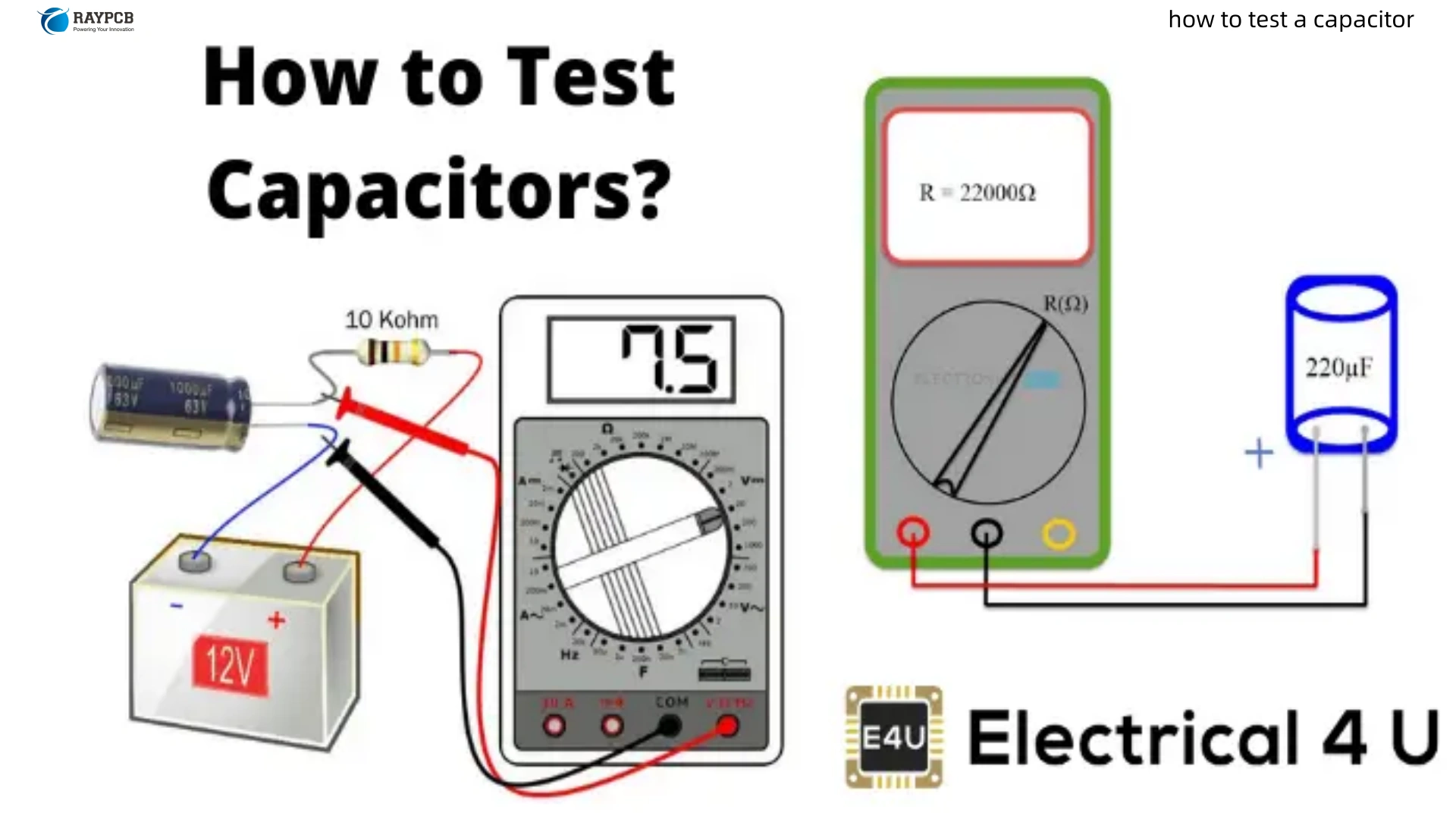
How to Test a Capacitor with a Multimeter
A standard digital multimeter gives you two useful testing modes for capacitors: resistance/continuity mode for a basic sanity check, and capacitance mode for a more quantitative measurement. Neither replaces an ESR meter for electrolytic testing, but together they cover most situations.
H3: Multimeter Resistance Mode Test (Basic Go/No-Go)
This method works on polarized capacitors (electrolytics, tantalums) and gives you a quick pass/fail result. It won’t give you ESR or an accurate capacitance value, but it tells you whether the capacitor is shorted, open, or behaving like a capacitor.
Steps:
- Remove the capacitor from the circuit (in-circuit resistance testing gives false readings due to parallel paths)
- Discharge the capacitor fully
- Set the multimeter to resistance mode — use the highest range (2MΩ or higher) for large caps, mid-range (200kΩ) for small ones
- For a polarized capacitor, connect red probe to the positive lead, black to negative
- Observe the reading
What to expect from a good capacitor:
| Phase | Reading | Explanation |
| Initial | Low resistance (near 0Ω) | Capacitor is charging through the meter’s internal battery |
| Rising | Resistance climbs steadily | Cap is charging — resistance appears to increase |
| Final | High resistance (MΩ range) or OL | Fully charged — no more current flowing |
A good capacitor shows this charging arc. The larger the capacitor, the longer it takes to reach steady state.
Failed capacitor readings:
| Reading | Verdict |
| Stays at 0Ω / near zero permanently | Shorted capacitor — replace immediately |
| OL immediately with no charging arc | Open capacitor — replace |
| Unstable, fluctuating reading | Leaky capacitor — likely failed |
H3: Multimeter Capacitance Mode Test
Most mid-range and higher digital multimeters include a capacitance (F) function. This is more useful than resistance mode because it gives you an actual capacitance value to compare against the component’s rated value.
Steps:
- Discharge the capacitor completely before connecting to the meter
- Remove from circuit — in-circuit measurements are unreliable
- Set meter to capacitance mode (usually marked with a capacitor symbol or “F”)
- Insert leads into the correct meter ports (some meters have dedicated capacitance terminals)
- For polarized caps, observe polarity — red probe to positive lead
- Wait for the reading to stabilize
Acceptable tolerance ranges:
| Capacitor Type | Typical Tolerance | Acceptable Range |
| Aluminum Electrolytic | ±20% | 80%–120% of rated value |
| Tantalum | ±10–20% | 80%–120% of rated value |
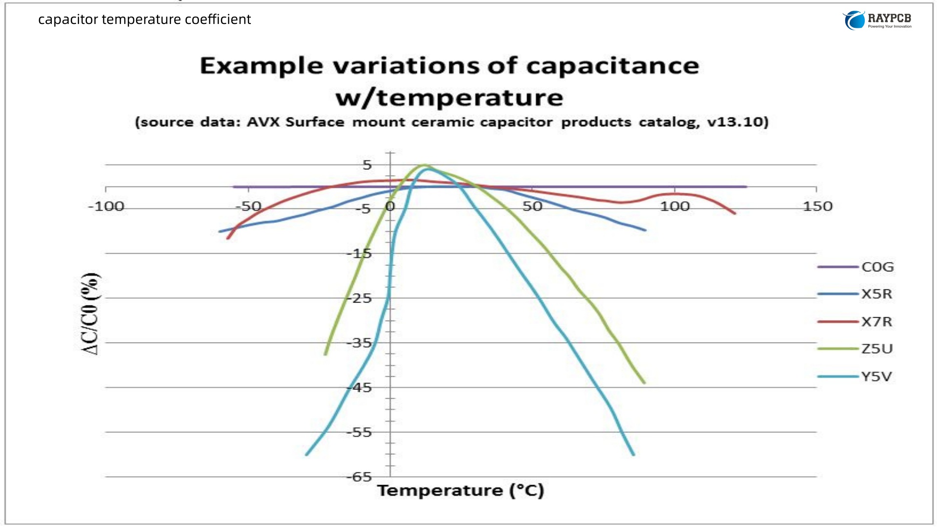
| Ceramic (Class II, X5R/X7R) | ±10–20% | May read lower due to DC bias effect |
| Film | ±1–5% | Very tight — deviation flags a problem |
| Ceramic (Class I, C0G/NP0) | ±1–5% | Stable — close reading expected |
Important caveat on ceramics: High-capacitance ceramic capacitors (X5R, X7R types above 1µF) show significant capacitance reduction under DC bias. A 10µF X5R cap measured out-of-circuit on a bench meter may read 8–9µF and be perfectly fine. In-circuit under operating voltage it may only deliver 4–5µF. This is normal Class II ceramic behavior, not a fault.
H3: Multimeter Diode Mode for Leakage Check
Some engineers use diode mode as an alternative leakage test, particularly for tantalum capacitors. Place the red probe on the positive lead. A good cap shows a brief deflection then returns to OL. Any persistent low reading in diode mode suggests leakage and the capacitor should be replaced.
How to Test a Capacitor with an ESR Meter
This is where serious capacitor diagnostics begins. For electrolytic and tantalum capacitors used in switch-mode power supplies, voltage regulators, and audio circuits, ESR (Equivalent Series Resistance) is the critical parameter — not just capacitance.
H3: What Is ESR and Why Does It Matter?
ESR is the resistive component in series with the ideal capacitance inside a real capacitor. It comes from the resistance of the leads, the foil plates, and critically — the electrolyte itself. As an electrolytic capacitor ages and its electrolyte dries out, ESR rises. A capacitor with doubled ESR is borderline. A cap with 10× its rated ESR is functionally useless in most power supply applications, even if it still shows near-correct capacitance.
High ESR causes:
- Ripple voltage increase on power rails
- Heat buildup inside the capacitor under ripple current
- Voltage regulator instability and oscillation
- Audio distortion in amplifier stages
| ESR Condition | Effect on Circuit |
| Normal (manufacturer spec) | Correct filtering, stable regulation |
| 2–5× spec ESR | Increased ripple, marginal performance |
| 10×+ spec ESR | Circuit malfunction, excess heat |
| Open internal connection | Complete loss of capacitance |
H3: In-Circuit ESR Testing
The major advantage of a dedicated ESR meter is that many designs allow in-circuit testing without desoldering the component. ESR meters inject a low-voltage, high-frequency AC signal (typically 100kHz) that is too small to forward-bias semiconductor junctions in parallel circuit paths, giving a reading that closely represents the capacitor’s ESR alone.
Steps for in-circuit ESR testing:
- Power off and discharge the circuit
- Zero the meter with probes shorted together (lead resistance compensation)
- Touch probes directly to the capacitor leads or pads — polarity doesn’t matter for ESR meters
- Read the ESR value and compare to reference tables
In-circuit results can read slightly higher than true ESR due to parallel resistance paths. If a cap reads borderline high, remove it and test out-of-circuit to confirm.
H3: ESR Reference Values by Capacitance and Voltage
ESR specifications vary by manufacturer, capacitance, voltage rating, and temperature. These are general reference values:
| Capacitance | Voltage Rating | Good ESR | Suspect ESR | Failed ESR |
| 10µF | 16–50V | < 2Ω | 2–10Ω | > 10Ω |
| 100µF | 16–50V | < 1Ω | 1–5Ω | > 5Ω |
| 470µF | 16–50V | < 0.5Ω | 0.5–2Ω | > 2Ω |
| 1000µF | 16–50V | < 0.3Ω | 0.3–1Ω | > 1Ω |
| 3300µF | 10–25V | < 0.15Ω | 0.15–0.5Ω | > 0.5Ω |
Always cross-reference against the specific datasheet. Low-ESR capacitors designed for switching supply applications will have tighter specs than standard electrolytics.
H3: Recommended ESR Meter Options
| Meter | Type | Notes |
| MESR-100 | Dedicated ESR meter | Affordable, in-circuit capable, auto-ranging |
| Atlas ESR70 | Dedicated ESR + capacitance | Excellent accuracy, used by many professionals |
| Peak ESR60+ | Compact ESR meter | Fast, reliable, good for field work |
| LCR-T4 / LCR-T7 | Component tester | Measures ESR, capacitance, and identifies component type |
| Fluke 87V | Premium DMM | Capacitance only — no ESR function |
How to Test a Capacitor In-Circuit vs. Out-of-Circuit
This question comes up constantly and the answer depends on what you’re testing for.
| Test Type | In-Circuit | Out-of-Circuit |
| Visual inspection | ✅ Yes | ✅ Yes |
| Resistance / charging test | ❌ Not reliable | ✅ Best method |
| Capacitance measurement | ❌ Parallel paths cause errors | ✅ Accurate |
| ESR meter test | ✅ Usually acceptable | ✅ Most accurate |
| Leakage test | ❌ Not reliable | ✅ Yes |
The general rule: for a definitive pass/fail, desolder and test out-of-circuit. For a fast screening pass during board-level fault isolation, an ESR meter in-circuit is your best tool.
Testing Ceramic Capacitors (MLCCs)
Ceramic capacitors fail differently from electrolytics. They don’t bulge or vent — they crack. A cracked MLCC typically presents as an intermittent short or leakage path that appears only under mechanical stress or thermal cycling.
Testing MLCCs:
- Resistance mode: a good ceramic should read OL immediately. Any finite resistance reading in the MΩ range or lower indicates leakage or cracking.
- Capacitance mode: useful for confirming value in out-of-circuit testing
- Flexure test: gently flex the PCB near the suspect component while monitoring with a multimeter in resistance mode — an intermittent crack will show up as a momentary resistance drop
Capacitors in high-stress locations on a PCB — near board edges, near large connectors, or in areas subject to thermal cycling — are prime candidates for flexure-induced cracking.
Testing Film and Mica Capacitors
Film and mica capacitors are the most reliable capacitor types in common use. They rarely fail unless subjected to overvoltage or physical damage. Testing is straightforward:
- Resistance mode: Should read OL immediately with no charging arc (values too small to show charging on most meters)
- Capacitance mode: Should read within 1–5% of rated value for quality film caps
- Diode/continuity mode: Any beep or low resistance reading indicates a failed cap
Common Capacitor Test Mistakes to Avoid
Not discharging before testing. Beyond the safety risk, a charged cap will give a false high reading on capacitance mode and damage your meter if the voltage is high enough.
Testing electrolytics in-circuit with a standard DMM. Parallel circuit paths around the capacitor corrupt the reading. What looks like a 100µF cap might be the parallel combination of your cap and a 120Ω resistor.
Judging electrolytics by capacitance alone. A cap at 95% of rated capacitance with 8× its rated ESR will cause the same power supply instability as a completely open cap in many circuits.
Missing ceramic cracks. Ceramics look fine visually when cracked. Add a flexure check to your process when chasing intermittent faults on dense SMD boards.
Trusting a single OL reading on a large cap. A very large capacitor (thousands of µF) takes time to charge through a multimeter’s internal source. Give it several seconds before concluding it’s open.
Useful Resources for Capacitor Testing
- Nichicon Capacitor Application Guide — nichicon.co.jp — Life expectancy, ESR data, and derating guidelines for aluminum electrolytics
- KEMET Capacitor Finder & Datasheets — kemet.com — Parametric search including ESR specs for tantalum and ceramic types
- Murata SimSurfing Design Tool — product.murata.com — Simulate MLCC capacitance vs. DC bias and temperature
- Capacitor ESR Reference Chart (EEVblog) — Community-maintained ESR reference values for common electrolytic series
- Digi-Key Capacitor Parametric Search — digikey.com — Filter by ESR, capacitance, voltage, and temperature rating
- IPC-A-610 Acceptability of Electronic Assemblies — Industry standard covering inspection criteria including capacitor installation
- Atlas ESR70 Component Database — Included with Atlas ESR meter — manufacturer ESR specs for thousands of capacitor part numbers
FAQs: How to Test a Capacitor
Q1: Can I test a capacitor without removing it from the board? For ESR testing, yes — a dedicated ESR meter works reliably in-circuit on most boards. For capacitance testing, in-circuit measurement is unreliable due to parallel component paths. For a definitive capacitance reading, desolder and test out-of-circuit. Visual inspection is always done in-circuit first.
Q2: My multimeter shows the correct capacitance but the circuit still doesn’t work — why? Almost certainly ESR. A capacitor can retain near-nominal capacitance while its ESR has climbed to unusable levels. This is the most common scenario in aging switch-mode power supplies. Get an ESR meter and check the actual series resistance before replacing other components.
Q3: How do I test an SMD capacitor that’s already on the board? For SMD electrolytics: an ESR meter with fine-tipped probes touches directly to the solder pads. For MLCCs: use resistance mode (should read OL) or capacitance mode out-of-circuit after hot-air removal. For in-circuit MLCC crack detection, the board flexure method while monitoring resistance is the most effective approach.
Q4: What’s the difference between testing a tantalum vs. an aluminum electrolytic capacitor? The testing methods are identical but the failure modes differ. Tantalums fail more often as shorts (catastrophic, sometimes with fire) where electrolytics tend to fail as opens or high-ESR degradation. A tantalum reading near-zero resistance in any mode should be treated as a serious fault — tantalum shorts can cause PCB trace damage. Also note: tantalum stripe marking indicates positive (opposite to electrolytic convention).
Q5: How do I know if my multimeter is accurate enough to test capacitors? For a basic go/no-go test (shorted or open), any functional DMM works. For capacitance measurement within ±5% accuracy, you need a meter with a specified capacitance accuracy — most mid-range meters (Uni-T UT61, Fluke 115 and above, Brymen 867) are adequate. For ESR measurement, you need a dedicated ESR meter or LCR meter — a standard DMM cannot measure ESR regardless of price.
Wrapping Up
Knowing how to test a capacitor is less about memorizing steps and more about understanding what each test actually tells you. Visual inspection first, resistance mode for a quick sanity check, capacitance measurement for value verification, and ESR testing for the failure mode that actually kills circuits in the field. Use the right tool for each question, and don’t stop at capacitance alone when you’re hunting down a failing power supply.
The bench time you spend learning these methods pays back the first time you diagnose a failed switching regulator in fifteen minutes instead of three hours.