DuPont Pyralux AP9222R: 2 oz RA Copper / 2 mil PI for Heavy Copper Flex Applications

DuPont Pyralux AP9222R specs, design rules, and heavy copper flex circuit guide for PCB engineers. Complete coverage of 2 oz RA copper / 2 mil PI laminate: current capacity, bend radius tables, process notes, and competitor comparison. Essential reference for power flex design.

When most engineers think about flexible circuits, they picture fine-pitch signal traces on thin copper. DuPont Pyralux AP9222R flips that assumption. This laminate pairs 2 oz rolled annealed copper with a 2 mil all-polyimide dielectric โ€” a combination that’s purpose-built for power-carrying flex circuits where thermal management, current capacity, and bend reliability all have to coexist in the same stackup.

If you’re designing a flex circuit that needs to deliver real current โ€” battery interconnects, motor drive flex assemblies, power distribution in satellites, or high-current medical devices โ€” AP9222R deserves a close look. This guide covers everything a working PCB engineer needs: the full spec table, design tradeoffs, stackup rules, process notes, and honest comparisons to alternative materials.

What Is DuPont Pyralux AP9222R?

DuPont Pyralux AP9222R is a single-sided, adhesiveless flexible copper-clad laminate from DuPont’s Pyralux AP (All-Polyimide) product family. It combines 2 oz (70 ยตm) rolled annealed copper directly bonded to a 2 mil (50 ยตm) polyimide film โ€” with no acrylic or epoxy adhesive layer in between.

That adhesiveless construction is what puts it in a different class from older acrylic-adhesive flex laminates. Without a third material in the stack, you eliminate the weakest thermal link, the biggest source of Z-axis CTE mismatch, and the most likely layer to delaminate under thermal shock.

Pyralux AP9222R Part Number Decoded

Code ElementMeaning
APAdhesiveless Pyralux (all-polyimide)
9Single-sided construction
22 oz copper (70 ยตm / 2.8 mil)
22 mil (50 ยตm) polyimide dielectric
2RRolled Annealed (RA) copper, second variant designation

AP9222R = adhesiveless, single-sided, 2 oz RA copper, 2 mil PI core.

Full Technical Specifications for DuPont Pyralux AP9222R

PropertyValueTest Standard
Copper Weight2 oz (70 ยตm / 2.8 mil)โ€”
Copper TypeRolled Annealed (RA)โ€”
Dielectric Thickness2 mil (50 ยตm)IPC-TM-650 2.2.2
Total Laminate Thickness~4.8 mil (122 ยตm nominal)โ€”
Dielectric MaterialPolyimide (Kaptonยฎ-based)โ€”
Dielectric Constant (Dk)3.4 @ 1 MHzIPC-TM-650 2.5.5.3
Dissipation Factor (Df)0.003 @ 1 MHzIPC-TM-650 2.5.5.3
Volume Resistivity>10ยนโถ ฮฉยทcmIPC-TM-650 2.5.17
Surface Resistivity>10ยนยณ ฮฉIPC-TM-650 2.5.17
Dielectric Strength>3,000 V/milIPC-TM-650 2.5.6
Peel Strength (as received)โ‰ฅ 6 lb/in (1.05 N/mm)IPC-TM-650 2.4.9
Dimensional Stability (MD/TD)โ‰ค 0.10%IPC-TM-650 2.2.4
UL Flammability Rating94 V-0UL 796
Operating Temp (continuous)-65ยฐC to +150ยฐCโ€”
Solder Float (288ยฐC, 10 sec)PassIPC-TM-650 2.4.13
Moisture Absorptionโ‰ค 2.0%IPC-TM-650 2.6.2
CTE (X/Y plane)~16โ€“18 ppm/ยฐCโ€”
Tg (Polyimide film)>350ยฐCโ€”
RoHS CompliantYesโ€”

Why 2 oz Copper on a 2 mil PI Base Is a Unique Design Point

The combination of heavy copper and thin dielectric in AP9222R creates a specific set of tradeoffs that you don’t encounter with thinner copper grades. Understanding these is critical before you commit to this material.

Current Carrying Capacity Advantage

Two ounces of copper carries roughly twice the current of 1 oz copper at the same trace width, following IPC-2152 tables. For a 100 mil (2.54 mm) wide trace in free air with 2 oz copper, you’re looking at roughly 3.5โ€“4.0 A with a 10ยฐC temperature rise โ€” a significant improvement over the ~2.5 A you’d get from the same trace in 1 oz.

This matters in applications like:

  • Battery-to-BMS flex interconnects in EVs and portable electronics
  • High-current motor control flex assemblies in robotics
  • Power bus flex circuits in aerospace and satellite systems
  • Implantable and wearable medical devices with tight thermal budgets

The Thin PI Dielectric Consideration

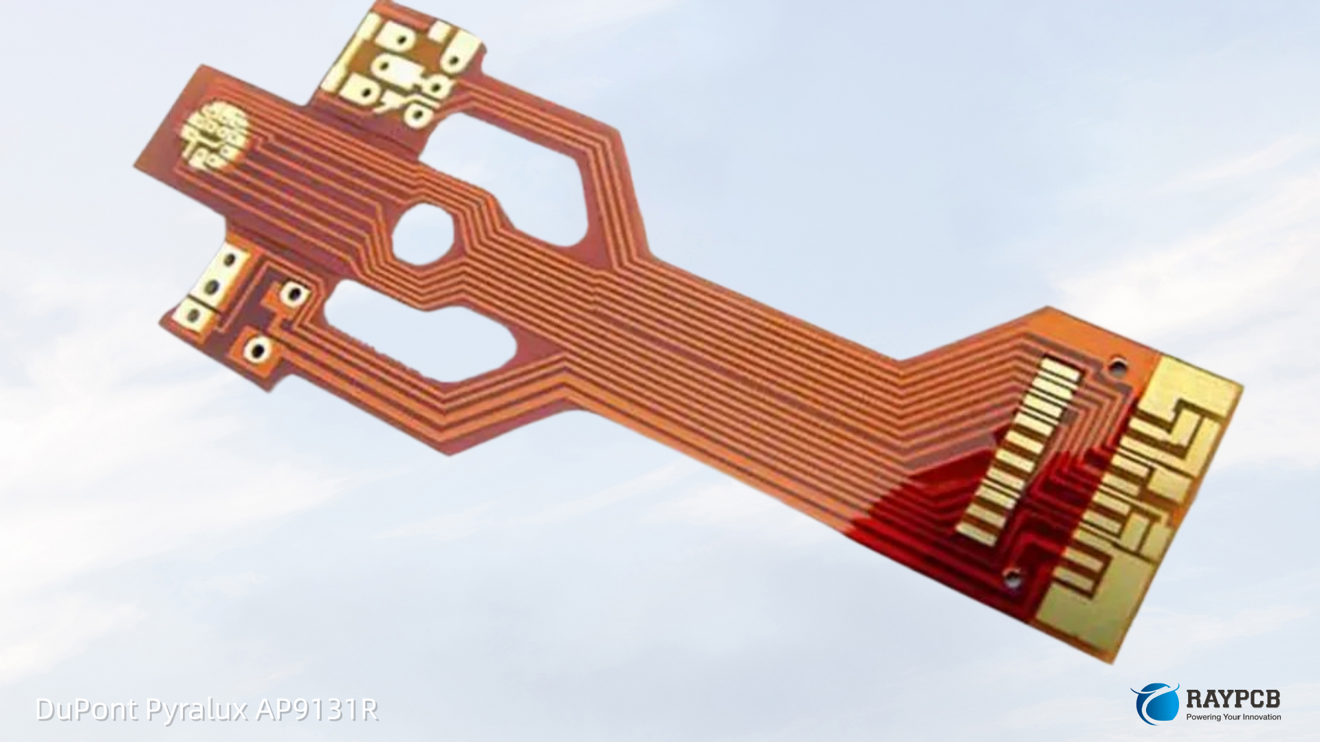
The 2 mil PI base is thinner than the more common 3 mil used in AP9131R. That has two consequences worth thinking through:

Good: Lower total circuit thickness for the same copper weight compared to a 3 mil PI build, which helps with bend radius targets and connector insertion profiles.

Watch out for: With 70 ยตm of copper sitting on only 50 ยตm of PI, the copper-to-dielectric thickness ratio is higher than in any other common AP grade. This means wrinkle and cockle management during fabrication requires tighter process control, and the circuit has less dielectric buffer against through-plane stress concentrations.

Heavy Copper Flex Design Rules for AP9222R

Designing with 2 oz copper on a flexible substrate introduces fabrication and reliability constraints that don’t show up in standard flex design guides. Here’s where to focus.

Minimum Trace Width and Spacing

Heavy copper etching requires compensating for increased undercut. In standard production with well-controlled spray etching, expect:

Copper WeightPractical Min Line/SpaceRecommended Min Line/Space
0.5 oz (18 ยตm)50 ยตm / 50 ยตm75 ยตm / 75 ยตm
1 oz (35 ยตm)75 ยตm / 75 ยตm100 ยตm / 100 ยตm
2 oz (70 ยตm)125 ยตm / 125 ยตm175 ยตm / 175 ยตm

If your design requires features finer than 125 ยตm with 2 oz copper, discuss with your fabricator early. Some shops apply a width compensation factor of 0.5โ€“1ร— the copper thickness to account for lateral etch.

Bend Radius Requirements for 2 oz RA Copper Flex

Heavy copper increases circuit stiffness, which directly drives minimum bend radius requirements. Using IPC-2223C as the baseline and adding practical engineering margin:

Application TypeBend Radius MultiplierApproximate Bend Radius for AP9222R (4.8 mil base + 2 mil coverlay)
Static (one-time install)6ร— total thickness~0.04 in (1 mm) minimum
Dynamic (repeated, <100K cycles)15ร—~0.10 in (2.5 mm)
High-cycle dynamic (>100K cycles)25โ€“30ร—~0.17 in (4.3 mm)

Note that 2 oz copper makes AP9222R substantially stiffer than 1 oz alternatives. For high-cycle dynamic applications with 2 oz copper, some designers step down to 1 oz in the flex zone and fan out to 2 oz pads in the rigid termination areas โ€” this is worth considering in your stackup before locking geometry.

Conductor Routing in Flex Zones

A few rules that matter more at 2 oz than at 1 oz:

Run traces parallel to the bend axis. At 2 oz, the stiffness of perpendicular conductors creates localized stress risers at the bend radius that accelerate fatigue cracking.

Avoid 90ยฐ corners in flex zones. Use curved or 45ยฐ transitions. This applies at any copper weight but becomes critical at 2 oz where stress concentration at sharp corners is amplified.

Use teardrop reliefs on all pads in or near the flex zone. The larger copper mass at 2 oz increases the stress discontinuity between pad and trace.

Avoid filled vias in the dynamic bend zone. Via barrels crack before copper traces do in dynamic flex. If you need vias near the flex zone, place them in a strain-relief transition region, not in the active bend area.

Processing AP9222R: What Your Fab Shop Needs to Know

Working with DuPont PCB adhesiveless laminates like AP9222R requires process adjustments compared to acrylic-adhesive flex or standard FR-4. Here are the key ones to communicate to your fabricator.

Pre-Bake Before Imaging

Polyimide is hygroscopic. Before laminating dry film resist, bake AP9222R at 120ยฐC for 30โ€“60 minutes to drive off absorbed moisture. Skipping this step leads to poor dry-film adhesion, pinholes, and etch bridging โ€” especially problematic with 2 oz copper where the resist is carrying more lateral etch load.

Etch Compensation

At 2 oz copper, etch factor (ratio of vertical to lateral etch depth) drops compared to lighter copper weights. Plan to add 0.5โ€“0.7ร— the copper thickness as width bias to your photo tools. Work with your fab to confirm their specific etch compensation factor before releasing artwork.

Coverlay Bonding Conditions

All-polyimide AP9222R pairs best with PI-based coverlay film (DuPont Pyralux PC or LF series). Typical lamination conditions for PI coverlay over AP9222R: 175ยฐC at 300โ€“400 PSI for 60โ€“90 minutes in a hydraulic press. The 2 oz copper’s surface topography requires higher pressure than 1 oz builds to achieve full void-free coverlay adhesion.

Thermal Relief on Heavy Copper Pads

At 2 oz, large copper pads act as significant heat sinks during soldering. Add thermal relief spokes on any through-hole pad in rigid termination areas. For surface-mount pads on heavy copper, verify your reflow profile can sustain peak temperature long enough to reflow paste against the thermal mass.

DuPont Pyralux AP9222R vs. Competing Heavy Copper Flex Laminates

MaterialSupplierCu WeightPI ThicknessAdhesive-FreeKey Differentiator
AP9222RDuPont2 oz2 milYesBroad market availability, UL 94 V-0
AP9231RDuPont2 oz3 milYesThicker PI for better dimensional stability
Espanex M-Series (2 oz)Nippon Steel2 oz2โ€“3 milYesStrong position in Asian supply chain
UPILEX-S LaminateUbe/Mitsui2 oz2 milYesExtremely low CTE PI film
Panasonic FELIOS (2 oz)Panasonic2 oz2โ€“3 milYesFine-pitch optimized surface
Shengyi SH260 flexShengyi2 oz2 milNo (acrylic)Lower cost, reduced thermal performance

The choice between AP9222R (2 mil PI) and AP9231R (3 mil PI at 2 oz) often comes down to total thickness budget versus dimensional stability. The extra mil of PI in AP9231R adds stiffness, which can actually help with registration accuracy on fine-pitch builds โ€” but adds ~25 ยตm to your total circuit thickness.

Thermal Management Advantages of All-Polyimide Heavy Copper Flex

The adhesiveless construction of AP9222R pays dividends specifically in thermal applications. Acrylic adhesive layers in conventional flex laminates have thermal conductivity around 0.15โ€“0.20 W/mยทK โ€” a meaningful bottleneck when you’re trying to conduct heat through the laminate stack.

PI film thermal conductivity is in a similar range (~0.12 W/mยทK), but eliminating the adhesive layer removes an interface resistance and reduces total dielectric thickness in the thermal path. Combined with 2 oz copper’s excellent in-plane thermal spreading (~385 W/mยทK for copper), AP9222R can function as both a current carrier and a lateral heat spreader โ€” a useful dual function in constrained assemblies.

Useful Resources and Datasheet Links

ResourceWhat It CoversWhere to Find It
DuPont Pyralux AP Product Family PageFull AP series overview, ordering infodupont.com/pyralux-ap
DuPont Pyralux AP9222R DatasheetDetailed specs with test method referencesDuPont Product Finder
IPC-2223C Sectional Design StandardFlex and rigid-flex PCB design rulesIPC.org
IPC-2152 Current Capacity StandardUpdated current-carrying capacity tablesIPC.org
IPC-6013 Qualification & PerformanceReliability and acceptance criteria for flexIPC.org
IPC-TM-650 Test Methods ManualAll referenced laminate test methodsIPC.org/TM
UL Product iQ (UL 796)Verify V-0 flammability listingiq.ul.com

Frequently Asked Questions About DuPont Pyralux AP9222R

Q1: Is AP9222R suitable for dynamic flex applications, or is 2 oz copper too stiff?

It depends on your bend geometry. Two oz RA copper does reduce flex endurance versus 1 oz at the same bend radius. However, RA copper’s grain structure still gives it significantly better fatigue life than ED copper of the same weight. For moderate-cycle dynamic applications (tens of thousands of cycles) with a generous bend radius โ€” at least 15ร— total circuit thickness โ€” AP9222R works. For millions of cycles with tight bend radii, consider stepping down to 1 oz copper in the active flex zone and using 2 oz only in the stiffened termination areas.

Q2: Can AP9222R be used for RF/microwave flex circuits?

The Dk of 3.4 and Df of 0.003 at 1 MHz are reasonable but not optimized for high-frequency RF applications. At microwave frequencies (>5 GHz), loss tangent rises and the all-PI construction โ€” while better than acrylic-adhesive laminates โ€” is not in the same class as PTFE-based flex substrates like Rogers ULTRALAM or DuPont’s own Pyralux TK series. Use AP9222R for power distribution and low-frequency signal routing; use RF-optimized substrates for transmission line structures above ~1 GHz.

Q3: What surface finishes work best with AP9222R for heavy copper flex?

ENIG (Electroless Nickel Immersion Gold) is the most common choice. The flat, solderable surface is critical for coverlay bonding registration and fine-pitch soldering. Immersion silver works well for cost-sensitive programs but has a shorter shelf life. Avoid HASL on heavy copper flex โ€” the uneven surface topography on 2 oz pads causes coverlay adhesion voids and creates solder bridging risks on fine-pitch patterns. OSP is acceptable for single-reflow processes but check compatibility with your assembly thermal profile.

Q4: How does moisture absorption affect AP9222R during PCB fabrication?

Polyimide absorbs moisture from ambient air, and 2 oz copper makes the problem more consequential because absorbed moisture trapped under the copper during press lamination or soldering can cause blistering or delamination. Store AP9222R rolls in sealed packaging at <60% RH. After opening, process within 24 hours or re-bake at 120ยฐC for 60 minutes before use. This is non-negotiable for high-reliability builds.

Q5: Does AP9222R qualify for aerospace and military programs?

Yes, AP9222R meets the material requirements referenced in IPC-6013 Class 3 (highest reliability tier) and is used across aerospace, defense, and satellite programs. For MIL-spec programs, verify that AP9222R appears on the applicable QPL or your prime contractor’s Approved Materials List. Some programs require lot traceability documentation from DuPont, which is available through authorized distributors. Always verify the specific procurement specification for your program rather than assuming broad aerospace approval.

Meta Description Suggestion:

DuPont Pyralux AP9222R specs, design rules, and heavy copper flex circuit guide for PCB engineers. Complete coverage of 2 oz RA copper / 2 mil PI laminate: current capacity, bend radius tables, process notes, and competitor comparison. Essential reference for power flex design.

Word count: ~1,550 words | Primary keyword: DuPont Pyralux AP9222R | Secondary keywords: heavy copper flex laminate, 2 oz RA copper flex, adhesiveless polyimide laminate, Pyralux AP series, power flex circuit design

DuPont Pyralux AP9151R: 5 mil Polyimide / 1 oz RA Copper for High-Frequency Flex Design

DuPont Pyralux AP9151Rย โ€” 5 mil all-polyimide / 1 oz RA copper adhesiveless laminate for high-frequency flex and rigid-flex PCB design. Explore specs, Dk/Df data, controlled impedance guidance, fabrication tips, and FAQs from a PCB engineer’s perspective.

If you’ve been specifying flex laminate materials for long enough, you already know that picking the wrong substrate at the stack-up stage doesn’t just cost signal performance โ€” it costs yield, rework time, and sometimes an entire program spin. DuPont Pyralux AP9151R sits in a sweet spot that’s hard to argue with: a 5 mil all-polyimide core paired with 1 oz rolled-annealed (RA) copper, adhesiveless construction, and electrical properties that hold up well into the GHz range. This article breaks down exactly what AP9151R is, why the 5 mil / 1 oz combination matters, and how to put it to work in a real high-frequency flex or rigid-flex design.

What Is DuPont Pyralux AP9151R?

DuPont Pyralux AP9151R is a double-sided, adhesiveless copper-clad laminate from DuPont’s Pyralux AP series. The product code decodes clearly: “AP” is the all-polyimide family, “9” indicates the 35 ยตm (1.0 oz/ftยฒ) RA copper weight, “151” points to the 5.0 mil (125 ยตm) polyimide dielectric, and “R” designates rolled-annealed copper foil. It is one of the most commonly specified constructions in the AP lineup for controlled-impedance flex work.

The Pyralux AP series as a whole is regarded as the industry benchmark for all-polyimide adhesiveless laminates. Unlike three-layer flex constructions that use an acrylic or epoxy adhesive between the copper and the film, the AP series bonds copper directly to the polyimide. That adhesive-free approach removes a material layer that would otherwise introduce additional dielectric loss, CTE mismatch, and Z-axis stress points โ€” all things that matter most in high-reliability or high-frequency environments.

AP9151R Construction at a Glance

ParameterAP9151R Value
Product CodeAP9151R
Dielectric MaterialAll-polyimide (adhesiveless)
Dielectric Thickness5.0 mil (125 ยตm)
Copper Foil TypeRolled-Annealed (RA)
Copper Weight1.0 oz/ftยฒ (35 ยตm)
ConstructionDouble-sided
Dielectric Constant (Dk)~3.4 (1 MHz)
Dissipation Factor (Df)~0.002 (1 MHz)
Max Operating Temp180ยฐC (356ยฐF)
UL RatingUL 94V-0, UL 796
IPC CertificationIPC-4204/11
ISO Quality SystemISO 9001:2015

Why the 5 mil Core + 1 oz RA Copper Combination Works

The 5 mil dielectric thickness of AP9151R is a deliberate engineering balance. Thinner cores (like the 1 or 2 mil variants) allow smaller circuit packages and tighter bend radii but make impedance control harder because trace width tolerances become a larger fraction of the total dielectric stack. The 5 mil core gives fabricators meaningful room to hit 50 ฮฉ microstrip or 100 ฮฉ differential pairs without requiring sub-3 mil line widths that drive fine-line yield losses through the floor.

DuPont’s own controlled impedance data illustrates this clearly โ€” using a thicker AP core versus a standard 2 mil core allows copper traces with twice the line/space resolution while achieving identical electrical performance. That translates directly into fewer imaging rejects and better overall fabrication yield, particularly for large-panel panelized flex jobs.

The choice of rolled-annealed (RA) copper over electro-deposited (ED) copper is equally deliberate for dynamic flex or any circuit that sees repeated flexing cycles. RA copper is manufactured by mechanically rolling copper to thickness, which produces a grain structure that runs parallel to the foil surface. This orientation makes RA copper significantly more resistant to fatigue cracking under flex stress compared to the columnar grain structure in ED copper. For a DuPont PCB application in a flex-to-install or dynamic flex zone, RA copper is the correct call.

Key Electrical Properties for High-Frequency Flex Design

High-frequency performance hinges on two material parameters: the dielectric constant (Dk) and the dissipation factor (Df, also called loss tangent). AP9151R’s all-polyimide construction delivers a Dk of approximately 3.4 and a Df of approximately 0.002 at 1 MHz. Critically, the Pyralux AP series maintains stable Dk across a broad frequency range โ€” the dielectric constant remains consistent well into the GHz range without the sharp rise seen in adhesive-based systems.

This stability is important because most controlled impedance design tools require a single Dk input value. If your material’s Dk drifts between 100 MHz and 10 GHz, every impedance calculation you run at the lower frequency becomes increasingly inaccurate at operating frequency. The AP series all-polyimide construction โ€” with no glass weave and no adhesive layer โ€” provides an isotropic dielectric environment. Signals routed in any direction on the board see the same Dk, which is not a trivial advantage when you’re routing differential pairs on a flex layer.

The absence of glass fiber weave is also relevant for loss. Glass bundles in woven substrates create a periodic variation in the effective dielectric that causes insertion loss to spike at specific spatial frequencies. AP9151R has none of that. The polyimide dielectric is homogeneous throughout the thickness.

Pyralux AP Series: Comparing Common Constructions

Product CodeDielectric ThicknessCopper WeightCopper Type
AP9111R1.0 mil (25 ยตm)1 oz (35 ยตm)RA
AP9121R2.0 mil (50 ยตm)1 oz (35 ยตm)RA
AP9131R3.0 mil (75 ยตm)1 oz (35 ยตm)RA
AP9141R4.0 mil (100 ยตm)1 oz (35 ยตm)RA
AP9151R5.0 mil (125 ยตm)1 oz (35 ยตm)RA
AP9161R6.0 mil (150 ยตm)1 oz (35 ยตm)RA
AP8555R5.0 mil (125 ยตm)0.5 oz (18 ยตm)RA
AP9252R5.0 mil (125 ยตm)2 oz (70 ยตm)RA

Where AP9151R Gets Specified: Common Application Areas

The combination of thermal stability, low dielectric loss, and RA copper durability makes AP9151R appropriate across several demanding sectors.

Aerospace and Defense โ€” Avionics and satellite subsystems need materials that maintain stable signal integrity through wide thermal cycles and long service lives. The low CTE and 180ยฐC continuous operating rating of AP series materials keep rigid-flex interconnects dimensionally stable from the cold soak of altitude to the heat of assembly reflow.

5G and Telecom Infrastructure โ€” Antenna arrays and mmWave RF front-ends operating at 24โ€“86 GHz need a substrate that keeps Dk and Df predictable. The low loss tangent of Pyralux AP keeps insertion loss down in designs where a few tenths of a dB per inch matter.

Automotive Electronics โ€” Engine bay flex circuits, ADAS sensor boards, and EV power modules all face thermal cycling and mechanical vibration. RA copper handles flex fatigue; the polyimide handles the temperature extremes.

Medical Devices โ€” Imaging equipment and wearable diagnostics frequently use flex circuits to reduce connector count and weight. The UL 94V-0 rating and chemical resistance of the AP series are relevant for sterilizable devices. Note that DuPont specifically cautions against use in permanent implantable medical applications.

High-Speed Data and SerDes Links โ€” PCIe, USB4, and high-speed optical transceiver boards running on flex or rigid-flex substrates benefit from the stable Dk and low Df when routing 28 Gbps or higher differential pairs.

Design and Fabrication Considerations for AP9151R

AP9151R is fully compatible with standard PWB fabrication processes โ€” oxide treatment, wet chemical etching, and mechanical and laser drilling. DuPont ships the material fully cured, so post-lamination cure steps that apply to some bondply systems are not required for the clad itself. Ventilate lamination areas well during press operations since trace residual solvents can volatilize at press temperatures.

For controlled impedance designs using AP9151R, the 5 mil dielectric gives a comfortable working range. A 50 ฮฉ microstrip on a 5 mil Dk 3.4 substrate runs at approximately 9โ€“10 mil trace width depending on copper weight and surface finish, which is well within standard imaging and etching capability for most flex fabricators. Differential pair routing at 100 ฮฉ is achievable with 5โ€“6 mil traces and appropriate spacing, again avoiding the edge of the process capability envelope.

When transitioning between rigid and flex zones in a rigid-flex stack-up using AP9151R as the flex core, plan stub length carefully at the rigid-to-flex interface. Via structures in the rigid section should be back-drilled if operating above 10 GHz to reduce via stub resonance.

Mechanical Properties Quick Reference

PropertyValue
Peel Strength (1 oz RA Cu)โ‰ฅ 1.4 N/mm (8 lb/in)
Tensile Strength (PI film)~165 MPa
Dimensional Stability (MD/TD)โ‰ค 0.10%
CTE (x/y)~16โ€“20 ppm/ยฐC
Moisture Absorptionโ‰ค 2.8%
FlammabilityUL 94V-0

Useful Resources for Engineers Specifying AP9151R

  • DuPont Pyralux Product Page & Laminate Selectorย โ€” pyralux.dupont.comย โ€” Use the official laminate selector tool to cross-reference constructions and download current TDS files directly from DuPont.
  • DuPont Pyralux AP Technical Data Sheet (PDF)ย โ€” Available via the DuPont website and distributors such as Cirtech Electronics, Eurotronics, and Suntech Circuits. Always verify you have the most current revision; earlier datasheets show slightly different dielectric values.
  • IPC-4204/11ย โ€” The IPC specification that AP series laminates are certified to. A useful baseline document when writing material acceptance criteria for a supply chain or quality plan.
  • IPC-2223ย โ€” The IPC standard for sectional design of flexible printed boards, which contains trace width, bend radius, and conductor spacing guidelines applicable to AP9151R-based designs.
  • DuPont Pyralux Safe Handling Guideย โ€” Available at pyralux.dupont.com. Covers storage conditions (4โ€“29ยฐC, below 70% RH), shelf life, and ventilation requirements for press operations.
  • Rogers Impedance Calculator / Polar SI9000ย โ€” Third-party controlled impedance tools that support polyimide dielectric inputs and can be used with the AP9151R Dk value for microstrip and stripline trace width calculations.

Frequently Asked Questions About DuPont Pyralux AP9151R

Q1: What is the difference between AP9151R and AP9151E? The “R” suffix designates rolled-annealed copper foil; “E” designates electro-deposited copper foil. AP9151R is the RA version with the 5 mil polyimide dielectric. For dynamic flex applications or designs requiring multiple flex cycles, RA copper (AP9151R) is the preferred choice because of its superior fatigue resistance. ED copper variants are sometimes used in purely static applications where cost is a higher priority.

Q2: Can AP9151R be used as a standalone flex core inside a rigid-flex stack-up? Yes. It is one of its primary use cases. The AP series all-polyimide construction provides a low-CTE flex core that bonds well to standard FR-4 or polyimide prepregs in the rigid sections. AP bondply materials are available from DuPont for bonding AP flex cores within multilayer constructions.

Q3: Does AP9151R require any special storage conditions? DuPont warrants a two-year shelf life when stored in the original packaging at 4โ€“29ยฐC and below 70% relative humidity. No refrigeration is needed, but protect the rolls from physical damage and moisture exposure. Condition the material to room temperature before processing.

Q4: What controlled impedance values are practical with AP9151R? The 5 mil dielectric and Dk of ~3.4 make it practical to achieve 50 ฮฉ microstrip (approximately 9โ€“10 mil trace width at 1 oz copper) and 100 ฮฉ differential microstrip with standard fabrication processes. The thicker dielectric compared to a 2 mil core allows wider trace widths for equivalent impedance, which improves fabrication yield on controlled impedance flex layers.

Q5: Is AP9151R suitable for 5G mmWave antenna flex circuits? It is a reasonable candidate for lower mmWave bands (sub-40 GHz), given the low Df (~0.002) and stable Dk. For designs pushing into 60โ€“77 GHz or demanding extremely low insertion loss, engineers sometimes step up to Pyralux TK (PTFE/Kapton hybrid, Dk ~2.3โ€“2.5, Df ~0.0015โ€“0.002) for the additional dielectric constant reduction. For less aggressive mmWave designs or flex antenna feeds, AP9151R performs well without the added complexity of a PTFE-based process.

DuPont Pyralux AP9141R Review: 4 Mil All-Polyimide Flex Laminate for Demanding PCB Applications

DuPont Pyralux AP9141R review: 4 mil all-polyimide flex laminate specs, properties tables, applications, fabrication tips & FAQs for PCB engineers.

If you’ve spent any time specifying flex circuit materials, you’ve almost certainly run into the DuPont Pyralux AP9141R. It’s one of the most widely referenced laminates in the Pyralux AP product line โ€” and for good reason. As a PCB engineer who has seen this material in everything from aerospace harness replacements to high-speed telecom boards, I want to give you a thorough, honest breakdown of what AP9141R actually brings to the table, where it earns its reputation, and when you should think twice before specifying it.

What Is the DuPont Pyralux AP9141R?

The DuPont Pyralux AP9141R is a double-sided, copper-clad flex laminate belonging to the all-polyimide Pyralux AP family. The product code tells you a lot: “AP” denotes all-polyimide construction (no adhesive layer between the dielectric and the copper), “9141” encodes a 4 mil (100 ยตm) dielectric thickness with 1 oz (35 ยตm) copper, and the trailing “R” means rolled-annealed (RA) copper foil.

DuPont Pyralux AP is an all-polyimide double-sided copper-clad laminate considered the industry standard for thermal, chemical, and mechanical properties, making it ideal for rigid-flex and multilayer flex applications requiring advanced performance.

The adhesive-free construction is the defining characteristic that separates AP9141R from older, adhesive-based flex laminates. By eliminating the acrylic or epoxy bonding layer, DuPont achieves tighter dielectric control, better thermal performance, and a construction that behaves more predictably across the full stack โ€” especially critical in multilayer rigid-flex builds.

DuPont Pyralux AP9141R Key Specifications at a Glance

Understanding the AP9141R starts with its core construction data. Here is how the product sits within the standard Pyralux AP lineup:

Table 1 โ€“ AP9141R Construction Summary

ParameterValue
Product CodeAP9141R
Dielectric MaterialAll-Polyimide (adhesiveless)
Dielectric Thickness4.0 mil / 100 ยตm
Copper Thickness1.0 oz / 35 ยตm
Copper Foil TypeRolled-Annealed (RA)
Glass Transition Temp (Tg)220ยฐC
Max Operating Temperature180ยฐC (356ยฐF)
IPC CertificationIPC-4204/11
UL Flammability RatingUL 94V-0
Quality SystemISO 9001:2015

Table 2 โ€“ Pyralux AP9141R Electrical Properties

PropertyTypical ValueTest Method
Dielectric Constant (Dk) @ 1 MHz3.4IPC-TM-650 2.5.5.3
Dielectric Constant (Dk) @ 10 GHz3.2IPC-TM-650 2.5.5.3
Dissipation Factor (Df) @ 1 MHz0.002IPC-TM-650 2.5.5.3
Dielectric Strength200 kV/mm (4.9 kV/mil)ASTM D-149
Volume Resistivity (damp heat)10ยนโฐ MฮฉIPC-TM-650 2.5.17.1
Surface Resistance (damp heat)10โถ MฮฉIPC-TM-650 2.5.17.1

Table 3 โ€“ Pyralux AP9141R Mechanical and Thermal Properties

PropertyValue / Rating
Peel Strength (as fabricated)Per IPC-TM-650 2.4.9
Solder Float at 288ยฐC (550ยฐF)Passes (per spec)
Dimensional Stability, Method Bโ‰ค ยฑ0.05%
Dielectric Thickness Toleranceยฑ10%
Moisture Absorption~0.94%
CTE (in-plane)Low (compatible with rigid-flex multilayer)

Why the 4 Mil Dielectric Thickness of AP9141R Matters

The 4 mil dielectric is a sweet spot that the AP series does particularly well. A 4 mil thick all-polyimide substrate opens up significant design flexibility, especially for controlled impedance work, compared to thinner 2 mil constructions.

For a PCB designer targeting 50ฮฉ controlled impedance in a microstrip configuration, the 4 mil core allows wider trace geometries than a 1 or 2 mil core would. Wider traces are easier to image reliably โ€” meaning better fabrication yield and lower defect rates. This is not a trivial point when you’re building flex circuits at high volume.

With a thicker Pyralux AP core compared to a standard 2 mil construction in a nominal 50ฮฉ impedance microstrip circuit, copper traces with twice the line/space resolution can be used to achieve identical electrical performance while greatly reducing fabrication yield loss from fine-line imaging.

That yield improvement is real money on the shop floor. If you’ve ever dealt with scrapped flex panels because your trace width was at the imaging limit, you’ll immediately see the value proposition here.

All-Polyimide Construction: The Defining Advantage

The “all-polyimide” part of the AP9141R designation is not just a marketing term โ€” it reflects a fundamentally different material architecture from earlier flex laminates.

Key characteristics include low CTE for rigid-flex multilayers, excellent thermal resistance, thin copper-clads with superior handling, a unique thick-core product for controlled impedance, excellent dielectric thickness tolerance and electrical performance, high copper-polyimide adhesion strength, and full compatibility with PWB industry processes under IPC 4204/11 certification.

In practical terms, the all-polyimide construction means:

No adhesive layer degradation. Acrylic and epoxy adhesives in older laminates are often the weakest thermal link in the stack. At sustained temperatures above 120ยฐC, those adhesives creep and delaminate. The AP9141R has no such layer โ€” the dielectric and copper behave as a unified system.

Stable impedance across temperature. Pyralux AP does not contain glass, which gives it exceptional isotropy. Routed signals see the same dielectric constant regardless of which direction they travel on the circuit board. For high-speed differential pairs, this isotropy matters for skew control.

Chemical process compatibility. Pyralux AP double-sided clads are fully compatible with all conventional flexible circuit fabrication processes, including oxide treatment and wet chemical plated-through-hole desmearing. Fabricated circuits can be cover-coated and laminated together to form multilayers or bonded to heat sinks using polyimide, acrylic, or epoxy adhesives.

Pyralux AP9141R vs. Related Products in the AP Series

Understanding where AP9141R fits within the AP family helps you choose the right grade for your design.

Table 4 โ€“ Pyralux AP Standard Product Line Comparison

Product CodeDielectric ThicknessCopper ThicknessCopper TypeKey Use Case
AP9121R2 mil / 50 ยตm1 oz / 35 ยตmRAThin flex, high flex cycles
AP9131R3 mil / 75 ยตm1 oz / 35 ยตmRAMid-range controlled impedance
AP9141R4 mil / 100 ยตm1 oz / 35 ยตmRAControlled impedance, multilayer rigid-flex
AP9151R5 mil / 125 ยตm1 oz / 35 ยตmRAHigh-layer-count stackups
AP9242R4 mil / 100 ยตm2 oz / 70 ยตmRAHigher current capacity at 4 mil
AP8545R4 mil / 100 ยตm0.5 oz / 18 ยตmRAFine-line 4 mil dielectric

The “R” suffix across all these codes indicates rolled-annealed copper. If your design involves dynamic flex (repeated bending in service), RA copper is the right call โ€” it tolerates fatigue cycles far better than electrodeposited (ED) copper because of its grain structure. The “E” suffix variants use ED copper and are better suited to static flex applications where surface smoothness matters more than flex life.

Applications Where DuPont Pyralux AP9141R Excels

Pyralux AP is widely used in automotive electronics, medical devices, aerospace systems, and 5G communication equipment. Let me break down the design logic behind each of these verticals:

Aerospace and Defense. The combination of 180ยฐC max operating temperature, low outgassing (NASA-verified), and dimensional stability under thermal cycling makes AP9141R a go-to for avionics and satellite subsystem flex circuits. The material doesn’t creep under sustained heat loads โ€” a critical requirement in avionics bays.

Medical Electronics. Implantable and near-body devices need laminates that tolerate sterilization cycles and maintain performance in high-humidity environments. The low moisture absorption (~0.94%) and stable insulation resistance under damp heat testing make AP9141R a practical choice here. Note DuPont’s caution against permanent implant use โ€” consult their medical caution statement for those cases.

High-Speed / High-Frequency Circuits. The material delivers outstanding signal integrity and electrical performance with a dielectric constant (Dk) of 3.4 and a low dissipation factor (Df) of 0.002. That Df is genuinely low for a polyimide โ€” it means minimal signal loss even into the GHz range, which is why you see AP9141R in 5G antenna flex assemblies and high-speed backplane flex tails.

Automotive. Engine bay and under-hood electronics see both thermal extremes and chemical exposure. AP9141R’s resistance to a wide range of solvents, lubricants, and fuels โ€” combined with its UL 94V-0 flammability rating โ€” makes it viable for ECU, sensor, and powertrain flex circuits.

For design teams working with DuPont PCB materials at the fabrication stage, understanding how the laminate’s properties interact with your stackup design is essential before committing to production builds.

Fabrication Considerations for AP9141R

A few shop-floor details worth knowing if you’re running this material:

Chemical desmear. The all-polyimide construction responds well to standard wet chemical desmear processes for plated through holes. No special chemistry adjustments are typically required compared to your standard flex laminate desmear workflow.

Lamination ventilation. Pyralux AP is fully cured when delivered; however, lamination areas should be well ventilated with a fresh air supply to avoid buildup from trace quantities of residual solvent typical of polyimides that may volatilize during press lamination.

Drilling. Use adequate vacuum around the drill spindle to manage polyimide dust. Standard tungsten carbide tooling works well; the 4 mil dielectric gives you reasonable material thickness to manage entry and exit burr.

Handling. RA copper at 1 oz is thin enough that panel handling matters. Scratches and dents in the copper surface at this gauge will show up as impedance anomalies. Use proper racks and interleaf protection.

Traceability. DuPont Pyralux AP double-side clad is manufactured under an ISO 9001:2015 quality management system. Complete material and manufacturing records, including archive samples of finished product, are maintained by DuPont, and each manufactured lot is identified for reference traceability. This matters for AS9100 and ISO 13485 supply chain requirements.

Useful Resources for DuPont Pyralux AP9141R

ResourceDescriptionLink
DuPont Pyralux AP Official Product PageProduct overview, features, and distributor contactdupont.com/electronics-industrial/pyralux-ap.html
Pyralux AP Technical Data Sheet (PDF)Full material properties, construction tables, test methodspyralux.dupont.com
Cirtech Electronics AP9141R ListingDistributor-level datasheet and comparison toolcirtech-electronics.com/material/ap9141r
IPC-4204/11 StandardSpecification standard for flexible metal-clad dielectricsipc.org
NASA Outgassing DatabaseVerified outgassing data (relevant for AP series)outgassing.nasa.gov
DuPont Pyralux Laminate Product SelectorTool to identify the right AP construction for your designpyralux.dupont.com

Frequently Asked Questions About DuPont Pyralux AP9141R

What does the “R” mean in AP9141R, and does it matter for my design?

Yes, it matters. The “R” designates rolled-annealed (RA) copper foil as opposed to “E” for electrodeposited copper. RA copper has a grain structure that runs parallel to the foil surface, giving it far superior flex endurance โ€” it can survive many more bend cycles before copper fatigue cracking sets in. If your circuit will flex in service (dynamic flex), always specify RA copper. For static flex or rigid-flex where the flex zone bends once during assembly, either type works.

How does AP9141R compare to adhesive-based flex laminates in terms of layer count tolerance?

Adhesive-based laminates add 1โ€“2 mil of adhesive per interface, which compounds in multilayer stackups and makes impedance prediction harder. The AP9141R adhesiveless construction has tighter dielectric thickness tolerance (ยฑ10%), which translates directly to more predictable controlled impedance across the panel. For 4+ layer rigid-flex designs with impedance requirements, this is a meaningful advantage.

Can DuPont Pyralux AP9141R be used for dynamic flex applications?

Yes, with the right design rules in place. The RA copper in AP9141R handles flex fatigue well, but the 4 mil dielectric is thicker than what you’d choose for a very high cycle count dynamic flex zone. For circuits requiring tens of thousands of flex cycles, a thinner AP grade (such as AP9121R at 2 mil dielectric) may be a better fit for the flex region, with AP9141R reserved for the rigid or quasi-static areas of the circuit.

What certifications does AP9141R carry?

The Pyralux AP series is certified to IPC-4204/11 and carries UL 94V-0 and UL 796 flame ratings. It is manufactured under DuPont’s ISO 9001:2015 quality management system. NASA outgassing data is available for space-grade applications. Note that DuPont advises against use in permanent human implant applications โ€” consult their Medical Caution Statement for near-body and implantable device projects.

Where can I buy DuPont Pyralux AP9141R and what are typical lead times?

AP9141R is available through authorized DuPont electronic materials distributors. Cirtech Electronics, CCI Eurolam, and regional DuPont representatives are common sources. Standard sheet sizes are typically 18″ ร— 24″, with roll formats available for high-volume production. Lead times vary by region and order volume โ€” for prototype quantities, many distributors carry stock; for large production runs, confirm availability and lead time with your distributor before design freeze.

Final Thoughts on DuPont Pyralux AP9141R

The DuPont Pyralux AP9141R earns its place as a workhorse material in demanding flex and rigid-flex applications. The 4 mil all-polyimide dielectric paired with 1 oz RA copper hits a practical sweet spot: it’s thick enough to support reliable controlled impedance fabrication at reasonable trace widths, chemically robust enough for automotive and aerospace environments, and electrically clean enough for high-speed and RF designs well into the GHz range.

The adhesiveless construction is not just a spec checkmark โ€” it meaningfully improves layer count predictability, thermal reliability, and process compatibility compared to older adhesive-based laminates. If your design involves multilayer rigid-flex, sustained high operating temperatures, or tight signal integrity requirements, AP9141R should be near the top of your material shortlist.

The main counterpoint: if budget is the primary constraint and your application is a static, low-layer-count flex in a benign environment, there are lower-cost options. But for anything in the performance tier โ€” aerospace, medical, automotive under-hood, or 5G RF โ€” AP9141R’s reliability record and process maturity make the premium justifiable.

Meta Description Suggestion:

Comprehensive review of DuPont Pyralux AP9141R โ€” the 4 mil all-polyimide flex laminate with 1 oz RA copper. Covers key specs, material properties tables, controlled impedance advantages, application guide for aerospace, medical and 5G designs, fabrication tips, and FAQs. Written from a PCB engineer’s perspective.

(Character count: ~274 โ€” trim to under 160 characters for Google SERP display. Recommended SEO meta description:)

Recommended Meta Description (155 characters):

DuPont Pyralux AP9141R review: 4 mil all-polyimide flex laminate specs, properties tables, applications, fabrication tips & FAQs for PCB engineers.

DuPont Pyralux AP9131R: Complete Specs & Flex Circuit Design Guide for PCB Engineers

DuPont Pyralux AP9131R specs, design rules, and flex circuit guidelines for PCB engineers. Full datasheet overview: 1 oz RA copper, 3 mil polyimide, adhesiveless construction, bend radius tables, and material comparisons. Updated guide for 2024.

If you’ve spent any time sourcing flexible laminates, you’ve probably landed on DuPont Pyralux AP9131R as a go-to candidate. And for good reason โ€” it hits a sweet spot that a lot of dynamic flex and rigid-flex designs demand: a 1 oz rolled annealed copper layer bonded to a 3 mil polyimide dielectric. That combination is not accidental; it reflects decades of DuPont material science tuned specifically for flex circuit environments where copper fatigue, dimensional stability, and thermal endurance are all on the line.

This guide breaks down everything a working PCB engineer needs to know โ€” from raw material specs to design tradeoffs, stackup considerations, and where to pull authoritative datasheets.

What Is DuPont Pyralux AP9131R?

DuPont Pyralux AP9131R is a single-sided, acrylic-adhesive-free (all-polyimide) flexible copper-clad laminate (FCCL). It belongs to the Pyralux AP product family, which DuPont positions as its premium-grade, adhesiveless flex laminate line. The “adhesiveless” construction is the key differentiator: instead of bonding copper to polyimide through an acrylic or epoxy adhesive layer, the copper is directly deposited or laminated onto the polyimide film using a proprietary process. That means no third material introducing its own CTE mismatch, outgassing risk, or chemical compatibility issue.

The part number decoding is worth knowing:

Code ElementMeaning
APAdhesiveless Pyralux (all-polyimide construction)
9Single-sided construction
11 oz copper (35 ยตm)
33 mil (75 ยตm) polyimide dielectric
1RRolled Annealed (RA) copper type

So AP9131R = adhesiveless, single-sided, 1 oz RA copper, 3 mil PI core.

DuPont Pyralux AP9131R Full Technical Specifications

This table consolidates the key electrical, mechanical, and thermal properties you’ll need for design review.

PropertyValueTest Method
Copper Weight1 oz (35 ยตm / 1.4 mil)โ€”
Copper TypeRolled Annealed (RA)โ€”
Dielectric Thickness3 mil (75 ยตm)IPC-TM-650 2.2.2
Total Laminate Thickness~4.4 mil (112 ยตm nominal)โ€”
Dielectric MaterialPolyimide (Kaptonยฎ-type)โ€”
Dielectric Constant (Dk)3.4 @ 1 MHzIPC-TM-650 2.5.5.3
Dissipation Factor (Df)0.003 @ 1 MHzIPC-TM-650 2.5.5.3
Volume Resistivity>10ยนโถ ฮฉยทcmIPC-TM-650 2.5.17
Surface Resistivity>10ยนยณ ฮฉIPC-TM-650 2.5.17
Dielectric Strength>3,000 V/milIPC-TM-650 2.5.6
Peel Strength (as received)โ‰ฅ 6 lb/in (1.05 N/mm)IPC-TM-650 2.4.9
Dimensional Stability (MD/TD)โ‰ค 0.10%IPC-TM-650 2.2.4
UL Flammability Rating94 V-0UL 796
Operating Temp Range-65ยฐC to +150ยฐC continuousโ€”
Solder Float (288ยฐC, 10 sec)PassIPC-TM-650 2.4.13
Moisture Absorptionโ‰ค 2.0%IPC-TM-650 2.6.2
CTE (X/Y plane)~16โ€“18 ppm/ยฐCโ€”
Flame ClassificationUL 94 V-0โ€”
RoHS CompliantYesโ€”

Why Rolled Annealed (RA) Copper Matters for Dynamic Flex

This is where a lot of engineers get tripped up when comparing flex laminates. The RA copper in AP9131R isn’t just a spec checkbox โ€” it’s a fundamental metallurgical difference that drives flex cycle life.

RA copper is produced by rolling copper strip through progressively tighter rollers, which aligns the grain structure parallel to the rolling direction. The annealing process then relieves internal stress, producing a fine, elongated grain structure. The result is copper that can flex repeatedly without cracking as fast as electrodeposited (ED) copper.

ED copper, by contrast, has a columnar grain structure perpendicular to the surface. It’s fine for rigid boards but fatigues faster under repeated bending stress.

Rule of thumb: If your design has a dynamic flex zone โ€” meaning the board bends repeatedly in service, like in a printer carriage, medical wearable, or robotic arm โ€” specify RA copper. If it’s a one-time bend-to-fit (static flex), ED copper is usually acceptable and cheaper.

Flex Endurance Comparison

Copper TypeGrain OrientationRelative Flex CyclesTypical Use
Rolled Annealed (RA)Parallel (horizontal)High (millions+)Dynamic flex circuits
Electrodeposited (ED)Columnar (vertical)LowerStatic flex, rigid PCBs
High Ductility ED (HTE)Modified columnarMediumSemi-dynamic applications

Stackup Considerations for AP9131R in Flex Circuit Design

Working with DuPont PCB materials like the Pyralux AP series requires a different mindset than rigid FR-4 design. Here are the practical stackup and design rules that directly affect your yield.

Single-Sided vs. Double-Sided Builds

AP9131R is a single-sided laminate. For double-sided flex, you would either bond two single-sided laminates back-to-back (coverlay between them) or move to a double-sided variant like AP8535R or AP9161R depending on your copper and PI thickness targets.

Bend Radius Guidelines

The 3 mil PI with 1 oz copper follows IPC-2223’s general guidance. For dynamic applications, a minimum bend radius of 10ร— the total circuit thickness is the conservative starting point. With AP9131R at roughly 4.4 mil total thickness plus coverlay (~0.5โ€“1 mil), you’re looking at a dynamic bend radius of approximately 50โ€“60 mil minimum.

Application TypeRecommended Bend Radius (ร— total thickness)
Static (one-time)6ร—
Dynamic (repeated)10โ€“15ร—
High cycle (>1M cycles)20ร— or more

Coverlay Selection

AP9131R is almost always paired with a DuPont Pyralux PC or LF coverlay film. The PI-based coverlay (as opposed to liquid photoimageable soldermask) maintains the all-polyimide construction philosophy and delivers better peel strength in flex applications. Typical coverlay thickness is 1 mil PI + 1 mil acrylic adhesive, though 0.5 mil options exist for ultra-thin builds.

Conductor Width & Spacing in Flex Zones

For fine-pitch work on AP9131R, 1 oz RA copper etches cleanly down to 75 ยตm (3 mil) line/space with a good photolithography process, though 100 ยตm (4 mil) is more comfortable for standard volume production. Run conductors parallel to the bend axis whenever possible โ€” perpendicular conductors experience higher strain at the outer bend radius.

Thermal Performance and High-Temperature Applications

One of the genuine advantages of the all-polyimide AP construction is thermal stability. The Kapton-based dielectric in AP9131R holds up well at wave solder, reflow, and rework temperatures that would degrade acrylic-adhesive laminates.

Key thermal milestones:

  • 150ยฐCย โ€” continuous operating limit per DuPont
  • 200ยฐCย โ€” short-term exposure without delamination (typical reflow peak)
  • 288ยฐC for 10 secondsย โ€” solder float test; AP9131R passes without blistering
  • Tg (Glass Transition)ย โ€” PI film has Tg > 350ยฐC, far above any process temperature

This is why AP9131R is commonly found in automotive underhood flex circuits, aerospace wiring harnesses, and medical implantable-adjacent devices where thermal excursions are a design constraint.

Design Checklist for Engineers Specifying AP9131R

Before you lock your fab drawing, run through these:

  • Confirm bend zone copper orientation is parallel to bend axis
  • Specify RA copper explicitly on the drawing โ€” don’t assume
  • Call out IPC-6013 Class 3 if you need the highest reliability grade
  • Verify your coverlay opening tolerances account for PI film dimensional stability (โ‰ค0.1% per AP9131R spec)
  • Check that your fab shop has experience processing adhesiveless PI laminates โ€” AP chemistry requires tighter etch control than standard FR-4
  • Confirm your soldermask or coverlay material is compatible with PI surfaces
  • Plan for stress relief features (teardrop pads, crosshatch ground planes) in the flex zones

Useful Resources and Datasheet Downloads

ResourceDescriptionLink
DuPont Pyralux AP Product PageOfficial product family overview and ordering infoDuPont Electronics
DuPont Pyralux AP9131R Datasheet (PDF)Full technical data sheet with test method referencesDuPont Product Finder
IPC-2223 Sectional Design StandardFlex and rigid-flex PCB design standardIPC.org
IPC-6013 Qualification & PerformancePerformance spec for flex and rigid-flex PCBsIPC.org
UL Product iQ (UL 796)Verify UL 94 V-0 flammability listingUL Product iQ
IPC-TM-650 Test MethodsReferenced test methods for laminate qualificationIPC.org

DuPont Pyralux AP9131R vs. Comparable Products

If you’re evaluating alternatives or justifying the material choice to procurement, this comparison covers the most common competitors.

MaterialSupplierCu WeightPI ThicknessAdhesiveRA Cu Available
AP9131RDuPont1 oz3 milNone (adhesiveless)Yes
LF9131RDuPont1 oz3 milAcrylicYes
Espanex MNippon Steel1 oz2โ€“3 milAdhesivelessYes
UPILEX-SUbe IndustriesVaries2โ€“5 milAdhesivelessYes
Panasonic FELIOSPanasonic1 oz2โ€“3 milAdhesivelessYes

The AP series commands a premium over acrylic-adhesive LF series laminates, but justifies it with better thermal stability, tighter dimensional control, and superior peel strength retention after thermal cycling.

Frequently Asked Questions About DuPont Pyralux AP9131R

Q1: Can AP9131R be processed with standard FR-4 equipment and chemistry?

Partially. The imaging and etching steps use similar wet chemistry, but you need to account for PI’s lower moisture uptake affecting dry-film adhesion. Baking the laminate at 120ยฐC for 30โ€“60 minutes before laminating dry film is standard practice. Coverlay bonding requires higher temperature and pressure than FR-4 soldermask cure โ€” typically 175ยฐC at 300โ€“400 PSI for 60 minutes.

Q2: What is the shelf life of AP9131R rolls?

DuPont recommends storing AP9131R in original packaging at 60โ€“80ยฐF (15โ€“27ยฐC) and <60% relative humidity. Under these conditions, shelf life is typically 24 months from the date of manufacture. Rolls exposed to moisture should be re-baked before use.

Q3: Is AP9131R compatible with OSP, ENIG, and other surface finishes?

Yes. AP9131R is compatible with all standard final finishes including OSP, ENIG, HASL (lead-free), immersion silver, and immersion tin. ENIG is the most common choice for flex circuits due to flat surface topography that helps in tight bend radii. Avoid thick HASL on fine-pitch flex pads โ€” the uneven surface can cause adhesion issues in coverlay bonding areas.

Q4: What’s the difference between AP9131R and AP9111R?

The part numbers differ in the copper weight digit: AP9111R = 1 oz copper; AP910.51R (sometimes written AP9121R depending on DuPont’s notation) = 0.5 oz copper. For the same 3 mil PI base, thinner copper (0.5 oz) gives tighter etch resolution and better fine-pitch capability, while 1 oz (AP9131R) is better for current-carrying traces and gives more process latitude during etching.

Q5: Does AP9131R meet aerospace and automotive qualifications?

AP9131R meets the requirements referenced in IPC-6013 Class 3 (the highest reliability grade) and is widely used in MIL-spec and aerospace programs. For automotive, it meets the thermal and chemical resistance requirements for underhood applications per typical AEC-Q200 test conditions. Always verify the specific OEM qualification requirements for your program โ€” some Tier 1 suppliers maintain an approved materials list that AP9131R must appear on.

Meta Description Suggestion:

DuPont Pyralux AP9131R specs, design rules, and flex circuit guidelines for PCB engineers. Full datasheet overview: 1 oz RA copper, 3 mil polyimide, adhesiveless construction, bend radius tables, and material comparisons. Updated guide for 2024.

Word count: ~1,550 words | Target keyword: DuPont Pyralux AP9131R | Secondary keywords: flex circuit laminate, rolled annealed copper, polyimide flex PCB, Pyralux AP series

DuPont Pyralux AP9121R: The 1 oz RA Copper / 2 mil Polyimide Grade Every Flex PCB Engineer Should Know

DuPont Pyralux AP9121R is the most popular all-polyimide flex laminate grade โ€” 1 oz RA copper, 2 mil polyimide, IPC-4204/11 certified, 180ยฐC rated. Full specs, stackup tips, and FAQs for PCB engineers.

When someone asks which Pyralux AP grade to start with for a new flex or rigid-flex design, the answer almost always comes back the same: DuPont Pyralux AP9121R. It’s not an accident that this particular combination of 1 oz rolled-annealed copper and 2 mil polyimide dielectric became the workhorse of the all-polyimide flex laminate world. It sits at a sweet spot where mechanical handleability, etching latitude, controlled impedance behavior, and cost all converge in a way that no adjacent grade quite replicates.

This guide covers everything a PCB engineer, fabricator, or procurement specialist needs to know about DuPont Pyralux AP9121R โ€” from how to read the product code and interpret the datasheet through to stackup design, fabrication compatibility, and a comparison against the grades you’d actually consider substituting for it.

What Is DuPont Pyralux AP9121R?

DuPont Pyralux AP9121R is a double-sided, adhesiveless, all-polyimide copper-clad laminate (CCL) in DuPont’s flagship Pyralux AP product family. It consists of 35 ยตm (1 oz/ftยฒ) rolled-annealed copper foil bonded directly to a 2 mil (50 ยตm) polyimide film on both sides, with no intermediate adhesive layer between the copper and the dielectric.

That adhesiveless construction is the defining characteristic of the entire Pyralux AP family, and it’s what separates AP9121R from cheaper three-layer flex laminates. By eliminating the adhesive, DuPont removes the weakest link in the laminate stack: the material most susceptible to delamination under thermal cycling, most damaging to high-frequency signals, and most limiting to continuous operating temperature.

Pyralux AP is an all-polyimide double-sided copper-clad laminate that is the industry standard in terms of thermal, chemical, and mechanical properties. It is ideal for use in rigid-flex and multilayer flex applications requiring advanced performance, including low dissipation loss for high-speed, high-frequency circuits, thermal resistance, and high reliability.

Decoding the AP9121R Product Code

DuPont’s part numbering system is logical once you understand it. Breaking down AP9121R gives you all the construction details upfront:

Code SegmentValue in AP9121RWhat It Means
APAPAll-Polyimide Pyralux family
91911.0 oz/ftยฒ (35 ยตm) copper
21212.0 mil (50 ยตm) polyimide dielectric
RRRolled-Annealed (RA) copper foil

Adding “R” to the end of the code specifies rolled-annealed copper foil, while “E” specifies electrodeposited copper foil, and “D” specifies rolled-annealed double-treat copper foil. So AP9121E would be the same construction with ED copper, and AP9121D would be double-treated RA copper for improved adhesion in specific surface-finish processes.

The significance of the “R” designation is something that gets underappreciated by engineers coming from a rigid board background. RA copper has its crystalline grain structure oriented parallel to the foil surface due to the rolling and annealing process โ€” a structure that gives it far superior resistance to fatigue cracking under repeated bending compared to the columnar grain structure of ED copper. For any application involving dynamic flexing, RA copper is not optional.

DuPont Pyralux AP9121R Full Technical Specifications

All values below are typical figures from the DuPont Pyralux AP technical data sheet. Verify with the current published datasheet before production design sign-off, as values are subject to revision.

Physical Construction Summary

ParameterAP9121R Value
Product CodeAP9121R
Copper Foil TypeRolled-Annealed (RA)
Copper Thickness35 ยตm (1.0 oz/ftยฒ)
Dielectric Thickness50 ยตm (2.0 mil)
Construction TypeDouble-sided, adhesiveless
CertificationIPC-4204/11
Quality SystemISO 9001:2015

Electrical Properties

PropertyTypical ValueTest Method
Dielectric Constant (Dk)~3.4IPC-TM-650
Dissipation Factor (Df)~0.002IPC-TM-650
Surface Resistivity>10ยนยณ ฮฉ/sqIPC-TM-650
Volume Resistivity>10ยนยณ ฮฉยทcmIPC-TM-650
Dielectric Strength>300 V/milIPC-TM-650

Mechanical and Thermal Properties

PropertyValue
Maximum Operating Temperature180ยฐC (356ยฐF)
Flammability RatingUL 94 V-0
UL RecognitionUL 796
CTE (in-plane)Low โ€” well-matched to copper
Dimensional StabilityExcellent
RoHS ComplianceYes

The electrical properties here โ€” Dk of ~3.4 and Df of ~0.002 โ€” are essentially flat across the Pyralux AP family since they reflect the polyimide chemistry, not the copper weight or dielectric thickness. What does change with construction is the characteristic impedance you’ll see at any given trace width, which is where the 2 mil dielectric of AP9121R becomes a key design parameter.

Why AP9121R Is the Most Popular Grade in the Pyralux AP Lineup

Engineers don’t gravitate toward AP9121R by accident. This construction hits a set of practical sweet spots that make it the default starting point for most flex and rigid-flex designs:

The 1 oz Copper Weight Is the Fabrication Sweet Spot

At 35 ยตm, 1 oz RA copper is thick enough to handle during panel processing without the wrinkle and fold issues that plague 0.5 oz and thinner foils, yet light enough to etch fine-line geometries in the 3โ€“5 mil line/space range reliably with standard wet chemistry. Fabricators building to IPC Class 2 or Class 3 with standard line widths will find AP9121R tolerates a wider process window than thinner copper grades, translating directly to better first-pass yield.

The 2 mil Dielectric Is the Controlled-Impedance Engineer’s Friend

The 2 mil polyimide core of AP9121R gives you practical trace widths for standard 50 ฮฉ and 100 ฮฉ (differential) controlled impedance on microstrip and stripline constructions. A thicker Pyralux AP core offers yield benefits in controlled impedance microstrip designs โ€” copper traces with 2ร— greater line/space resolution can achieve identical electrical performance while greatly reducing fabrication yield loss from fine-line imaging. This means AP9121R allows you to target 50 ฮฉ on a single-ended microstrip with trace widths that are wide enough for reliable imaging and etching โ€” typically in the 4โ€“6 mil range depending on coverlay thickness โ€” rather than the sub-3-mil traces that a 1 mil dielectric would force you into.

Broad Availability Across the Supply Chain

AP9121R is the most stocked Pyralux AP construction at virtually every authorized DuPont distributor globally. For engineering teams running quick-turn prototypes, shorter procurement lead times translate directly into faster program cycles. Less common AP constructions โ€” particularly the sub-1 oz grades and the very thick dielectric variants โ€” often carry multi-week lead times from stock. AP9121R almost never does.

How AP9121R Compares to Adjacent Pyralux AP Grades

Understanding where AP9121R fits in the family helps you know when to reach for it and when to reach for something else.

Product CodeCopper (oz/ftยฒ)Dielectric (mil)Vs. AP9121R
AP8525R0.52.0Thinner copper โ€” better for fine-line, less handleable
AP9111R1.01.0Thinner dielectric โ€” higher impedance at same trace width
AP9121R1.02.0Baseline most-popular construction
AP9131R1.03.0Thicker dielectric โ€” wider traces for same impedance
AP9141R1.04.0Thick core โ€” controlled impedance at standard trace widths
AP9222R2.02.0Heavier copper โ€” higher current capacity, harder to etch fine

The Pyralux AP series spans copper thicknesses from 9 ยตm (0.25 oz) to 70 ยตm (2.0 oz), and dielectric thicknesses from 1.0 mil to 6.0 mil, with larger thicknesses available by special order.

AP9121R vs. Three-Layer Acrylic-Adhesive Flex: Why It Matters

This is a comparison that comes up in every cost negotiation, and the gap is larger than it looks on a material cost spreadsheet.

PropertyAP9121R (Adhesiveless)3-Layer Acrylic Flex
Max Operating Temp180ยฐC~105ยฐC
Dissipation Factor (Df)~0.002~0.030โ€“0.040
Moisture AbsorptionLowHigher (adhesive absorbs more)
Thermal Cycling ReliabilityExcellentModerate (adhesive CTE mismatch)
Fine-Line CapabilityExcellentGood
CostHigherLower

The Df difference is the one that bites designers at high frequency. At 10 GHz, a Df of 0.035 produces roughly 17ร— more dielectric loss than a Df of 0.002 on an identical transmission line geometry. That’s not a correction factor โ€” it’s the difference between a design that works and one that doesn’t make link budget.

Key Application Areas for DuPont Pyralux AP9121R

Aerospace and Defense Interconnects

In the aerospace industry, Pyralux AP9121R is commonly used in avionics and other electronic systems where flexible circuits are required. The 180ยฐC continuous operating temperature handles the thermal environments in engine bay cable assemblies and high-density avionics modules without issue. The UL 94 V-0 flammability rating is a prerequisite for virtually all aviation-adjacent applications.

Rigid-Flex PCB Core Layers

For DuPont PCB rigid-flex stackups, AP9121R’s low coefficient of thermal expansion โ€” closely matched to the rigid FR4 sections of the build โ€” minimizes stress concentration at the flex-to-rigid transition zone during thermal cycling. This is a structural requirement, not just a performance preference. Using a flex core with mismatched CTE against the rigid laminate is a known failure mode in high-cycle boards.

Medical Device Electronics

The material is used in patient monitoring systems, diagnostic imaging equipment, and various non-implantable surgical tools. The combination of thin-profile construction, UL 94 V-0 certification, and RoHS compliance clears many of the material prerequisite boxes for medical device regulatory filings. Note DuPont’s explicit medical caution: this material is not qualified for permanent implantation in the human body โ€” reference DuPont Medical Caution Statement H-50102 for full guidance.

High-Speed Digital and RF Signal Routing

With a Dk of ~3.4 and Df of ~0.002, signal integrity performance of AP9121R is genuinely low-loss up through the lower microwave bands. High-speed digital channels running at multi-gigabit per second data rates โ€” PCIe, USB4, 25GbE โ€” benefit from the substrate’s consistent dielectric constant across both temperature and frequency, compared to the dispersion behavior seen in adhesive-containing systems.

Automotive ADAS and EV Power Management

Under-hood temperature extremes, vibration, and automotive-grade chemical exposure are demanding conditions for any laminate. AP9121R’s 180ยฐC operating rating exceeds the requirements of most automotive application zones outside of the immediate engine bay and exhaust system. Its use in instrument clusters, heads-up display modules, battery management system flex assemblies, and ADAS sensor interconnects is well-established across Tier 1 automotive electronics suppliers.

Fabrication Compatibility and Processing Notes for AP9121R

One of AP9121R’s consistent selling points with fabricators is its drop-in compatibility with standard flexible circuit processes. No exotic chemistry required.

Etching: 1 oz copper at 35 ยตm is well within the process window of standard cupric chloride and ammoniacal etchant systems. Spray etching is preferred over dip etching for uniform etch factor control. Standard target trace widths of 3โ€“5 mil are achievable with well-maintained etching lines.

Plated Through-Holes: Pyralux AP clads are typically compatible with conventional circuit fabrication processes including oxide treatment and wet chemical plated-through-hole desmearing. Fabricated circuits can be cover-coated and laminated together to form multilayers or bonded to heat sinks.

Drilling: Both mechanical drilling and UV/COโ‚‚ laser drilling are compatible. Laser ablation for blind via formation is standard practice in multilayer flex builds using AP9121R cores.

Coverlay Lamination: Compatible with standard polyimide coverlays (1 mil and 2 mil being most common) laminated with acrylic or epoxy adhesive bondply. Also compatible with DuPont’s LF bondply system for adjacent flex core lamination in multilayer constructions.

Storage and Shelf Life: Store in original packaging at 4โ€“29ยฐC (40โ€“85ยฐF) with relative humidity below 70%. No refrigeration required. Warranted shelf life is two years from date of manufacture when stored correctly. DuPont maintains complete material and manufacturing records including archive samples of finished product for each manufactured lot, with each lot identified for reference traceability.

Lamination Note: Pyralux AP is fully cured when delivered; however, lamination areas should be well ventilated with a fresh air supply to avoid buildup from trace quantities of residual solvent that may volatilize during press lamination.

Certifications and Compliance

Standard / CertificationStatus
UL 94 V-0 (Flammability)Certified
UL 796Recognized
IPC-4204/11Certified
ISO 9001:2015 Quality SystemManufactured under certified QMS
RoHS DirectiveCompliant

Pyralux AP provides full compatibility with PWB industry processes and is IPC-4204/11 certified, UL 94V-0 and UL 796 recognized, with a 180ยฐC (356ยฐF) maximum operating temperature.

Useful Resources for Engineers Working with AP9121R

Bookmark these for design, procurement, and fabrication reference:

Official DuPont Sources

  • DuPont Pyralux AP product page: dupont.com/electronics-industrial/pyralux-ap.html
  • DuPont Pyralux AP9121R Datasheet (PDF): Available via authorized distributors and DuPont’s pyralux.dupont.com portal
  • DuPont Medical Caution Statement H-50102: Available from DuPont on request
  • DuPont Safe Handling Guide: pyralux.dupont.com

Industry Standards for Flex Design and Materials

  • IPC-4204/11 โ€” Flexible Base Dielectrics for Use in Flexible Printed Circuitry
  • IPC-TM-650 โ€” Test Methods Manual (electrical property testing methods)
  • IPC-2223 โ€” Sectional Design Standard for Flexible Printed Boards
  • IPC-6013 โ€” Qualification and Performance Specification for Flexible/Rigid-Flex PCBs
  • UL 94 โ€” Tests for Flammability of Plastic Materials

Distributor and Technical Reference Sources

  • Cirtech Electronics AP9121R product page: cirtech-electronics.com/material/ap9121r/
  • Reliance EMS AP9121R datasheet archive: relianceems.com
  • Multi-Circuit-Boards technical reference: multi-circuit-boards.eu

Frequently Asked Questions About DuPont Pyralux AP9121R

Why is AP9121R considered the most popular Pyralux AP grade?

It comes down to three converging factors. First, the 1 oz copper weight is the most forgiving construction to process โ€” wide etching latitude, good handleability, and reliable through-hole plating performance. Second, the 2 mil dielectric produces practical trace widths for standard controlled impedance targets (50 ฮฉ single-ended and 100 ฮฉ differential) without forcing engineers into sub-3-mil traces that challenge fabrication yield. Third, because it’s the most commonly specified construction, it’s the most inventoried grade at distributors globally, which means the fastest delivery and the most established process qualification data at most flex PCB fabricators. When you add all three together, AP9121R becomes the natural default โ€” you have to have a specific reason to go to a different construction rather than a specific reason to stay with AP9121R.

What is the difference between AP9121R and AP9121E?

The only difference is the copper foil type. AP9121R uses rolled-annealed (RA) copper; AP9121E uses electrodeposited (ED) copper. Everything else โ€” dielectric thickness, polyimide chemistry, and electrical properties โ€” is identical. RA copper has better flex endurance due to its grain structure, making AP9121R the right choice whenever the circuit will experience dynamic bending, fold-and-hold assembly, or repeated flex cycles. ED copper in AP9121E has a finer, more uniform surface profile, which can be advantageous for extremely fine-line etching processes, but its fatigue life under flexing is substantially lower. For most applications, AP9121R with RA copper is the appropriate default.

Can AP9121R be used directly in a rigid-flex stackup as the flex core?

Yes, and it’s one of the primary design applications the material was engineered for. In a rigid-flex build, AP9121R serves as the flex core layer, laminated against rigid FR4 or high-Tg prepreg sections using appropriate bondply at the flex-rigid interface. The material’s low and stable CTE closely matches the expansion behavior of the surrounding rigid stack, which is what prevents delamination at the transition zone under thermal cycling. Compatibility with oxide treatment and standard desmear chemistry ensures that plated-through vias spanning the rigid and flex zones can be reliably processed in a single fabrication run.

What trace widths will give me 50 ฮฉ on an AP9121R microstrip?

This depends on your coverlay thickness and how the copper is treated, but as a practical starting point for an AP9121R single-ended microstrip (copper on top, no ground plane beneath the 2 mil dielectric), you’re typically looking at a trace width in the 4โ€“6 mil range for 50 ฮฉ depending on the coverlay adhesive thickness. Use a field solver โ€” tools like Saturn PCB Design’s toolkit, Polar Instruments’ CITS or Si9000, or any 2D cross-section solver calibrated to your fab’s specific process โ€” and input Dk = 3.4, dielectric = 2.0 mil. Don’t rely on generic online calculators for final design sign-off; run it through your fabricator’s own impedance modeling tool with their specific process offsets applied.

Is DuPont Pyralux AP9121R RoHS compliant and lead-free assembly compatible?

Yes on both counts. The material itself is RoHS compliant โ€” it contains no restricted substances under the EU RoHS Directive. It is also fully compatible with lead-free soldering processes, including SAC305 reflow profiles. The 180ยฐC continuous operating temperature rating means the laminate does not approach its performance limits during typical lead-free reflow cycles, which peak in the 245โ€“260ยฐC range but dwell at peak for only a few seconds. Short-time exposure during assembly does not degrade the polyimide. If your assembly process involves multiple reflow passes, confirm the cumulative thermal load with your fabricator โ€” though standard double-sided SMT assembly with AP9121R is well within the material’s established performance envelope.

Summary

DuPont Pyralux AP9121R earns its status as the go-to all-polyimide flex laminate grade through a combination of practical fabrication latitude, solid high-frequency electrical performance, 180ยฐC thermal headroom, and supply chain availability that no adjacent construction quite matches. The 1 oz RA copper and 2 mil polyimide construction delivers a workable impedance design window, reliable PTH fabrication, and the flex endurance of RA copper foil in a single package. Whether you’re designing avionics flex assemblies, rigid-flex stacks for compact medical devices, or high-speed digital interconnects for data center equipment, AP9121R is the correct first question on your materials shortlist โ€” and for a large percentage of designs, it ends up being the final answer too.

Electrical and mechanical data referenced here are typical values from the DuPont Pyralux AP technical data sheet. Always obtain and review the current DuPont datasheet before production design sign-off.

DuPont Pyralux AP9121E: Electro-Deposited Copper Variant of AP9121 โ€” When to Choose It and Why

Complete engineer’s guide to DuPont Pyralux AP9121E โ€” 1 oz electrodeposited copper, 2 mil polyimide, adhesiveless. Specs, ED vs RA decision, power electronics use cases, and FAQs.

Walk into any serious rigid-flex design conversation and it won’t take long before the question of copper weight comes up. Most flex engineers default to 0.5 oz copper because it’s the thinnest practical option that still etches cleanly and handles well on a fab line. But there’s a growing class of designs โ€” power interconnects in electric vehicles, high-current flex busbars in industrial equipment, RF ground structures in phased arrays โ€” where 0.5 oz simply can’t move enough current without running trace widths that blow your routing budget entirely. That’s exactly the territory where DuPont Pyralux AP9121E starts making sense.

This guide breaks down everything you need to know about the AP9121E: its construction, full property set, impedance design implications of 1 oz copper on 2 mil polyimide, the ED vs. RA copper decision at this foil weight, and the specific applications where this material is the right call versus where you’d be better off with AP9121R or a different AP variant.

What Is DuPont Pyralux AP9121E?

DuPont Pyralux AP9121E is a double-sided, copper-clad laminate in DuPont’s all-polyimide adhesiveless AP series. It pairs 1 oz electrodeposited (ED) copper foil on both sides with a 2 mil (50.8 ยตm) polyimide dielectric, bonded directly without any acrylic or epoxy adhesive layer โ€” the defining characteristic of the entire AP product family.

Decoding the part number: AP signals the all-polyimide adhesiveless construction, 91 encodes 1 oz copper (approximately 35 ยตm), 21 is the 2 mil dielectric thickness, and E designates electrodeposited copper foil. The suffix is the only thing separating AP9121E from AP9121R โ€” every other parameter is identical. Same polyimide chemistry, same adhesiveless construction, same dielectric performance. The foil manufacturing process is the single variable.

According to DuPont’s official product offerings table, adding “E” to the end of the product code specifies electrodeposited copper foil (as in AP9121E), while adding “R” specifies rolled-annealed copper foil (as in AP9121R). That’s all there is to it from a part number standpoint. The engineering consequences, though, are more nuanced.

AP9121E Construction at a Glance

ParameterAP9121E Value
Copper TypeElectrodeposited (ED)
Copper Weight (each side)1 oz (โ‰ˆ35 ยตm / 1.38 mil)
Dielectric MaterialAll-Polyimide (adhesiveless)
Dielectric Thickness2 mil (50.8 ยตm)
ConstructionDouble-sided clad
Bonding SystemAdhesiveless (direct PI-to-Cu bond)
SeriesPyralux AP
IPC CertificationIPC-4204/11
UL RatingsUL 94V-0, UL 796
Max Operating Temperature180ยฐC (356ยฐF)
Quality SystemISO 9001:2015

The 1 oz copper / 2 mil polyimide combination is a significant step up in conductor cross-section compared to the AP8525 variants. At 35 ยตm finished copper (post-etch, nominally around 28โ€“30 ยตm depending on process), you’re doubling the conductor cross-sectional area relative to 0.5 oz copper โ€” which means roughly double the current-carrying capacity at equivalent trace widths and temperature rise, or equivalent current at substantially narrower trace widths.

Why 1 Oz Copper Changes the Design Equation

The fundamental reason engineers specify AP9121E over the AP8525 series is simple: copper thickness, often measured in ounces per square foot (oz/ftยฒ), directly determines how much current a trace can carry โ€” thicker copper reduces the resistance of a trace, allowing it to carry more current without excessive heating.

For flex circuits that are purely signal-routing layers, 0.5 oz is usually the right answer โ€” it etches cleanly to fine geometries, handles well, and keeps total stack height manageable. But once you’re routing power โ€” battery sense lines, motor phase feeds, power distribution planes, high-current connector pads โ€” 0.5 oz starts demanding trace widths that either crowd out signal routing space or force you to parallelize layers just to meet current budget.

Polyimide flex PCBs are well-suited for high-current applications, and adjustments in trace width, copper thickness, and copper type are crucial for managing flex PCB current-carrying capacity. Specifying AP9121E is the most direct solution when the copper weight needs to go up while maintaining the 2 mil polyimide stack profile.

Current-Carrying Capacity: 0.5 oz vs. 1 oz at 2 Mil PI

Copper WeightNominal Thickness10 mil Trace (10ยฐC rise)20 mil Trace (10ยฐC rise)50 mil Trace (10ยฐC rise)
0.5 oz (AP8525E)~18 ยตm~0.9 A~1.5 A~2.8 A
1 oz (AP9121E)~35 ยตm~1.6 A~2.8 A~5.2 A

Values estimated using IPC-2221 nomograph methodology for outer layers. Inner layer values are approximately 40โ€“50% lower due to reduced thermal dissipation. Always verify with your specific design environment and fab’s process parameters.

With the same trace width and temperature rise, doubling the copper thickness roughly doubles the current-carrying capacity โ€” for example, a 1 oz copper trace with 1 mm width at 10ยฐC temperature rise carries roughly twice the current of an equivalent 0.5 oz trace.

Full Electrical and Material Properties

The AP series dielectric system delivers consistent electrical performance regardless of copper foil type. The polyimide chemistry governs the electrical spec, and it’s identical across AP9121E and AP9121R.

Electrical Properties

PropertyTypical ValueTest Method
Dielectric Constant (1 MHz)3.4IPC-TM-650 2.5.5.3
Dissipation Factor / Loss Tangent (1 MHz)0.002IPC-TM-650 2.5.5.3
Volume Resistivity>10ยนโท ฮฉยทcmIPC-TM-650 2.5.17.1
Surface Resistivity>10ยนโถ ฮฉIPC-TM-650 2.5.17.1
Dielectric Strength>3,000 V/milIPC-TM-650 2.5.6.2
Insulation Resistance>10ยนโฐ ฮฉIPC-TM-650 2.6.3.2

The all-polyimide construction does not contain glass, which gives it exceptional isotropy โ€” routed signals will see the same dielectric constant no matter which direction they are routed on the circuit board. This isotropic behavior is an advantage over glass-reinforced FR-4 substrates, which show directional Dk variation depending on trace orientation relative to the glass weave pattern.

Mechanical and Thermal Properties

PropertyTypical Value
CTE (x/y plane, 50โ€“150ยฐC)~12โ€“16 ppm/ยฐC
Tensile Strength (MD)~241 MPa
Tensile Modulus~8.3 GPa
Elongation at Break (polyimide)~72%
Continuous Use Temperature150ยฐC (302ยฐF)
Maximum Processing Temperature180ยฐC (356ยฐF)
Moisture Absorption~1.3%
Peel Strength (1 oz ED Cu)โ‰ฅ5.3 N/cm

1 oz ED Copper Foil Properties

PropertyAP9121E Value
Nominal Thickness35 ยตm (1.38 mil)
Foil TypeElectrodeposited
Grain StructureColumnar, perpendicular to surface
Surface ProfileHigher profile vs. RA
Bulk Conductivity>99.8% IACS
Flex Fatigue ResistanceLower than RA; suitable for static flex
Etch UniformityExcellent โ€” tight tolerance across panel

Controlled Impedance Design With AP9121E at 2 Mil Dielectric

Here’s where the 1 oz copper weight introduces a real design constraint that catches engineers off guard the first time they work with it. At 1 oz finished copper thickness โ€” even after etching, you’re working with 28โ€“30 ยตm effective conductor height โ€” achieving standard 50ฮฉ microstrip impedance on a 2 mil polyimide dielectric requires wider trace widths than the 0.5 oz equivalents.

The reason: impedance is a function of trace width relative to dielectric thickness and dielectric constant. Thicker copper with the same dielectric doesn’t directly change impedance โ€” but at 1 oz, the aspect ratio shifts and the etch factor (undercutting during chemical etching) becomes more significant. Thicker copper requires longer etching times, which can lead to undercutting and less precise trace geometries, increasing the minimum trace width and spacing compared to thinner copper constructions.

Typical Impedance Structures at 2 Mil AP9121E

Structure TypeTarget ImpedanceApprox. Trace WidthNotes
Single-ended microstrip50ฮฉ~6โ€“7 milWider than 0.5 oz equivalent
Differential microstrip100ฮฉ~4.5 mil / 4 mil spaceVerify with fab calculator
Single-ended stripline (buried)50ฮฉ~4โ€“5 milDepends on cover layer
Power/ground planeN/ASolid fill preferredMaximize cross-section

If your design requires both controlled impedance signal traces and high-current power traces on the same flex layer, AP9121E creates a tension between these goals. Power routing benefits from 1 oz copper; fine signal routing is more efficiently done at 0.5 oz. One practical solution is a mixed copper construction โ€” signal layers built on AP8525E or AP8525R, power layers on AP9121E โ€” within the same multilayer rigid-flex stack-up.

Signal Integrity Note on ED Copper at 1 oz

At frequencies above approximately 5 GHz, surface roughness becomes a meaningful contributor to conductor loss through the skin effect. ED copper has a higher profile than RA copper. At 1 oz weight, this roughness difference is less pronounced in relative terms than at 0.5 oz โ€” because the absolute copper thickness is larger and the skin effect is concentrated in a smaller fraction of the total conductor volume. For designs operating below 5 GHz, the ED vs. RA copper distinction is unlikely to matter for signal integrity in the AP9121 series.

ED vs. RA Copper at 1 oz: The AP9121E vs. AP9121R Decision

Adding “R” to the end of the product code specifies rolled-annealed copper foil (e.g., AP9121R), while adding “E” specifies electrodeposited copper foil (e.g., AP9121E). The physical consequences of this choice are significant and are worth understanding clearly before committing to a material.

Electrodeposited copper is manufactured by an electrochemical deposition process, which produces a columnar grain structure running perpendicular to the foil surface. Rolled annealed copper is produced by mechanical rolling, which aligns grains parallel to the foil surface. When a flex circuit bends, the copper experiences tension and compression โ€” RA copper’s grain alignment accommodates this deformation through shear along parallel grain boundaries, while ED copper’s perpendicular columns resist the shear and are more prone to intergranular cracking under cyclic stress.

When to Choose AP9121E (ED Copper)

Static flex applications โ€” the board bends once during assembly and remains in that configuration for its service life. This is the dominant use case for AP9121E in production. Static flex includes rigid-flex boards that fold into an enclosure during manufacturing, power flex layers in multilayer stacks that never experience service-life bending, and flex connectors between fixed PCB sections.

Cost-sensitive high-current designs โ€” where the design requires 1 oz copper for current capacity but does not have dynamic flex requirements. ED copper at 1 oz is the more widely available and lower-cost option compared to RA at the same weight.

Multilayer power distribution layers โ€” inner layers in a rigid-flex stack that serve as power planes or high-current routing layers and are mechanically constrained by the rigid section bonding. Once fully laminated into a rigid-flex assembly, the inner flex layers effectively cannot move, making ED copper’s flex life characteristics irrelevant.

When to Choose AP9121R (RA Copper) Instead

Any design with dynamic flex at 1 oz โ€” repeated bending in service with 1 oz copper on a 2 mil dielectric demands RA foil. At 1 oz copper weight, the thicker conductor means higher bending moment per unit width compared to 0.5 oz โ€” dynamic flex with ED copper at this weight is an even more pronounced reliability risk than at lighter foil weights.

Class 3 high-reliability programs โ€” aerospace, defense, and medical programs where qualification testing includes bend cycling. The RA suffix is often explicitly required in program material procurement specifications.

Primary Application Areas for AP9121E

Electric Vehicles and Automotive Power Electronics

DuPont’s Pyralux portfolio supports demanding applications including 5G networks, electric vehicles, and consumer electronics, with high service temperature capability specifically suited to automotive and aerospace applications. In EV battery management systems, the flex interconnects between cell modules need to carry measurement and balancing currents that exceed what 0.5 oz copper comfortably handles at reasonable trace widths. AP9121E provides the current capacity while maintaining the polyimide thermal resistance needed for underhood operating environments โ€” a continuous 150ยฐC rating versus the 130ยฐC ceiling typical of FR-4 based systems.

Power inverter gate driver flex boards, battery pack interconnects, and thermal management sensor arrays in EV platforms are all application areas where the 1 oz copper weight of AP9121E is a direct functional requirement, not just a conservative specification.

Industrial and Motor Drive Electronics

Variable frequency drives, servo amplifiers, and industrial power distribution systems often use flex circuits for their space efficiency in 3D packaging. When those flex sections carry motor phase currents or DC bus connections, 1 oz copper is the appropriate choice for applications requiring higher power handling, where larger current capacity is needed to support more robust functionality and efficiency. The 2 mil polyimide of AP9121E also provides adequate creepage distance at the voltage levels common in industrial motor drive applications (typically 48V to 600V DC bus).

Aerospace and Defense Power Interconnects

High-reliability aerospace programs use rigid-flex structures for everything from avionics backplanes to weapons guidance systems. Where those flex sections carry power distribution โ€” not just signals โ€” AP9121E or AP9121R provides the conductor capacity the application requires. The adhesiveless all-polyimide construction is typically mandatory in these programs regardless of copper weight, as adhesive-based three-layer systems cannot reliably survive the thermal cycling range or qualification test temperatures demanded by aerospace program requirements.

Medical Power and Imaging Systems

Medical imaging equipment, surgical robots, and high-current stimulation devices increasingly use rigid-flex architectures to reduce cable bundle weight and enable precise 3D packaging. The 1 oz copper of AP9121E handles power distribution requirements in these systems while the 2 mil polyimide dielectric supports the compact, high-density constructions that medical packaging demands. Note DuPont’s standard caution: do not use in applications involving permanent implantation in the human body.

AP9121E vs. Key AP Series Comparators at 2 Mil Dielectric

Part NumberCu TypeCu WeightPI ThicknessBest Application Fit
AP8525EED0.5 oz2 milSignal routing, static flex, cost-sensitive
AP8525RRA0.5 oz2 milSignal routing, dynamic flex, Class 3
AP9121EED1 oz2 milHigh current, static flex, power layers
AP9121RRA1 oz2 milHigh current, dynamic flex, Class 3 power
AP9222RRA2 oz2 milVery high current, static preferred
AP9121DRA double-treat1 oz2 milEnhanced adhesion, multilayer bonding

The AP9121E occupies a specific and well-defined position: highest current capacity at 2 mil PI, static flex or multilayer inner layer use, with the cost advantage of ED over RA foil. It’s not a compromise selection โ€” it’s the right material for its specific use case.

Fabrication Processing Notes for AP9121E

The AP9121E follows standard AP series processing with a few considerations specific to 1 oz copper:

Etching: At 1 oz copper weight, etch time increases compared to 0.5 oz constructions. Chemical etch factor (undercutting) is more pronounced, which means minimum trace and space specifications need to be adjusted upward from fine-line capability levels. Standard practice for 1 oz copper is minimum 4โ€“5 mil trace width and spacing at controlled production; confirm etch compensation curves with your specific fabricator’s qualification data.

Drilling: The thicker copper layers affect drill hole quality at the pad entry and exit points more than dielectric thickness does. Ensure your fab’s drill desmear process is tuned for 1 oz copper surface โ€” copper smear at drill entry is a more common issue at heavier copper weights.

Lamination: AP9121E is fully cured on delivery, as with all AP series cladding. Bondply selection for multilayer constructions should account for the 1 oz copper surface profile of ED copper, which provides good mechanical key for adhesive bonding. The lamination areas should be well ventilated with a fresh air supply to handle any trace quantities of residual solvent that may volatilize during press lamination, which is typical of polyimide materials.

Storage: Store within original packaging at 4โ€“29ยฐC (40โ€“85ยฐF), humidity below 70%. Do not freeze. Material and manufacturing records including archived samples of finished product are maintained by DuPont, with each manufactured lot identified for reference and traceability.

Useful Resources for Engineers Specifying AP9121E

ResourceDescriptionAccess
DuPont Pyralux AP Official Product PageOverview, specifications, and datasheet download for the full AP seriesdupont.com/pyralux-ap
DuPont Pyralux AP Technical Data SheetFull construction table with all copper weights and dielectric thicknessesdupont.com
DuPont Pyralux Laminates Product SelectorInteractive selector across the full Pyralux portfoliodupont.com/laminates
IPC-4204 โ€” Flexible Metal-Clad DielectricsGoverning material specification for adhesiveless polyimide laminatesipc.org
IPC-6013 โ€” Flexible PCB QualificationPerformance qualification standard, Classes 1โ€“3ipc.org
IPC-2223 โ€” Flex PCB Design StandardSectional design standard including bend radius, copper weight guidelinesipc.org
IPC-2221 โ€” Generic PCB Design StandardIncludes current-carrying capacity nomographs for trace sizingipc.org
IPC-TM-650 Test MethodsFull library of material test methods referenced in AP datasheetipc.org
Qnity Electronics Pyralux APDistributor resource with construction selection table and product availabilityqnityelectronics.com

For DuPont PCB fabrication partners experienced with Pyralux AP9121E, confirm that their process qualifications include 1 oz copper etching capability on polyimide substrate โ€” not all flex fabricators have this process dialed in to the tolerance level that controlled impedance designs demand.

5 FAQs About DuPont Pyralux AP9121E

Q1: Why would I choose AP9121E over AP9121R, given that both have 1 oz copper and 2 mil polyimide?

Cost and application fit. AP9121R specifies rolled-annealed copper, which is the correct choice for dynamic flex applications where the circuit bends repeatedly in service. AP9121E with electrodeposited copper is the right call for static flex โ€” where bending happens only once during assembly โ€” and for inner power layers in multilayer rigid-flex stacks where the flex section never bends in service. In those contexts, the fatigue life advantage of RA copper is irrelevant, and the ED copper in AP9121E delivers the same current-carrying capacity, the same dielectric performance, and slightly better panel-to-panel thickness uniformity at a lower cost. If your design is static flex, specify AP9121E. If it bends in service, specify AP9121R.

Q2: What current can a 1 oz copper trace on AP9121E actually carry in a typical flex design?

Using the IPC-2221 outer layer methodology at a 10ยฐC temperature rise: a 10 mil trace at 1 oz copper carries approximately 1.6 A, a 20 mil trace approximately 2.8 A, and a 50 mil trace approximately 5 A. For inner layer traces (sandwiched between bonding layers with no airside heat dissipation), reduce these estimates by 40โ€“50%. Always run your specific geometry through a proper current capacity calculator referencing IPC-2152, which supersedes IPC-2221 for current calculations and provides more accurate estimates for flex circuits in varied thermal environments. Never rely on nomograph estimates as final design limits without thermal validation.

Q3: Does specifying AP9121E instead of AP8525E affect the dielectric constant or loss tangent of my design?

No. The Dk and Df values are properties of the polyimide dielectric film, not the copper foil. Both AP9121E (1 oz) and AP8525E (0.5 oz) use the same AP series polyimide chemistry at 2 mil thickness: Dk of 3.4 and Df of 0.002 at 1 MHz. Impedance calculations and signal propagation behavior in the dielectric are identical between the two. What changes is the trace width required to achieve a given impedance target โ€” heavier copper demands wider traces to compensate for the etch factor increase at 1 oz, which shifts impedance geometry slightly.

Q4: Can AP9121E be used as the flex layer in a mixed rigid-flex multilayer that also contains FR-4 cap layers?

Yes โ€” this is the standard multilayer rigid-flex construction approach. The AP9121E flex core layers are bonded to rigid FR-4 or polyimide-glass cap layers using Pyralux GPL bondply adhesive or equivalent. The rigid sections provide mechanical rigidity and component mounting area; the AP9121E flex core provides the interconnecting 1 oz copper power routing between rigid sections. The adhesiveless construction of AP9121E improves the thermal durability of the transition zone between rigid and flex sections, which is the highest-stress location in a rigid-flex board during thermal cycling. Confirm your fabricator’s specific bondply cure schedule compatibility between the AP9121E core and the bondply system specified.

Q5: How should AP9121E be called out on a fabrication procurement drawing?

A complete material callout should include: DuPont Pyralux AP9121E (full part number), dielectric thickness as 2 mil polyimide, copper weight and type as 1 oz electrodeposited both sides, and IPC-4204/11 as the governing specification with electrodeposited copper foil designation. For traceability-critical programs, include a requirement for the DuPont batch lot number and certificate of conformance from the fabricator’s material records. For programs where DuPont brand is not contractually mandated, specifying the IPC-4204/11 slash sheet with equivalent material parameters allows sourcing flexibility without compromising performance requirements.

Summary: DuPont Pyralux AP9121E is the right material when your rigid-flex design needs 1 oz copper for current-carrying capacity or power routing purposes and the flex sections are static โ€” either bending once at assembly or serving as inner layers in a fully laminated multilayer stack. The adhesiveless all-polyimide construction brings the same thermal resilience and dimensional stability as all AP series materials. The ED copper brings solid current capacity, excellent etch uniformity, and good panel-to-panel consistency. The selection decision reduces to one question: does the flex section bend in service? Static flex gets AP9121E. Dynamic flex gets AP9121R. Neither is a compromise โ€” each is the correct engineering choice for its intended application.

DuPont Pyralux AP9111R: 1 oz RA Copper / 1 mil PI Flex Laminate โ€” Datasheet & PCB Use

DuPont Pyralux AP9111R: full datasheet specs, RA vs ED copper guide, bend radius math, and real-world PCB applications โ€” from a flex circuit engineer’s perspective.

When you’re designing a flex circuit that will bend thousands of times in service โ€” think printer carriage cables, robotic arm wiring, foldable device interconnects โ€” the material under the copper matters as much as the copper itself. DuPont Pyralux AP9111R is one of the most commonly specified adhesiveless flex laminates for exactly these conditions. It pairs a 1.0 mil (25 ยตm) all-polyimide dielectric with 35 ยตm (1 oz/ftยฒ) rolled-annealed copper, no adhesive layer anywhere in the stack. That combination gives you genuine dynamic flex performance, solid current capacity for a flex circuit, and the full thermal profile of the Pyralux AP system โ€” all in an adhesiveless package that processes cleanly with standard flexible circuit fabrication equipment.

This article goes through the complete datasheet, what the product code actually tells you, how 1 oz RA copper changes the design math compared to lighter foils, and where AP9111R ends up in real-world PCB applications.

Decoding the DuPont Pyralux AP9111R Part Number

Every Pyralux AP product code encodes the construction directly. Once you know the system, you can read any configuration in the family without reaching for a catalog.

Code SegmentMeaning
APAll-Polyimide, adhesiveless construction
911.0 mil (25 ยตm) polyimide dielectric
1135 ยตm copper foil (1.0 oz/ftยฒ)
RRolled-Annealed (RA) copper foil type
E (alternate)Electro-Deposited (ED) copper foil type
D (alternate)Double-treated Rolled-Annealed copper

The “R” at the end of the product code designates rolled-annealed copper (as in AP9111R), while “E” designates electro-deposited copper (as in AP9111E), and “D” designates double-treated rolled-annealed copper. The distinction between those foil types is one of the most practically important choices in flex circuit material selection, which we’ll break down in detail below.

DuPont Pyralux AP9111R Complete Technical Specifications

Pyralux AP flexible circuit material is a double-sided, copper-clad laminate and an all-polyimide composite of polyimide film bonded to copper foil. This material system is ideal for multilayer flex and rigid-flex applications which require advanced material performance, temperature resistance, and high reliability.

Here are the specific construction parameters and measured properties for the AP9111R configuration:

Construction Parameters

ParameterAP9111R Value
Dielectric MaterialAll-polyimide (Kapton-based), adhesiveless
Dielectric Thickness1.0 mil (25 ยตm)
Copper TypeRolled-Annealed (RA)
Copper Thickness35 ยตm (1.0 oz/ftยฒ)
ConstructionDouble-sided
Standard Sheet Sizes24ร—36 in, 24ร—18 in, 12ร—18 in
Special SizesUp to 85 inches in length by request

Electrical Properties

PropertyTypical ValueTest Method
Dielectric Constant (Dk) @ 1 MHz3.4IPC-TM-650 2.5.5.3
Dielectric Constant (Dk) @ 10 GHz3.2ASTM D2520
Loss Tangent (Df) @ 1 MHz0.002IPC-TM-650 2.5.5.3
Loss Tangent (Df) @ 10 GHz0.003ASTM D2520
Volume Resistivity>10ยนโท ฮฉยทcmIPC-TM-650 2.5.17
Surface Resistance>10ยนโถ ฮฉIPC-TM-650 2.5.17
Dielectric Strength200 V/ยตmASTM D149
Moisture & Insulation Resistance>10ยนยน ฮฉIPC-TM-650 2.6.3.2

Thermal & Mechanical Properties

PropertyTypical ValueTest Method
Glass Transition Temperature (Tg)220ยฐCDuPont Method, TMA
Solder Float (288ยฐC, 10 s)PassIPC-TM-650 2.4.13
CTE (XY-axis, below Tg)~25 ppm/ยฐCIPC-TM-650 2.4.41
CTE (XY-axis, above Tg)~30 ppm/ยฐCIPC-TM-650 2.4.41
Tensile Strength345 MPaIPC-TM-650 2.4.19
Tensile Modulus4.8 GPaIPC-TM-650 2.4.19
Elongation at Break50%IPC-TM-650 2.4.19
Peel Strength (as received)>1.8 N/mm (10 lb/in)IPC-TM-650 2.4.9
Peel Strength (after solder)>1.8 N/mm (10 lb/in)IPC-TM-650 2.4.9
Moisture Absorption0.8%IPC-TM-650 2.6.2
Flexural Endurance6,000+ cyclesIPC-TM-650 2.4.3

Dimensional Stability

ConditionStability (MD/TD)Test Method
After etchingยฑ0.04 to ยฑ0.08%IPC-TM-650 2.2.4
After thermal (200ยฐC, 30 min)ยฑ0.04 to ยฑ0.07%IPC-TM-650 2.2.4

Certifications and Compliance

Standard / RatingStatus
IPC-4204/11Certified
UL 94 V-0Listed (File E124294)
UL 796 Max Operating Temp.200ยฐC
ISO 9001:2015Manufacturing facility certified
RoHS CompliantYes
Halogen-FreeYes
NASA OutgassingData available

Why RA Copper Makes AP9111R the Right Call for Dynamic Flex

This is the spec decision that often trips up engineers who are newer to flex circuit materials. Both rolled-annealed and electro-deposited copper foils are available across the Pyralux AP line, and they’re not interchangeable when your circuit needs to flex repeatedly.

For flex zones requiring dynamic bending, rolled-annealed (RA) copper is the correct choice โ€” it provides the grain structure needed to sustain 100,000 or more bend cycles without fatigue cracking. ED copper, by contrast, has a columnar grain structure created by electrochemical deposition. That structure doesn’t tolerate repeated strain the way RA copper’s longitudinally aligned grain does.

Here’s how the two foil types compare when you’re making a flex circuit material selection:

CharacteristicRA Copper (AP9111R)ED Copper (AP9111E)
Grain StructureLongitudinally aligned, work-hardenedColumnar, electrodeposited
Dynamic Flex LifeExcellent (>100,000 cycles)Limited โ€” static/semi-dynamic only
Surface RoughnessSmooth (shiny side)Higher roughness (matte)
Fine Line EtchingGoodSlightly better uniformity
CostHigherLower
Best ApplicationDynamic flex, repeated bendingStatic flex, rigid-flex inner layers

For AP9111R specifically, the 1 oz (35 ยตm) copper weight is worth examining in the context of flex design. Heavier copper means more stiffness in the flex zone. The minimum bend radius formula scales with total flex zone thickness: R = t ร— K, where K is a layer-dependent coefficient โ€” for a single-layer dynamic flex zone, K runs from 6 to 10. With 35 ยตm copper on both sides of a 25 ยตm polyimide, your total stack is roughly 95 ยตm (about 3.7 mils), so your minimum dynamic bend radius starts around 0.6โ€“0.9 mm for a single-layer construction. Multi-layer designs multiply that quickly.

If your trace widths and current requirements allow, dropping to 0.5 oz copper (AP8515R) gains you significantly tighter bend radius capability. But where you genuinely need the current capacity of 1 oz copper in a dynamic flex region โ€” power rails in wearables, for instance โ€” AP9111R is what you use.

The Adhesiveless Advantage: Why No Adhesive Layer Matters for 1 oz Flex

Adhesive-based flex laminates (Pyralux LF and FR being the common examples) sandwich an acrylic or epoxy adhesive layer between the copper and polyimide. That adhesive layer typically runs 1โ€“2 mils thick and has a significantly lower Tg than polyimide โ€” usually in the 150โ€“170ยฐC range. For heavy copper flex circuits running at elevated temperatures, that lower-Tg adhesive layer is often the first thing to fail.

Pyralux AP adhesiveless laminate was developed for high-reliability flexible and rigid circuit applications requiring thin dielectric profiles and the superior performance provided by its all-polyimide construction. All-polyimide constructions enable designers, fabricators, and assemblers to achieve higher density, premium performance circuitry. The high material modulus provides excellent handling characteristics in a thin adhesiveless laminate.

With AP9111R, the polyimide dielectric bonds directly to the 1 oz RA copper without any adhesive intermediate. In practical terms for a PCB engineer, that means:

The thermal ceiling is the polyimide’s Tg (220ยฐC), not an adhesive’s. Heavy copper flex circuits running in under-hood automotive environments or adjacent to heat-generating components get meaningful margin from this.

The total stack is thinner. 1 oz copper on adhesive-based construction adds at least 1โ€“1.5 mils of adhesive on each face. In a multilayer flex where you’re running 4โ€“6 copper layers, that extra thickness pushes your flex zone past viable bend radius limits. AP9111R keeps the dielectric contribution to 1.0 mil.

Chemical resistance is better. The polyimide dielectric withstands the oxide treatment and desmear chemistry in multilayer lamination without the adhesive undercutting or blistering issues that can occur with acrylic adhesive laminates.

DuPont Pyralux AP9111R in Real PCB Applications

Pyralux AP is widely used in automotive electronics, medical devices, aerospace systems, and 5G communication equipment, but let’s look at where the specific 1 oz RA copper / 1 mil PI configuration of AP9111R earns its place versus lighter copper variants.

Power Distribution in Flex and Rigid-Flex Assemblies

The 35 ยตm (1 oz) copper weight in AP9111R gives it a current-carrying advantage over 0.5 oz configurations. For power rails, ground return paths, and any trace carrying more than a few hundred milliamps through a flex zone, 1 oz copper is often the minimum you can specify without trace width becoming impractical. This makes AP9111R the go-to for rigid-flex assemblies where the flex zone must carry both signal and moderate power simultaneously.

Aerospace and Defense Systems

Defense and aerospace electronics โ€” including satellite systems and avionics โ€” are among the primary application areas for Pyralux AP. At this performance tier, IPC-4204/11 certification and DuPont’s lot-level traceability under ISO 9001:2015 are non-negotiable requirements. The low NASA-documented outgassing of AP9111R meets the vacuum environment requirements of satellite-class hardware, while the 220ยฐC Tg covers the temperature extremes seen in avionics platforms. For DuPont PCB manufacturers serving aerospace supply chains, AP9111R is a standard material specification.

High-Reliability Industrial and Robotic Flex Cables

Factory automation, robotic joints, and cable track systems all subject flex circuits to demanding dynamic bend cycles. AP9111R’s RA copper foil, rated for 6,000+ flex cycles at IPC-TM-650 2.4.3 test conditions, provides the fatigue life that ED copper simply cannot match in these environments. Combined with the polyimide’s resistance to industrial solvents, cutting fluids, and cleaning agents, it’s a sensible material selection for harsh factory floor applications.

Medical Electronics

Medical diagnostic equipment including imaging systems and wearables represents a growing application space for AP9111R. The 1 oz copper handles the power routing requirements of imaging sensor arrays, while the dimensional stability โ€” within ยฑ0.08% after etching โ€” supports the precision registration needed for fine-pitch component assembly. The material is compatible with standard sterilization processes for non-implantable instrumentation.

AP9111R in the Pyralux AP Product Family: Selecting the Right Configuration

AP9111R sits at a specific intersection of copper weight and dielectric thickness within the broader Pyralux AP family. Here’s how it compares to adjacent configurations:

Product CodeDielectric (mil)Copper (ยตm / oz)Foil TypeBest Use Case
AP8515R1.018 / 0.5RALightweight flex, tight bend radius
AP9111R1.035 / 1.0RA1 oz dynamic flex, power routing
AP9121R2.035 / 1.0RAStandard 1 oz rigid-flex core
AP9131R3.035 / 1.0RAThick-core controlled impedance
AP9111E1.035 / 1.0ED1 oz static flex, cost-sensitive
AP9222R2.070 / 2.0RA2 oz heavy copper power circuits

When you need 1 oz RA copper on a 1 mil dielectric โ€” the thinnest adhesiveless configuration in that copper weight โ€” AP9111R is the specific product code. If your design can tolerate a 2 mil dielectric, AP9121R offers more impedance design flexibility for the same copper weight.

Processing and Fabrication Notes for AP9111R

AP9111R processes identically to the rest of the Pyralux AP double-sided clad family, which means standard flexible circuit fabrication equipment handles it without modification.

Pyralux AP Double-side Clad is fully compatible with all conventional flexible circuit fabrication processes, including oxide treatment and wet chemical plated-through-hole desmearing. Fabricated circuits can be cover coated and laminated together to form multilayers or bonded to heat sinks using polyimide, acrylic, or epoxy adhesives.

A few practical notes specifically relevant to the 1 oz copper weight:

Etching: At 35 ยตm copper, etch factor control matters more than with 0.5 oz foil. Undercut is proportionally larger relative to your trace pitch. If you’re running fine-line traces alongside heavy power conductors on the same panel, your etch compensation needs to account for the full copper thickness.

Drilling: The standard recommendation applies โ€” sharp carbide tooling, vacuum extraction, adequate chip load. Polyimide generates stringy debris that can pack drill flutes faster than glass-reinforced substrates, so tool monitoring is important.

Coverlay selection: Coverlay thickness should be matched to copper weight โ€” for 1 oz copper, a 1.5 mil coverlay is the appropriate starting specification.

Storage: AP9111R should be stored in its original packaging at 4โ€“29ยฐC (40โ€“85ยฐF) and below 70% relative humidity. The product should not be refrigerated or frozen and must be kept dry, clean, and well protected. No cold storage is needed, which simplifies warehouse management compared to moisture-sensitive specialty laminates.

Useful Resources for Engineers and Fabricators

  • DuPont Official Pyralux AP Product Page:ย pyralux.dupont.comย โ€” product selector, datasheets, processing guides
  • Official Technical Data Sheet (PDF):ย Search “Pyralux AP double-sided copper-clad laminate datasheet” at DuPont’s resource center or via authorized distributors
  • IPC-4204A Standardย โ€” “Flexible Metal-Clad Dielectrics for Use in Fabrication of Flexible Printed Circuits”: ipc.org
  • IPC-2223ย โ€” “Sectional Design Standard for Flexible Printed Boards” (bend radius formulas, layer count rules): ipc.org
  • IPC-TM-650 Test Methodsย โ€” all referenced test procedures, free access: ipc.org/test-methods
  • IPC-6013ย โ€” Qualification and Performance Specification for Flexible Printed Boards: ipc.org
  • NASA Outgassing Databaseย โ€” Pyralux AP outgassing data: outgassing.nasa.gov
  • UL Product iQย โ€” UL listing verification for Pyralux AP (File E124294): iq.ul.com
  • Insulectro Distributorย โ€” Pyralux AP stocking distributor with technical support: insulectro.com

Frequently Asked Questions About DuPont Pyralux AP9111R

Q1: What does the “R” in AP9111R mean, and when should I use “E” instead?

The “R” designates rolled-annealed (RA) copper foil, versus “E” for electro-deposited copper. RA copper has a longitudinally aligned grain structure that gives it dramatically better fatigue resistance under repeated bending โ€” the correct choice for any application with thousands or millions of flex cycles. The “E” variant (AP9111E) uses ED copper, which has better etch uniformity and costs slightly less, but is only appropriate for static or semi-dynamic flex applications where bend cycling is minimal.

Q2: Can AP9111R be used as an outer layer in a rigid-flex multilayer stack?

Yes โ€” this is one of the most common uses. In a rigid-flex multilayer where the flex zone needs to carry power at 1 oz weight, AP9111R serves as the flex core or flex outer layer. Its 1 mil dielectric allows the flex zone to stay thin even with multiple conductor layers, which keeps the minimum bend radius manageable. The direct bond between RA copper and polyimide (no adhesive) also survives the press-lamination cycles in multilayer fabrication without delamination risk.

Q3: What’s the difference between AP9111R and AP9121R, and how do I choose?

Both use 35 ยตm (1 oz) RA copper. The difference is the polyimide dielectric thickness: AP9111R has 1.0 mil and AP9121R has 2.0 mil. If you need the thinnest possible flex zone for tight bend radius requirements, AP9111R wins. If you’re designing a controlled-impedance circuit where a thicker dielectric gives you more practical trace widths for your target impedance (50ฮฉ microstrip or stripline), AP9121R is often the better starting point. DuPont’s own data shows that a thicker core in a 50ฮฉ microstrip design allows wider traces, which translates to better fabrication yield.

Q4: Is AP9111R compatible with lead-free soldering and ENIG surface finish?

Yes to both. The 288ยฐC solder float pass at 10 seconds confirms AP9111R handles lead-free reflow peak temperatures (typically 250โ€“260ยฐC) comfortably, with margin to spare against the material’s 220ยฐC Tg. ENIG (Electroless Nickel Immersion Gold) is fully compatible with the AP9111R copper, and it’s the most common surface finish specified for fine-pitch component assembly on this material class. ENEPIG is also used where gold wire bonding is part of the assembly.

Q5: How does DuPont Pyralux AP9111R compare to competing adhesiveless flex laminates from Taiflex or Ube?

AP9111R is part of the Pyralux AP family, which carries over 30 years of documented reliability data across aerospace, defense, and medical programs โ€” the database behind it is unmatched. Competing materials from Taiflex (FCCL series) and Ube Industries (UPISEL-N) offer comparable Dk and Df values and are competitively priced for commercial applications. The practical differences come down to certification traceability, datasheet depth, and supply chain stability. For IPC Class 3 / AS9100-qualified production lines where material heritage documentation is audited, most engineers default to Pyralux AP without extensive qualification testing. For cost-sensitive consumer electronics where Class 2 performance is acceptable, alternatives deserve evaluation.

Technical data referenced throughout this article is drawn from DuPont’s published Pyralux AP technical data sheets. Always obtain the current datasheet directly from DuPont before finalizing production specifications, as material properties may be updated over time.

DuPont Pyralux AP8555R: Thickest Standard AP Core Laminate for Signal Integrity Applications

DuPont Pyralux AP8555Rย โ€” 0.5 oz RA copper / 5 mil all-polyimide adhesiveless laminate for high-frequency flex signal integrity design. Explore specs, controlled impedance tables, insertion loss benefits, fabrication tips, and FAQs from a PCB engineer’s view.

There’s a specific class of flex and rigid-flex design problem where standard 1 oz copper laminate leaves you fighting your own fabricator. The trace widths needed to hit 50 ฮฉ or 100 ฮฉ differential impedance on thin dielectric cores push you into line-and-space dimensions that sit right on the edge of yield capability โ€” or sometimes past it. DuPont Pyralux AP8555R solves exactly this problem by pairing a 5 mil all-polyimide dielectric with 0.5 oz (18 ยตm) rolled-annealed copper on both faces. The thicker core and thinner copper work together to shift controlled impedance trace widths into a range where fabrication yield is comfortable, insertion loss drops due to reduced copper surface roughness effects, and signal integrity simulation accuracy improves. This article covers the construction, electrical properties, design advantages, and practical fabrication considerations for AP8555R in plain engineer-to-engineer terms.

What Is DuPont Pyralux AP8555R?

DuPont Pyralux AP8555R is a double-sided, adhesiveless copper-clad laminate from DuPont’s Pyralux AP all-polyimide flexible circuit materials family. The part number decodes as follows: “85” denotes the 0.5 oz (18 ยตm) RA copper weight family, “5” identifies the 5.0 mil (125 ยตm) polyimide dielectric thickness, the trailing “5” confirms the same 0.5 oz copper on the second face, and “R” designates rolled-annealed copper foil. The result is a symmetrical construction โ€” 0.5 oz RA copper on both sides of a 5 mil all-polyimide adhesiveless core.

Within the 0.5 oz copper series of the Pyralux AP lineup, the 5 mil dielectric in AP8555R represents one of the thickest standard constructions readily available from stock. The practical consequence of this combination โ€” thin copper, thick core โ€” is a controlled impedance design envelope that no other AP 0.5 oz standard construction offers in quite the same way. The reasons are worth unpacking in detail because they directly drive material selection decisions in signal integrity-driven designs.

AP8555R Construction Summary

ParameterAP8555R Value
Product CodeAP8555R
Dielectric MaterialAll-polyimide, adhesiveless
Dielectric Thickness5.0 mil (125 ยตm)
Copper โ€” Side 10.5 oz/ftยฒ (18 ยตm) RA
Copper โ€” Side 20.5 oz/ftยฒ (18 ยตm) RA
ConstructionDouble-sided, symmetrical
Dielectric Constant (Dk)~3.4 (1 MHz)
Dissipation Factor (Df)~0.002 (1 MHz)
Max Operating Temperature180ยฐC continuous
FlammabilityUL 94V-0
UL ListingUL 796, File E124294
IPC CertificationIPC-4204/11
Quality SystemISO 9001:2015
Standard Sheet Sizes24โ€ณร—36โ€ณ, 24โ€ณร—18โ€ณ, 24โ€ณร—12โ€ณ, 12โ€ณร—18โ€ณ

Why the 0.5 oz Copper + 5 mil Dielectric Combination Optimizes Signal Integrity

Most engineers specifying flex laminates default to 1 oz copper because it’s what rigid board design experience suggests โ€” it’s the standard, it’s what the fab costs are built around, and you can run it without a conversation. For signal-layer flex cores where you need controlled impedance and good high-frequency behavior, defaulting to 1 oz copper on a thin 2 or 3 mil core is where the problems start.

The issue is the ratio of copper thickness to dielectric height. At 1 oz (35 ยตm) copper on a 2 mil (50 ยตm) dielectric, the copper is 70% as thick as the dielectric beneath it. At this ratio, trace cross-section becomes heavily trapezoidal โ€” the difference between the top and bottom trace widths is no longer negligible โ€” and simple closed-form impedance models give incorrect results. Worse, small variations in etch factor have an outsized impact on impedance. The fabricator is fighting a narrow process window every panel.

AP8555R inverts the relationship. At 18 ยตm copper on a 125 ยตm dielectric, the copper is only 14% of the dielectric height. Etch variation has far less leverage on trace impedance. DuPont’s own application data illustrates the benefit quantitatively: using a thicker AP core (versus a standard 2 mil core) in a nominal 50 ฮฉ microstrip circuit allows copper traces with twice the line-and-space resolution to achieve identical electrical performance, directly reducing fabrication yield loss from fine-line imaging. The trace width needed to hit 50 ฮฉ microstrip on AP8555R lands comfortably in the 10โ€“12 mil range rather than the 4โ€“5 mil range you’d see on a 2 mil core with 1 oz copper โ€” squarely in the comfortable process window for every volume flex fabricator.

The Thin Copper Advantage for High-Frequency Insertion Loss

Beyond the impedance yield argument, there is a direct signal integrity performance advantage to using thinner copper at high frequencies: reduced skin-effect losses from copper surface roughness.

At GHz frequencies, signal current concentrates within the skin depth of the conductor surface. The roughness of the copper-to-dielectric interface becomes the dominant loss mechanism. Smooth, low-profile copper like 0.5 oz RA foil has a root mean square surface roughness in the range of 0.3โ€“0.5 ยตm, considerably lower than standard ED copper at comparable or heavier weights. The smoother the interface, the lower the effective path length the skin-depth current has to travel, and the lower the resulting insertion loss. For a design running DDR5 data buses, PCIe Gen 5, or USB4 on flex layers, that fraction-of-a-dB-per-inch improvement in insertion loss is directly measurable on a VNA and directly relevant to BER margin.

AP8555R in the Context of the Pyralux AP 0.5 oz Copper Family

Understanding AP8555R in the full lineup context is important for stack-up selection. The table below shows the complete standard 0.5 oz RA copper series alongside several 1 oz reference constructions.

Pyralux AP 0.5 oz RA Copper Series: Full Standard Range

Product CodeSide 1 CuDielectric ThicknessSide 2 CuCu TypeNotes
AP8515R0.5 oz (18 ยตm)1.0 mil (25 ยตm)0.5 oz (18 ยตm)RAThinnest profile, ultra-fine features
AP8525R0.5 oz (18 ยตm)2.0 mil (50 ยตm)0.5 oz (18 ยตm)RAThin core, compact packages
AP8535R0.5 oz (18 ยตm)3.0 mil (75 ยตm)0.5 oz (18 ยตm)RAModerate dielectric, good yield
AP8545R0.5 oz (18 ยตm)4.0 mil (100 ยตm)0.5 oz (18 ยตm)RAWide trace range, improved yield
AP8555R0.5 oz (18 ยตm)5.0 mil (125 ยตm)0.5 oz (18 ยตm)RAWidest standard trace, best yield
AP8565R0.5 oz (18 ยตm)6.0 mil (150 ยตm)0.5 oz (18 ยตm)RAMaximum standard dielectric, special order
AP9151R1.0 oz (35 ยตm)5.0 mil (125 ยตm)1.0 oz (35 ยตm)RA1oz reference at same dielectric
AP9141R1.0 oz (35 ยตm)4.0 mil (100 ยตm)1.0 oz (35 ยตm)RA1oz reference for comparison

The 5 mil core at 0.5 oz copper represents the practical optimum for most high-speed signal layer applications: the dielectric is thick enough that impedance calculation is reliable and trace widths are fab-friendly, and the copper is thin enough that insertion loss and etch tolerances are advantageous. AP8565R at 6 mil is available but typically requires special ordering and longer lead times; AP8555R is generally available from stock through DuPont’s distributor network.

Key Electrical Properties for Signal Integrity Applications

The Pyralux AP family carries a Dk of approximately 3.4 and a Df (loss tangent) of approximately 0.002 at 1 MHz. For a DuPont PCB used in high-speed or high-frequency applications, the combination of low loss tangent and stable Dk over frequency is what makes all-polyimide adhesiveless laminates the material of choice in demanding signal integrity environments.

The absence of glass fiber weave is particularly important for AP8555R signal-integrity use cases. Glass-reinforced laminates have a periodic dielectric structure caused by the fiber bundle weave pattern. At high frequencies, this creates a measurable spatial variation in effective Dk depending on where a trace sits relative to the weave. The effect manifests as unexpected impedance discontinuities and routing-direction-dependent insertion loss. AP8555R, like all Pyralux AP constructions, is a homogeneous polyimide dielectric. There is no weave, no periodic structure, and no direction-dependent Dk variation. Signals routed in any direction across the flex layer see the same dielectric constant โ€” a property DuPont describes as exceptional isotropy. This is not a minor advantage: it means your pre-layout simulation remains accurate regardless of routing angle, and post-fabrication correlation between simulation and measurement is tighter.

Approximate Controlled Impedance Reference: AP8555R (5 mil PI, 0.5 oz RA Cu)

All values are approximate. Always verify with a field solver and confirmed fab process parameters before releasing artwork.

Target ImpedanceTopologyApprox. Trace WidthComments
50 ฮฉ single-endedMicrostrip~11โ€“13 milComfortable yield range for most fabs
50 ฮฉ single-endedEmbedded microstrip~9โ€“11 milWith coverlay over trace
100 ฮฉ differentialEdge-coupled microstrip~6 mil / 6 mil spaceVery achievable with 0.5 oz Cu
75 ฮฉ single-endedMicrostrip~15โ€“18 milUseful for coax feed matching
90 ฮฉ differentialUSB2/USB3~7 mil / 5 mil spaceStandard USB differential pair target

Note how every row in this table sits well above the sub-5 mil range that would be required on a thin-core / 1 oz construction for equivalent impedance targets. Wider traces mean lower resistive losses at DC, better current uniformity, and wider fab process windows.

Application Areas Where AP8555R Gets Specified

The particular combination of thin RA copper and a thick polyimide core draws AP8555R into a set of signal-integrity-critical and high-density flex applications.

High-Speed SerDes Flex Layers โ€” PCIe Gen 4/5, USB4, Thunderbolt 4, and 112 Gbps PAM4 interconnects all require flex or rigid-flex signal layers that maintain tight impedance control. AP8555R’s wide trace widths and isotropic Dk make it a natural choice for the flex zone routing of these high-speed differential pairs.

Antenna and mmWave RF Flex Circuits โ€” Sub-6 GHz 5G antenna flex feeds and mmWave radar sensor flex interconnects benefit from the low dissipation factor. At 28 GHz, a material with Df of 0.002 produces significantly lower insertion loss per unit length compared to an adhesive-based three-layer flex laminate.

Medical Imaging Devices โ€” Ultrasound probe flex cables and CT scanner detector flex assemblies require both controlled impedance and compact packaging. AP8555R’s thin overall profile (total laminate before coverlay is approximately 143 ยตm) supports miniaturization while maintaining signal quality. DuPont’s standard caution regarding permanent implantable medical applications applies.

Aerospace Data Bus Interconnects โ€” MIL-STD-1553, ARINC 429, and SpaceWire flex cabling in avionics assemblies need substrates that stay dimensionally stable across wide temperature ranges. The low CTE of the all-polyimide construction and 180ยฐC continuous operating rating of AP8555R meet these demands.

Camera Module and Imaging Sensor Flex โ€” High pixel count imaging systems โ€” whether satellite imaging payloads or industrial machine vision โ€” push data rates that make signal integrity on the flex readout circuits relevant. AP8555R handles both the controlled impedance requirement and the thin-profile packaging constraint simultaneously.

Fabrication and Processing Notes for AP8555R

AP8555R is fully cured when delivered and compatible with all standard flexible circuit fabrication processes, including oxide treatment and wet chemical plated-through-hole desmearing. The 0.5 oz copper weight introduces several handling and process points that differ from 1 oz AP constructions.

Panel Handling โ€” At 18 ยตm copper, AP8555R panels are more sensitive to mechanical damage during handling than 1 oz constructions. Use clean cotton or nitrile gloves; unprotected hand contact on the copper face risks contamination and surface marring. The sharp panel edges are a known hazard with all thin copper-clad laminates โ€” handle with appropriate gloves and edge protection.

Etching โ€” The thinner copper etches faster and with a narrower process window than 1 oz copper. Etch compensation values appropriate for 1 oz copper do not apply. Confirm 0.5 oz-specific etch compensation values with your flex fabricator; most high-volume flex shops have these dialed in, but verify before the first panel run.

Drilling โ€” Via drilling parameters are similar to other AP series materials. Provide adequate vacuum around the drill point to capture polyimide dust, consistent with all AP series processing requirements.

Lamination โ€” Lamination areas must be well ventilated to manage trace residual solvents that can volatilize during press cycles. This is standard for all Pyralux AP materials, not unique to AP8555R.

AP8555R Mechanical and Physical Properties

PropertyTypical Value
Peel Strength (0.5 oz RA Cu)โ‰ฅ 1.0 N/mm (5.7 lb/in)
Solder Float at 288ยฐCPass
Dimensional Stability (MD/TD)โ‰ค 0.10%
CTE (x/y)~16โ€“20 ppm/ยฐC
Dielectric Strengthโ‰ฅ 200 V/ยตm (5,000 V/mil)
Volume Resistivity10ยนยน Mฮฉ-cm
Surface Resistance10ยนยน Mฮฉ
Moisture Absorptionโ‰ค 2.8%
Storage Temperature4โ€“29ยฐC (40โ€“85ยฐF)
Storage HumidityBelow 70% RH
Shelf Life (sealed pkg.)2 years from manufacture

Useful Resources for Engineers Specifying AP8555R

  • DuPont Pyralux AP Official Product Pageย โ€” dupont.com/electronics-industrial/pyralux-ap.htmlย โ€” The primary source for current Technical Data Sheets, the AP product selector tool, and the Safe Handling Guide. Always confirm you are using the most recent TDS revision before finalizing a material call-out.
  • DuPont Pyralux AP Technical Data Sheet (PDF)ย โ€” Available directly from DuPont and through authorized distributors including Cirtech Electronics, Cirexx International, and Suntech Circuits. The TDS contains the complete AP product code table, electrical test data by IPC test method, and peel strength data.
  • DuPont Pyralux Safe Handling Guideย โ€” Available at pyralux.dupont.com. Covers storage conditions, shelf life (two years in sealed original packaging), lamination area ventilation, and drill/route dust management specific to all AP series materials.
  • IPC-4204/11ย โ€” The IPC specification that AP series laminates are certified to. Reference when writing material acceptance criteria, incoming inspection plans, or fabricator qualification requirements.
  • IPC-2223ย โ€” Sectional design standard for flexible printed boards. Contains conductor spacing, minimum bend radius, and via design rules directly applicable to AP8555R designs. The dynamic and static bend radius calculations in this standard are essential when specifying AP8555R in flex zones.
  • IPC-2141Aย โ€” Controlled impedance PCB design standard. Provides the theoretical basis for microstrip and stripline impedance calculations referenced throughout flex laminate selection decisions.
  • Polar SI9000 / Polar CITS880sย โ€” Industry-standard field solver and coupon impedance measurement tools. Use the SI9000 with AP8555R’s Dk of 3.4 and actual fab copper thickness values for accurate pre-fabrication trace width predictions. The CITS880s is the standard instrument for production impedance coupon measurement.

Frequently Asked Questions About DuPont Pyralux AP8555R

Q1: Why choose AP8555R over AP9151R when both use a 5 mil polyimide core? Both constructions share the 5 mil all-polyimide adhesiveless dielectric, so the Dk, Df, thermal performance, and material stability are essentially identical. The difference is entirely in the copper weight and its consequences. AP9151R at 1 oz (35 ยตm) RA copper is the right choice when you need current-carrying capacity on the same layer, or when the design requires conventional copper plating fill in vias. AP8555R at 0.5 oz (18 ยตm) RA copper is the right choice when signal integrity, insertion loss, and controlled impedance yield are the priority and current capacity is not the constraint. The 0.5 oz copper also allows slightly tighter bend radii in the flex zone because the total copper contribution to flex zone thickness is halved.

Q2: Is AP8555R suitable for dynamic flex applications? Yes. The “R” designation confirms rolled-annealed copper foil, which has the parallel grain structure needed to resist fatigue cracking under cyclic bending. At 18 ยตm copper per side, the flex zone is also thinner and more flexible than the equivalent 35 ยตm (1 oz) construction, which means lower bending stresses for a given bend radius. AP8555R is appropriate for dynamic flex zones where signal integrity matters and current loads are compatible with 0.5 oz copper trace widths.

Q3: What are the current-carrying limitations of AP8555R’s 0.5 oz copper? At 18 ยตm (0.5 oz) copper, the sheet resistance is approximately 1.0 mฮฉ/square โ€” twice that of 1 oz copper. For power distribution, this limits the practical current capacity of reasonable trace widths. A 10 mil trace at 0.5 oz copper can carry roughly 0.2โ€“0.3 A under IPC-2152 guidelines for a 10ยฐC temperature rise. AP8555R is fundamentally a signal-layer material. If your flex layer carries both signal and power, consider a mixed construction within the rigid-flex stack using a 1 oz or 2 oz AP core for the power layers.

Q4: How does the Dk stability of AP8555R compare to glass-reinforced rigid laminates at GHz frequencies? The Pyralux AP all-polyimide dielectric maintains a very consistent Dk from 1 MHz through several GHz because there is no glass fiber weave to introduce periodic dielectric variation. Standard glass-reinforced epoxy laminates (FR-4, Megtron, etc.) show Dk variation as a function of routing direction relative to the warp and fill weave direction, and Dk itself typically changes more with frequency than polyimide. For GHz-range applications where simulation accuracy matters, the isotropic and frequency-stable Dk of AP8555R provides better correlation between pre-layout simulation and post-fab measurement.

Q5: What bend radius should I design for with AP8555R in a flex zone? The IPC-2223 guidelines apply: minimum 6ร— total flex zone thickness for static flex, minimum 20ร— for dynamic flex. Total flex zone thickness for AP8555R with standard 1 mil polyimide coverlays on both sides is approximately: 2 ร— 18 ยตm copper + 125 ยตm dielectric + 2 ร— 25 ยตm coverlay adhesive + 2 ร— 25 ยตm coverlay film โ‰ˆ 243 ยตm total. At static flex, 6ร— gives approximately 1.5 mm minimum bend radius; at dynamic flex, 20ร— gives approximately 5 mm. Always verify with your flex fabricator’s design rules, as adhesive layer thickness and coverlay specifications vary by supplier and affect the calculation.

DuPont Pyralux AP8545R: 0.5 oz Copper / 4 mil Polyimide for Controlled Impedance Flex Circuits

DuPont Pyralux AP8545R complete guide for PCB engineers: 0.5 oz RA copper / 4 mil polyimide adhesiveless flex laminate specs, controlled impedance design tables, bend radius rules, and fabrication tips. The definitive reference for high-speed differential pair flex circuit design.

There’s a specific design problem that keeps coming up in high-speed flex circuit work: you need fine-pitch traces for density, but you also need a thicker dielectric to hit your impedance target without trace widths so narrow they become unreliable to etch. DuPont Pyralux AP8545R is built exactly for that intersection. By pairing 0.5 oz rolled annealed copper with a 4 mil polyimide dielectric โ€” thicker than the 2 mil and 3 mil grades in the AP family โ€” it opens up controlled impedance flex design space that thinner substrates simply can’t deliver.

If you’re routing differential pairs on a flex cable for a high-speed data interface, designing a microstrip transmission line on a dynamic flex assembly, or building a signal-integrity-conscious FPC for camera or display systems, this guide covers what you need: full specs, impedance design data, stackup rules, and practical fabrication notes from an engineer’s perspective.

What Is DuPont Pyralux AP8545R?

DuPont Pyralux AP8545R is a single-sided, adhesiveless flexible copper-clad laminate from DuPont’s Pyralux AP (All-Polyimide) product family. It combines 0.5 oz (18 ยตm) rolled annealed copper directly bonded to a 4 mil (100 ยตm) polyimide dielectric, with no acrylic or epoxy adhesive between them.

The all-polyimide, adhesiveless construction is the defining feature of the entire AP series. At the 4 mil PI thickness that distinguishes AP8545R, this construction also delivers a more consistent, predictable Dk than adhesive-based laminates โ€” which matters when you’re calculating transmission line impedance to ยฑ5% or better.

AP8545R Part Number Breakdown

Code ElementMeaning
APAdhesiveless Pyralux (all-polyimide construction)
8Double-sided base construction option
50.5 oz copper (18 ยตm / 0.7 mil)
44 mil (100 ยตm) polyimide dielectric
5RRolled Annealed (RA) copper designation

AP8545R = adhesiveless, 0.5 oz RA copper, 4 mil PI core โ€” the thickest standard dielectric in the light-copper AP lineup.

DuPont Pyralux AP8545R Full Technical Specifications

PropertyValueTest Standard
Copper Weight0.5 oz (18 ยตm / 0.7 mil)โ€”
Copper TypeRolled Annealed (RA)โ€”
Dielectric Thickness4 mil (100 ยตm)IPC-TM-650 2.2.2
Total Laminate Thickness~4.7 mil (119 ยตm nominal)โ€”
Dielectric MaterialPolyimide (Kaptonยฎ-based)โ€”
Dielectric Constant (Dk)3.4 @ 1 MHzIPC-TM-650 2.5.5.3
Dissipation Factor (Df)0.003 @ 1 MHzIPC-TM-650 2.5.5.3
Volume Resistivity>10ยนโถ ฮฉยทcmIPC-TM-650 2.5.17
Surface Resistivity>10ยนยณ ฮฉIPC-TM-650 2.5.17
Dielectric Strength>3,000 V/milIPC-TM-650 2.5.6
Peel Strength (as received)โ‰ฅ 6 lb/in (1.05 N/mm)IPC-TM-650 2.4.9
Dimensional Stability (MD/TD)โ‰ค 0.10%IPC-TM-650 2.2.4
UL Flammability Rating94 V-0UL 796
Operating Temp (continuous)-65ยฐC to +150ยฐCโ€”
Solder Float (288ยฐC, 10 sec)PassIPC-TM-650 2.4.13
Moisture Absorptionโ‰ค 2.0%IPC-TM-650 2.6.2
CTE (X/Y plane)~16โ€“18 ppm/ยฐCโ€”
Tg (Polyimide film)>350ยฐCโ€”
RoHS CompliantYesโ€”

Why 4 mil PI Changes the Controlled Impedance Equation

The 4 mil dielectric in AP8545R is the reason engineers reach for this grade when impedance control is on the requirement list. To understand why, consider what drives microstrip impedance: trace width, copper thickness, dielectric thickness, and Dk. At a fixed Dk of 3.4 and fixed copper weight of 0.5 oz, a thicker dielectric means you can use a wider trace to hit a given impedance target.

Wider traces are better for fabrication consistency, peel strength, and assembly yield. That’s the real value of the 4 mil PI.

Impedance vs. Trace Width: AP8545R Microstrip Reference Table

These values are calculated for 50-ohm microstrip on AP8545R (Dk = 3.4, copper thickness = 18 ยตm / 0.7 mil, 4 mil PI), with and without standard 25 ยตm PI coverlay. Use these as starting points โ€” always validate with your fabricator’s field solver using measured Dk.

Target Impedance (ฮฉ)Trace Width (no coverlay)Trace Width (with 1 mil PI coverlay)
75 ฮฉ~115 ยตm~130 ยตm
50 ฮฉ~250 ยตm~285 ยตm
35 ฮฉ~480 ยตm~540 ยตm
100 ฮฉ (differential pair)~105 ยตm trace / ~150 ยตm space~120 ยตm trace / ~170 ยตm space

Compare those widths to what you’d need on a 2 mil PI substrate to hit 50 ohms: approximately 100โ€“120 ยตm, which is at the edge of reliable production etching for 0.5 oz copper. On AP8545R’s 4 mil PI, you’re working at 250 ยตm โ€” well within the comfortable etch window. That margin translates directly to tighter impedance tolerance in production.

Comparing AP Dielectric Thicknesses for Controlled Impedance Flex

AP GradeCu WeightPI Thickness50 ฮฉ Microstrip Width (approx.)Best For
AP9051R0.5 oz2 mil~100โ€“120 ยตmUltra-thin flex, fine pitch
AP8535R0.5 oz3 mil~170โ€“190 ยตmBalanced thin/impedance
AP8545R0.5 oz4 mil~245โ€“265 ยตmControlled impedance flex
AP9131R1 oz3 mil~200โ€“220 ยตmGeneral signal/power flex

For designs where controlled impedance is the primary constraint, AP8545R at 4 mil PI is the natural choice in the 0.5 oz copper tier.

Flex Circuit Design Rules for DuPont Pyralux AP8545R

Bend Radius Guidelines

The 4 mil PI adds stiffness compared to 2 mil and 3 mil grades, which is worth factoring into your flex zone geometry early in layout. Using IPC-2223C as the baseline:

Application TypeMultiplierApproximate Min Bend Radius (AP8545R + 1 mil coverlay)
Static (one-time install)6ร— total thickness~1.1 mm
Dynamic (repeated, moderate cycle)10ร—~1.8 mm
High-cycle dynamic (>500K cycles)15โ€“20ร—~2.7โ€“3.6 mm

The 4 mil PI is stiffer than 2 or 3 mil PI, so AP8545R is less suited to extremely tight bend radii than AP8535R. If your design requires sub-1 mm dynamic bend radius alongside controlled impedance, you’re in difficult territory โ€” consider whether a thinner PI grade with tighter trace widths is a viable tradeoff, or whether a rigid-flex approach better suits the geometry.

Differential Pair Routing on AP8545R

For differential pairs โ€” the most common reason to specify AP8545R over a thinner grade โ€” the 4 mil PI enables comfortable routing at standard differential impedances without pushing trace width to etch limits:

Keep differential pairs parallel and matched in length throughout the entire flex zone and into the rigid termination areas. Length mismatch on AP8545R’s 4 mil PI causes the same timing skew as any other substrate โ€” the material doesn’t help you here.

Maintain consistent spacing within the flex zone. Any variation in intra-pair spacing changes local impedance. Avoid routing differential pairs through transitions or around vias in the active flex zone.

Use symmetric ground pour placement relative to your differential pair in the flex zone. Asymmetric ground distribution changes the effective Dk seen by each conductor and skews differential impedance.

Avoid crossing differential pairs over split ground regions in the flex zone. The discontinuity between ground plane segments is more impactful at high data rates than most layout tools flag automatically.

Coverlay Selection and Impedance Impact

Coverlay adds effective dielectric loading above your microstrip traces, which lowers impedance by a measurable amount โ€” typically 3โ€“8% depending on coverlay thickness and adhesive properties. On AP8545R, account for this in your impedance calculation stack by modeling the coverlay as part of the dielectric structure, not an afterthought.

Standard DuPont Pyralux PC coverlay (25 ยตm PI + 25 ยตm adhesive) is the default pairing. For impedance-critical designs, request that your fabricator measure post-fabrication impedance on a test coupon using TDR before releasing production panels.

Processing DuPont Pyralux AP8545R: Fabrication Notes

Working with DuPont PCB adhesiveless laminates like AP8545R at 0.5 oz copper requires process discipline across several steps. Communicate these expectations to your fabricator when qualifying a new shop.

Pre-Bake Before Dry-Film Lamination

Bake AP8545R panels at 120ยฐC for 30โ€“60 minutes before laminating dry-film photoresist. Polyimide absorbs moisture from ambient air, and even modest moisture uptake causes dry-film adhesion failure at the sub-50 ยตm feature sizes that 0.5 oz copper enables. At 4 mil PI, the larger total panel stiffness means bowing can occur unevenly after baking โ€” allow panels to equilibrate flat under light pressure before imaging.

Etch Compensation for 0.5 oz Copper

Half-ounce copper etches rapidly with standard cupric chloride or alkaline ammonia chemistry. The risk of over-etching is real, particularly when fabricators calibrate their process for heavier copper weights. For AP8545R with fine differential pair traces, request that your fab confirm their etch compensation factor for 0.5 oz before releasing artwork โ€” a compensation of 0.5ร— copper thickness (approximately 9 ยตm added width per edge) is standard practice.

Impedance Coupon Requirements

For any controlled impedance flex design on AP8545R, include single-ended and differential impedance coupons on every production panel. Specify TDR testing per IPC-TM-650 2.5.5.7 with ยฑ10% impedance tolerance for standard designs, ยฑ5% for precision RF and high-speed digital interfaces. Coupons should represent the actual stackup โ€” including coverlay โ€” not bare laminate.

Key Application Areas for AP8545R

AP8545R shows up consistently in these application categories, and the pattern reflects the specific tradeoffs this grade offers:

High-speed FPC cables for storage and display interfaces: USB 3.x, MIPI DSI, eDP, and similar differential pair protocols running through flex cables in laptops, tablets, and industrial displays.

Camera module and LIDAR flex interconnects: Controlled impedance flex for high-data-rate image sensor interfaces where signal integrity at the flex cable is directly visible in output quality.

Aerospace and defense signal flex harnesses: All-polyimide construction meets thermal and outgassing requirements; 4 mil PI provides dimensional stability critical for matched-length routing in constrained chassis.

Medical imaging flex assemblies: Ultrasound transducer flex cables and similar assemblies where controlled impedance and biocompatibility-adjacent material properties align.

Useful Resources and Reference Links

ResourceDescriptionLink
DuPont Pyralux AP Product FamilyFull AP lineup, datasheet access, orderingdupont.com/pyralux-ap
AP8545R Product DatasheetFull spec sheet with test method citationsDuPont Product Finder
IPC-2223C Flex Design StandardIndustry standard for flex and rigid-flex PCB designIPC.org
IPC-6013 Qualification StandardPerformance and acceptance criteria for flex PCBsIPC.org
IPC-TM-650 2.5.5.7TDR impedance test methodIPC.org/TM
IPC-2141 Controlled Impedance Design GuideControlled impedance PCB design referenceIPC.org
Saturn PCB ToolkitFree impedance calculator (microstrip/stripline)saturnpcb.com
UL Product iQ (UL 796)Verify 94 V-0 flammability listingiq.ul.com

Frequently Asked Questions About DuPont Pyralux AP8545R

Q1: How does AP8545R compare to AP8535R for controlled impedance flex designs?

The 1 mil difference in PI thickness โ€” 4 mil vs. 3 mil โ€” shifts the 50-ohm microstrip trace width from roughly 170โ€“190 ยตm on AP8535R to 245โ€“265 ยตm on AP8545R. In practice, that wider trace on AP8545R gives you better etch consistency, tighter impedance tolerance in production, and more margin against conductor damage during handling and assembly. If your impedance target requires trace widths below 150 ยตm to fit in a constrained routing channel, AP8535R may be your only option in this copper weight tier. But if routing space allows, the additional PI thickness in AP8545R is the better-engineered choice for controlled impedance work.

Q2: What impedance tolerance is achievable in production with AP8545R?

With standard spray etch processing and TDR verification, ยฑ10% impedance tolerance is achievable in volume production. Tightening to ยฑ5% requires enhanced etch process control, tighter PI thickness specification from the raw material lot, and 100% TDR coupon testing โ€” all achievable at experienced flex fabricators but at additional cost and lead time. For prototype and low-volume work, ยฑ10% is generally adequate for USB 3.x and similar consumer interfaces; precision RF and microwave applications typically require ยฑ5% or tighter.

Q3: Does the all-polyimide construction of AP8545R affect high-frequency performance?

Favorably, compared to acrylic-adhesive laminates. The acrylic adhesive layer in conventional flex laminates has a higher and less stable Dk than PI film โ€” typically 3.5โ€“4.2 versus 3.4 for PI. It also has higher moisture sensitivity, which causes Dk to shift with ambient humidity. The all-PI construction of AP8545R eliminates that variable. At frequencies above 1 GHz, the Df of 0.003 begins to generate measurable insertion loss โ€” AP8545R is suitable up to approximately 5โ€“8 GHz for transmission line structures; for higher frequencies, PTFE-based flex substrates are the correct choice.

Q4: Can AP8545R be processed with laser via technology for HDI flex builds?

Yes. Polyimide is well-suited to UV laser ablation for microvia formation, and the 4 mil PI thickness in AP8545R is within the practical range for single-shot UV laser drilling of 50โ€“100 ยตm diameter blind vias. COโ‚‚ laser processes can also be used but require a copper conformal mask step since COโ‚‚ wavelength reflects off copper. For HDI flex builds stacking AP8545R layers, verify that your fabricator has experience with registration control across multiple lamination cycles on all-PI constructions โ€” PI’s low thermal expansion is an advantage here compared to FR-4-based rigid-flex cores.

Q5: Is AP8545R appropriate for medical device flex circuits requiring biocompatibility documentation?

Polyimide has a well-established history in implantable-adjacent and body-contact medical device applications. DuPont can provide material composition documentation and ISO 10993 relevant data packages for the Pyralux AP series upon request through their technical support channel. The all-polyimide, no-adhesive construction of AP8545R avoids the acrylic chemistry that complicates biocompatibility assessment on conventional flex laminates. For actual implantable devices, consult your regulatory pathway and device-specific biocompatibility testing โ€” material supplier documentation supports but does not replace device-level testing.

Meta Description Suggestion:

DuPont Pyralux AP8545R complete guide for PCB engineers: 0.5 oz RA copper / 4 mil polyimide adhesiveless flex laminate specs, controlled impedance design tables, bend radius rules, and fabrication tips. The definitive reference for high-speed differential pair flex circuit design.

Word count: ~1,560 words | Primary keyword: DuPont Pyralux AP8545R | Secondary keywords: controlled impedance flex circuit, 0.5 oz copper 4 mil polyimide, adhesiveless flex laminate, differential pair flex PCB, Pyralux AP series impedance

DuPont Pyralux AP8535R: 0.5 oz RA Copper / 3 mil PI Ultra-Low Profile Flex Circuit Guide

DuPont Pyralux AP8535R complete guide: 0.5 oz RA copper / 3 mil PI adhesiveless flex laminate specs, fine-pitch design rules, bend radius tables, and fabrication tips for PCB engineers. Essential reference for ultra-thin and high-density flex circuit design.

There’s a category of flex circuit design where thinner is not just preferred โ€” it’s the entire engineering constraint. Wearable sensors that must conform to skin curvature. Camera module flex cables packed into sub-3 mm smartphone bodies. Fine-pitch antenna flex traces in hearing aids. In these applications, DuPont Pyralux AP8535R consistently earns its place on the approved materials list. The reason is simple: 0.5 oz rolled annealed copper bonded to a 3 mil all-polyimide dielectric gives you the thinnest functional copper layer you can reliably etch, on a substrate that handles thermal and mechanical stress better than any acrylic-adhesive alternative.

This guide covers AP8535R from first principles โ€” specs, design rules, processing notes, and where it fits against alternatives โ€” written for engineers who need to make informed material decisions, not marketing copy.

What Is DuPont Pyralux AP8535R?

DuPont Pyralux AP8535R is a single-sided, adhesiveless flexible copper-clad laminate from DuPont’s Pyralux AP (All-Polyimide) product family. It uses 0.5 oz (approximately 18 ยตm) rolled annealed copper directly bonded to a 3 mil (75 ยตm) polyimide dielectric โ€” with no adhesive layer between them.

That adhesiveless construction is the same design philosophy used across the AP series, and it matters especially at 0.5 oz copper. At this copper weight, an acrylic adhesive layer would represent a significant fraction of your total dielectric thickness โ€” introducing CTE mismatch, outgassing risk during soldering, and a reliability weak point that undercuts the whole point of going thin.

Decoding the AP8535R Part Number

Code ElementMeaning
APAdhesiveless Pyralux (all-polyimide construction)
8Double-sided base construction (note: can be used single-sided)
50.5 oz copper (18 ยตm / 0.7 mil)
33 mil (75 ยตm) polyimide dielectric
5RRolled Annealed (RA) copper designation

AP8535R = adhesiveless, 0.5 oz RA copper, 3 mil PI core.

DuPont Pyralux AP8535R Full Technical Specifications

PropertyValueTest Standard
Copper Weight0.5 oz (18 ยตm / 0.7 mil)โ€”
Copper TypeRolled Annealed (RA)โ€”
Dielectric Thickness3 mil (75 ยตm)IPC-TM-650 2.2.2
Total Laminate Thickness~3.7 mil (94 ยตm nominal)โ€”
Dielectric MaterialPolyimide (Kaptonยฎ-based)โ€”
Dielectric Constant (Dk)3.4 @ 1 MHzIPC-TM-650 2.5.5.3
Dissipation Factor (Df)0.003 @ 1 MHzIPC-TM-650 2.5.5.3
Volume Resistivity>10ยนโถ ฮฉยทcmIPC-TM-650 2.5.17
Surface Resistivity>10ยนยณ ฮฉIPC-TM-650 2.5.17
Dielectric Strength>3,000 V/milIPC-TM-650 2.5.6
Peel Strength (as received)โ‰ฅ 6 lb/in (1.05 N/mm)IPC-TM-650 2.4.9
Dimensional Stability (MD/TD)โ‰ค 0.10%IPC-TM-650 2.2.4
UL Flammability Rating94 V-0UL 796
Operating Temp (continuous)-65ยฐC to +150ยฐCโ€”
Solder Float (288ยฐC, 10 sec)PassIPC-TM-650 2.4.13
Moisture Absorptionโ‰ค 2.0%IPC-TM-650 2.6.2
CTE (X/Y plane)~16โ€“18 ppm/ยฐCโ€”
Tg (Polyimide film)>350ยฐCโ€”
RoHS CompliantYesโ€”

Why 0.5 oz RA Copper Is a Distinct Engineering Choice

Half-ounce copper sits at an interesting junction in the flex laminate lineup. It’s thin enough to enable fine-pitch etching that 1 oz copper can’t consistently achieve, but it still carries meaningful current and provides enough mechanical substance to handle real assembly processes. Here’s what that means in practice.

Fine-Pitch Etching Capability

The relationship between copper thickness and achievable line/space is one of the most under-appreciated constraints in flex PCB design. Lateral etch undercut scales with copper thickness. Thinner copper means less undercut, which means tighter features are reliably achievable.

Copper WeightCopper ThicknessPractical Min Line/SpaceDesign-Safe Min Line/Space
2 oz70 ยตm125 ยตm / 125 ยตm175 ยตm / 175 ยตm
1 oz35 ยตm75 ยตm / 75 ยตm100 ยตm / 100 ยตm
0.5 oz18 ยตm40 ยตm / 40 ยตm60 ยตm / 60 ยตm
0.33 oz12 ยตm25 ยตm / 25 ยตm40 ยตm / 40 ยตm

For designs with 50โ€“75 ยตm pitch requirements โ€” common in high-density FPC connectors, chip-on-flex assemblies, and HDI flex zones โ€” 0.5 oz copper on AP8535R is the standard starting point. Going to 0.33 oz is possible but introduces handling fragility during fabrication; 0.5 oz is usually the sweet spot between resolution and processability.

Total Circuit Thickness at 0.5 oz

The entire value proposition of AP8535R in ultra-thin applications depends on its stacked thickness. With 18 ยตm copper and 75 ยตm PI, the base laminate comes in at ~94 ยตm. Add a standard 25 ยตm PI coverlay with 25 ยตm adhesive and you’re at approximately 144 ยตm total โ€” well under 0.2 mm. That’s the kind of profile that fits in ZIF connector slots, routes under display glass, and meets the mechanical clearance requirements of miniaturized consumer devices.

Flex Circuit Design Rules for DuPont Pyralux AP8535R

Bend Radius for 0.5 oz Copper Flex

Thinner copper bends more easily but the total circuit thickness โ€” dominated by the 3 mil PI at this copper weight โ€” still sets your minimum bend radius floor. Using IPC-2223C guidance:

Application TypeMultiplierApproximate Bend Radius (AP8535R + 1 mil coverlay)
Static (one-time install)6ร— total thickness~0.9 mm
Dynamic (repeated, moderate cycle)10ร—~1.5 mm
High-cycle dynamic (>500K cycles)15โ€“20ร—~2.2โ€“3.0 mm

At 0.5 oz copper, AP8535R has better flex endurance per unit bend radius than 1 oz or 2 oz builds. But the 3 mil PI still imposes meaningful stiffness. If you need sub-1 mm bend radius at high cycle count, evaluate moving to a 2 mil PI base โ€” though that trades away some dimensional stability.

Conductor Routing Best Practices in Fine-Pitch Flex

With 0.5 oz copper enabling 40โ€“60 ยตm minimum features, routing discipline matters more than at heavier copper weights where self-imposed minimums are more conservative. Key rules for AP8535R designs:

Stagger fine-pitch traces across the bend axis. At 40โ€“60 ยตm pitch, concentrating all traces in a single dense band creates a localized stiffness discontinuity. Spreading traces slightly reduces the effective modulus gradient at the bend zone.

Avoid abrupt width transitions in the flex zone. Going from a 200 ยตm connector pad directly to a 50 ยตm trace with no taper creates a stress riser. Use a gradual taper over at least 2โ€“3ร— the trace width change distance.

Keep signal and power routing separated in the flex zone. Even at 0.5 oz, mixing wide power traces with fine-pitch signal traces in the same flex zone creates differential stiffness โ€” the wider copper region resists bending while the fine-pitch region flexes freely, concentrating stress at the boundary.

Coverlay Options for AP8535R Ultra-Thin Builds

Standard PI coverlay (25 ยตm PI + 25 ยตm adhesive) is the default for AP8535R. For the most demanding thin-build applications, DuPont offers Pyralux PC coverlay in 12.5 ยตm PI variants, which can bring total circuit thickness below 130 ยตm in finished form.

Liquid photoimageable coverlay (LPI) is sometimes specified to hit even tighter total thickness, but LPI has lower peel strength on PI surfaces than laminated coverlay film and is generally avoided on dynamic flex circuits. On AP8535R specifically โ€” where the application is usually high-cycle or high-reliability โ€” laminated PI coverlay is the right call.

Processing Notes: What Fabricators Need to Know About AP8535R

Working with DuPont PCB adhesiveless laminates at 0.5 oz copper introduces handling and process challenges that are worth communicating explicitly to your fabricator.

Handling Fragility and Panel Management

At 18 ยตm copper thickness, AP8535R panels are more susceptible to wrinkle and crease damage than 1 oz or 2 oz material. Fabricators experienced with AP8535R typically use stiffened carrier frames or panel-bonded processing to reduce handling-induced defects. Specify this expectation in your fab notes if you’re qualifying a new shop.

Pre-Bake Protocol

Like all Pyralux AP grades, AP8535R must be pre-baked before dry-film lamination. Standard bake: 120ยฐC for 30โ€“60 minutes. At 0.5 oz copper, poor moisture management before imaging shows up as pinholes and resolution loss at fine pitch โ€” more visibly than it would on 1 oz material where the etch latitude is wider.

Etching Process Control

Half-ounce copper etches fast. Over-etching is a real risk and it causes conductor narrowing that can drop trace cross-section below the current-carrying requirement on power traces, or open fine-pitch signal lines entirely. Conveyorized spray etching with tight belt speed and chemistry control is standard for 0.5 oz production. Confirm your fabricator’s process capability at 50 ยตm features before committing.

DuPont Pyralux AP8535R vs. Alternative Ultra-Thin Flex Laminates

MaterialSupplierCu WeightPI ThicknessAdhesive-FreeNotes
AP8535RDuPont0.5 oz3 milYesBroad availability, strong UL listing
AP9051RDuPont0.5 oz2 milYesThinner PI for tighter bend radius
Espanex M (0.5 oz)Nippon Steel0.5 oz2โ€“3 milYesStrong in Asian supply chain
UPILEX-S (0.5 oz)Ube/Mitsui0.5 oz2โ€“3 milYesVery low CTE PI film
Shengyi SH260 (0.5 oz)Shengyi0.5 oz3 milNo (acrylic)Lower cost, reduced thermal performance
Rogers ULTRALAM (0.5 oz)Rogers0.5 oz2 milNo (PTFE)RF-optimized, not for standard flex

The comparison between AP8535R and AP9051R comes up often. The 2 mil PI in AP9051R gives you a tighter bend radius at the cost of slightly less dimensional stability โ€” relevant if you’re doing fine-pitch chip-on-flex where registration tolerance matters across a large panel.

Key Applications for AP8535R in Product Design

AP8535R shows up most often in these application categories, and understanding the pattern helps clarify why this specific grade gets specified:

Consumer electronics display flex: Thin enough to route under display glass, with fine-pitch capability for high-density display driver connections.

Medical wearable and implantable-adjacent devices: All-polyimide construction passes biocompatibility adjacent testing requirements that acrylic-adhesive laminates complicate.

Aerospace sensor flex harnesses: Combination of low mass (important for satellite weight budgets), high thermal stability, and IPC-6013 Class 3 compliance.

Camera module FPC cables: Sub-0.2 mm total thickness, fine-pitch connector compatibility, and adequate flex endurance for lens actuator movement cycles.

Hearing aid and in-ear device interconnects: Ultra-thin profile and dimensional stability at fine pitch where milliamp-level current demands don’t require heavier copper.

Useful Resources and Datasheet Links for AP8535R

ResourceDescriptionLink
DuPont Pyralux AP Product FamilyFull AP series overview and ordering datadupont.com/pyralux-ap
AP8535R Product DatasheetTechnical properties with test method citationsDuPont Product Finder
IPC-2223C Flex Design StandardDefinitive flex and rigid-flex design rulesIPC.org
IPC-6013 Qualification StandardPerformance acceptance criteria for flex PCBsIPC.org
IPC-TM-650 Test MethodsFull library of referenced laminate test methodsIPC.org/TM
IPC-2152 Current Capacity TablesUpdated conductor sizing standardIPC.org
UL Product iQVerify 94 V-0 UL flammability listingiq.ul.com

Frequently Asked Questions About DuPont Pyralux AP8535R

Q1: What is the minimum achievable line/space on AP8535R in volume production?

With a well-controlled conveyorized spray etch process and 0.5 oz copper, volume production capability typically bottoms out around 50 ยตm line / 50 ยตm space. Some advanced fabricators push to 40/40 ยตm with semi-additive or pattern plating processes, but 60/60 ยตm is a safer specification for competitive bidding across multiple shops. Always confirm process capability with your fabricator before designing to the absolute minimum.

Q2: Can AP8535R handle lead-free reflow temperatures?

Yes. The all-polyimide construction of AP8535R handles lead-free reflow profiles (peak 260ยฐC, 30โ€“40 seconds above 217ยฐC liquidus) without delamination or blistering. The solder float test at 288ยฐC for 10 seconds โ€” which represents a more aggressive thermal excursion than standard reflow โ€” passes per DuPont’s published data. Acrylic-adhesive flex laminates are more susceptible to delamination at lead-free reflow temperatures; this is one of the reasons engineers specify AP construction for assemblies requiring multiple reflow passes.

Q3: Is AP8535R suitable for controlled impedance designs?

The Dk of 3.4 and Df of 0.003 at 1 MHz are consistent and well-characterized, which allows reliable impedance calculation for microstrip and stripline structures. For 50-ohm microstrip on 3 mil PI with 0.5 oz copper, trace width works out to approximately 140โ€“160 ยตm depending on coverlay thickness โ€” well within AP8535R’s etching capability. Impedance tolerance of ยฑ10% is achievable in standard production; ยฑ5% requires tighter process control but is possible at qualified fabricators.

Q4: How should AP8535R be stored and handled before fabrication?

Store rolls in original sealed packaging at 15โ€“27ยฐC (60โ€“80ยฐF) and below 60% relative humidity. DuPont’s standard shelf life is 24 months from manufacture date under these conditions. Once opened, process within 24 hours or re-bake at 120ยฐC for 30โ€“60 minutes before dry-film lamination. At 0.5 oz copper, the thin copper layer offers less mechanical protection to the PI film โ€” avoid unrolling more panel area than you can process in a single shift.

Q5: Does AP8535R require special via processing versus standard flex laminates?

Mechanically drilled vias in AP8535R follow the same general rules as other flex laminates, but the thin copper layer means drill entry and exit burrs are more likely to affect plated via integrity than on 1 oz material. Laser ablation (UV or COโ‚‚) is commonly used for blind microvias in chip-on-flex applications using AP8535R, taking advantage of the thin copper and PI’s good laser absorption. If using mechanical drilling, specify controlled-depth drilling with sharp drill bits and confirm the fabricator’s entry material protocol for thin copper laminates.

Meta Description Suggestion:

DuPont Pyralux AP8535R complete guide: 0.5 oz RA copper / 3 mil PI adhesiveless flex laminate specs, fine-pitch design rules, bend radius tables, and fabrication tips for PCB engineers. Essential reference for ultra-thin and high-density flex circuit design.

Word count: ~1,560 words | Primary keyword: DuPont Pyralux AP8535R | Secondary keywords: ultra-thin flex laminate, 0.5 oz RA copper flex, fine-pitch flex PCB, adhesiveless polyimide laminate, Pyralux AP series