Capacitor Symbols, Codes & Markings Explained (With Chart)

Learn to decode capacitor markings including 3-digit codes, tolerance letters, voltage ratings, polarity symbols, and temperature coefficients โ€” with full reference charts.

Walk into any electronics lab and pick up a random capacitor. Chances are it has a string of numbers, letters, or cryptic codes printed on its body that tell you exactly what it is โ€” if you know how to read them. The problem is most beginners (and plenty of intermediate engineers) have never been properly taught the system. They guess, they Google individual values, or they just trust whatever the BOM says.

Capacitor markings are a complete language once you learn the grammar. In this guide, I’ll break down every type of marking you’ll encounter โ€” value codes, voltage ratings, tolerance letters, polarity indicators, temperature coefficients, and schematic symbols โ€” so you can decode any capacitor you pick up, whether it’s a through-hole electrolytic or a tiny 0402 ceramic SMD.

Why Reading Capacitor Markings Correctly Is Critical on a PCB

A misread capacitor marking can mean the difference between a working circuit and a damaged board. I’ve seen engineers pull a “104” ceramic cap and a “105” ceramic cap from the same tray because the last digit was hard to read under poor lighting. That’s a 10ร— capacitance difference โ€” more than enough to kill a carefully tuned filter or destabilize a voltage regulator.

Every capacitor placed on a PCB carries specific marking information that must match the schematic, BOM, and component datasheet. Getting comfortable with these markings is a core competency for anyone doing board bring-up, rework, or quality inspection.

Capacitor Schematic Symbols Explained

Before we get to physical markings, it helps to understand how capacitors appear on schematics. Different types of capacitors use different symbols, and misreading a symbol can lead to using the wrong component type entirely.

Standard (Non-Polarized) Capacitor Symbol

The basic capacitor symbol consists of two parallel lines โ€” representing the two conductive plates โ€” separated by a gap. Both lines are straight and identical, indicating there is no polarity. This symbol is used for ceramic, film, mica, and other non-polarized capacitor types.

Polarized Capacitor Symbol

For electrolytic and tantalum capacitors, one plate is shown as a curved line (the negative plate) and the other remains straight. A “+” symbol is sometimes added near the positive terminal. Always check for this curved line before placing an electrolytic in your circuit โ€” it’s telling you that polarity matters.

Variable Capacitor Symbol

A variable capacitor (trimmer or tuning cap) is shown with an arrow drawn diagonally through the standard capacitor symbol, indicating that the capacitance can be adjusted.

Capacitor Symbol Reference Chart

Symbol TypeAppearance DescriptionCapacitor Type
Two straight parallel linesEqual parallel platesCeramic, film, mica (non-polarized)
One curved line + one straight lineUnequal platesElectrolytic, tantalum (polarized)
Parallel lines + diagonal arrowAdjustable symbolTrimmer, variable capacitor
Parallel lines + “+” markerPolarity markedElectrolytic (alternative notation)
Feedthrough symbolLine through platesEMI feedthrough capacitor

How to Read Capacitor Markings on Through-Hole Capacitors

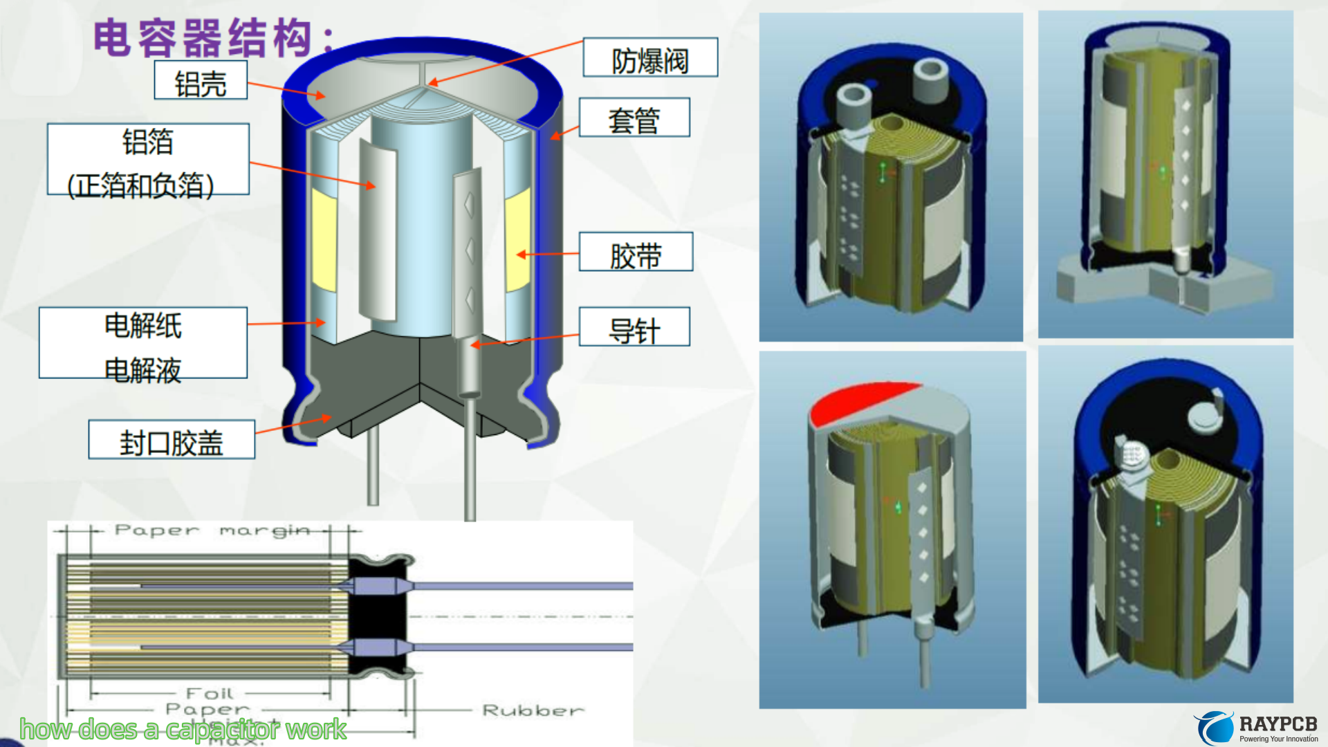
Electrolytic Capacitor Markings

Electrolytic capacitors are usually large enough to print the full value directly on the body. A typical marking looks like this:

470ยตF 35V 105ยฐC

Breaking that down:

Marking ElementExampleMeaning
Capacitance value470ยตF470 microfarads
Voltage rating35VMaximum operating voltage
Temperature rating105ยฐCMax operating temperature
Polarity stripeWhite/light stripe on bodyIndicates negative terminal
Longer leadPositive leadAnode (+)
Shorter leadNegative leadCathode (โˆ’)

The negative stripe runs the full height of the can and is clearly visible. On PCBs, the silkscreen will show a “+” marker for the positive pad. Always cross-reference both.

Film Capacitor Markings

Film capacitors follow a similar convention to ceramics but are large enough to print readable values. You’ll see markings like 0.1ยตF 250V or 100nF 63V. The voltage rating on film caps tends to be high โ€” they’re often used in mains-connected circuits.

How to Read Capacitor Markings on Ceramic Capacitors

This is where things get technical. Small ceramic capacitors โ€” especially SMD types โ€” have almost no room for printing, so they use compact code systems.

The 3-Digit Capacitance Code (EIA Standard)

The most widely used ceramic capacitor marking system uses a 3-digit number. The result is always expressed in picofarads (pF).

Rule: First two digits = significant figures. Third digit = number of zeros (multiplier).

3-Digit Capacitor Code Chart

Marking CodeCalculationValue in pFConverted Value
01001 ร— 10โฐ1 pF1 pF
10010 ร— 10โฐ10 pF10 pF
10110 ร— 10ยน100 pF100 pF
10210 ร— 10ยฒ1,000 pF1 nF
10310 ร— 10ยณ10,000 pF10 nF / 0.01 ยตF
10410 ร— 10โด100,000 pF100 nF / 0.1 ยตF
10510 ร— 10โต1,000,000 pF1 ยตF
22022 ร— 10โฐ22 pF22 pF
22122 ร— 10ยน220 pF220 pF
47247 ร— 10ยฒ4,700 pF4.7 nF
68368 ร— 10ยณ68,000 pF68 nF
33433 ร— 10โด330,000 pF330 nF

Special case โ€” the “9” multiplier: When the third digit is 9, it means ร— 0.1. So “229” = 22 ร— 0.1 = 2.2 pF.

Tolerance Code Letters on Ceramic Capacitors

After the 3-digit value code, a single letter indicates the tolerance โ€” how close the actual capacitance is to the marked value:

Letter CodeToleranceUse Case
Aยฑ0.05 pFUltra-precision RF
Bยฑ0.1 pFPrecision RF, oscillators
Cยฑ0.25 pFRF matching
Dยฑ0.5 pFHigh-precision circuits
Fยฑ1%Precision filters, timing
Gยฑ2%General precision
Jยฑ5%Standard signal circuits
Kยฑ10%General purpose bypass
Mยฑ20%Power supply decoupling
Z+80% / โˆ’20%Non-critical bulk use

For an IC decoupling application, K or M is fine. For a crystal oscillator load capacitor or an active filter, you need F or better.

Voltage Rating Codes on Ceramic Capacitors

When space allows, a letter or number-letter code indicates the voltage rating:

CodeVoltage Rating
0G4 V
0J6.3 V
1A10 V
1C16 V
1E25 V
1H50 V
1J63 V
2A100 V
2D200 V
2E250 V
2H500 V
3A1000 V

On many small SMD ceramics (0402, 0201), voltage and tolerance codes are omitted entirely due to space constraints โ€” you have to check the reel label or datasheet.

Temperature Coefficient Codes โ€” The Dielectric Identifier

One of the most important (and most overlooked) capacitor markings is the temperature coefficient code. This tells you what dielectric material is used and how the capacitance will behave across temperature.

EIA Temperature Coefficient Codes for Ceramic Capacitors

CodeAlso Known AsTemp RangeCapacitance ChangeBest Use
C0GNP0โˆ’55ยฐC to +125ยฐCยฑ30 ppm/ยฐC (virtually zero)RF, oscillators, precision timing
X5Rโ€”โˆ’55ยฐC to +85ยฐCยฑ15%General SMD decoupling
X7Rโ€”โˆ’55ยฐC to +125ยฐCยฑ15%Wide-temp decoupling, filtering
X8Rโ€”โˆ’55ยฐC to +150ยฐCยฑ15%High-temp automotive
Y5Vโ€”โˆ’30ยฐC to +85ยฐC+22% / โˆ’82%Non-critical bypass only
Z5Uโ€”+10ยฐC to +85ยฐC+22% / โˆ’56%Older designs, avoid for new work

This is the marking that trips up engineers most often. A Y5V capacitor can lose over 80% of its rated capacitance at temperature extremes or under DC bias. If your schematic calls for 10ยตF X7R and you substitute Y5V “because it’s the same value,” the circuit may not work correctly in real conditions.

Decoding the EIA temperature code system:

The code uses a three-part structure. For X7R as an example:

  • Xย = lower temperature limit (โˆ’55ยฐC)
  • 7ย = upper temperature limit (125ยฐC)
  • Rย = maximum capacitance change (ยฑ15%)
First LetterLower Temp Limit
Xโˆ’55ยฐC
Yโˆ’30ยฐC
Z+10ยฐC
Middle NumberUpper Temp Limit
2+45ยฐC
4+65ยฐC
5+85ยฐC
6+105ยฐC
7+125ยฐC
8+150ยฐC
9+200ยฐC
Last LetterMax Capacitance Change
Pยฑ10%
Rยฑ15%
Sยฑ22%
T+22% / โˆ’33%
U+22% / โˆ’56%
V+22% / โˆ’82%

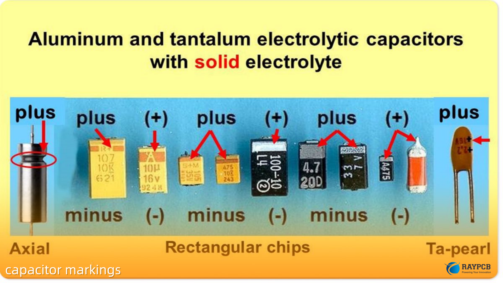
Tantalum Capacitor Markings

Tantalum capacitors are polarized and have their own marking convention. Most through-hole tantalum caps print the value directly (e.g., 4.7ยตF 16V) with a “+” marking on the positive lead.

SMD tantalum caps (the small rectangular ones with a stripe at one end) follow this convention:

Marking ElementDescription
Stripe / bandIndicates the POSITIVE terminal (opposite to electrolytic convention โ€” don’t confuse them)
Value codePrinted value in ยตF
Voltage codeLetter or number-letter system similar to ceramics

This is a critical difference to remember: on electrolytic caps, the stripe marks the negative terminal. On tantalum SMD caps, the stripe marks the positive terminal. Mixing this up is one of the most common capacitor polarity mistakes in SMD rework.

SMD Capacitor Package Sizes and What They Tell You

SMD capacitors don’t always have visible markings, but the package size itself communicates usable capacitance ranges:

Package CodeDimensions (mm)Typical Capacitance RangeTypical Use
02010.6 ร— 0.31 pF โ€“ 100 nFHigh-density RF, mobile
04021.0 ร— 0.51 pF โ€“ 10 ยตFGeneral SMD, decoupling
06031.6 ร— 0.81 pF โ€“ 22 ยตFStandard SMD design
08052.0 ร— 1.251 pF โ€“ 47 ยตFHigher capacitance SMD
12063.2 ร— 1.6100 pF โ€“ 100 ยตFHigh capacitance, power
12103.2 ร— 2.51 nF โ€“ 100 ยตFHigh voltage / high cap
18124.5 ร— 3.21 nF โ€“ 100 ยตFHigh voltage safety caps

When a ceramic cap has no printed marking at all โ€” which happens frequently on 0201 and 0402 parts โ€” your only way to identify it is from the reel label, the BOM, or by measuring with an LCR meter.

Complete Capacitor Marking Quick-Reference Chart

Marking TypeWhere FoundWhat to Look ForDecoding Method
3-digit code (e.g., 104)Ceramic, film capsThree numbersFirst 2 digits + zeros = pF value
Tolerance letter (e.g., K)Ceramic capsSingle letter after value codeSee tolerance table above
Voltage code (e.g., 1H)Ceramic capsLetter+number or number+letterSee voltage table above
Temp code (e.g., X7R)Ceramic caps3-character code on reel/datasheetSee EIA temp code table
Direct value (e.g., 470ยตF)Electrolytic, filmFull value printed on bodyRead directly
Polarity stripeElectrolyticStripe = negative terminalOpposite side is positive
Polarity stripeTantalum SMDStripe = positive terminalStripe side is positive
European notation (e.g., 4n7)Older componentsLetter used as decimal point4n7 = 4.7 nF

Useful Resources for Decoding Capacitor Markings

ResourceTypeLink
Digi-Key Capacitor Parametric SearchComponent Databasedigikey.com/capacitors
Murata Product CatalogDatasheet Librarymurata.com
TDK Capacitor FinderDatasheet Libraryproduct.tdk.com
KEMET Capacitor SelectorProduct Databasekemet.com
Vishay Capacitor DocumentsApplication Notesvishay.com/capacitors
Mouser Electronics SearchDistributor Databasemouser.com/capacitors
EIA-198 StandardIndustry Standardeia.org
All About CircuitsEducational Referenceallaboutcircuits.com

Frequently Asked Questions About Capacitor Markings

1. What does “104” mean on a ceramic capacitor?

The code “104” means 10 followed by 4 zeros in picofarads: 100,000 pF, which equals 100 nF or 0.1ยตF. This is the single most common decoupling capacitor value in digital electronics. You’ll see it on SMD ceramics and through-hole discs alike. The calculation is always: first two digits (10) ร— 10 to the power of the third digit (10โด) = 100,000 pF.

2. How do I tell the positive from negative terminal on a capacitor?

On through-hole electrolytic capacitors, the longer lead is positive and the can usually has a stripe marking the negative terminal. On SMD electrolytic caps, look for the “โˆ’” marking or stripe on the negative side. On SMD tantalum capacitors, the stripe or band marks the positive terminal โ€” the opposite convention from electrolytics. Non-polarized types like ceramic and film caps have no polarity and can be connected either way.

3. What does X7R mean on a capacitor?

X7R is a temperature coefficient code for ceramic capacitors. It means the capacitor operates from โˆ’55ยฐC (X) to +125ยฐC (7) with a maximum capacitance change of ยฑ15% (R) across that range. It’s a general-purpose dielectric โ€” better stability than Y5V/Z5U but not as precise as C0G/NP0. X7R is the most commonly specified dielectric for bypass and decoupling caps in commercial electronics.

4. Why do some SMD capacitors have no markings at all?

Very small SMD capacitors โ€” particularly 0201 and 0402 package sizes โ€” are often left blank because there simply isn’t enough surface area to print readable characters. The component identity is carried on the reel label and in the BOM. If you’ve lost track of a blank SMD capacitor, your only option is to measure it with an LCR meter and cross-reference the value with your design documentation.

5. What does the voltage rating on a capacitor marking mean, and can I use a higher-rated cap?

The voltage rating is the maximum DC voltage the capacitor can safely handle across its terminals. Exceeding it risks dielectric breakdown and component failure. Using a higher-rated capacitor is generally safe and often recommended โ€” a 50V-rated cap in a 12V circuit has more headroom and will typically last longer. Just verify that the physical size fits your footprint and that the capacitance value hasn’t shifted significantly due to the dielectric characteristics of the higher-voltage part.

Final Thoughts on Reading Capacitor Markings

Capacitor markings are a compact but information-dense system once you understand the rules. The 3-digit code gives you the value, the tolerance letter tells you accuracy, the voltage code sets your operating limit, and the temperature coefficient code (especially for ceramics) tells you how the component will behave across the real operating range of your product.

The polarity distinction between electrolytic and tantalum SMD caps is the one that bites engineers most often on rework โ€” so print out that reference table and keep it at your workbench. The few minutes spent learning to decode these markings will save you hours of troubleshooting bad boards.

How Does a Capacitor Work? Charge, Discharge & Electric Fields Explained

If you’ve ever touched a live PCB and felt a mild zap even after unplugging it, you’ve already had a very personal introduction to how a capacitor works. As a PCB engineer, capacitors are probably the components I interact with most โ€” and yet they’re still one of the most misunderstood passives on any board. This guide breaks down how does a capacitor work, from the basic physics of charge storage to the practical discharge curves you need to understand when designing real circuits.

What Is a Capacitor? (And Why Should You Care)

A capacitor is a passive two-terminal electrical component that stores energy in an electric field. Unlike a battery, which stores energy chemically, a capacitor stores it electrostatically โ€” and it can release that energy almost instantaneously. That’s what makes it so useful for decoupling, filtering, and energy buffering on a PCB.

At its most basic, a capacitor consists of:

  • Two conductive platesย (typically metal)
  • A dielectric materialย between them (insulating layer)
  • Two terminalsย connecting to the plates

The dielectric is key. It prevents current from flowing directly between the plates but allows an electric field to build up across them. The type of dielectric used โ€” ceramic, electrolytic, film, tantalum โ€” determines most of the capacitor’s electrical characteristics.

If you want to understand how a capacitor behaves on a PCB, you first need to understand what’s happening at the atomic level between those two plates.

The Physics Behind How a Capacitor Works

How Electric Charge Builds Up on the Plates

When you connect a capacitor to a voltage source, electrons from the negative terminal of the source are pushed onto one plate. This makes that plate negatively charged. Simultaneously, electrons are pulled away from the other plate, leaving it positively charged.

Here’s the counterintuitive part: no current actually flows through the dielectric. The charge just accumulates on the plates. The electric field created between them is what stores the energy.

The relationship between charge, capacitance, and voltage is expressed in one of the most fundamental equations in electronics:

Q = C ร— V

Where:

  • Qย = charge stored (coulombs)
  • Cย = capacitance (farads)
  • Vย = voltage across the capacitor (volts)

This equation tells you something very practical: a larger capacitance means you can store more charge at the same voltage. Double the capacitance, double the stored charge.

What Is an Electric Field Inside a Capacitor?

An electric field is a region where an electric force acts on charged particles. Inside a capacitor, the electric field points from the positive plate to the negative plate and is (ideally) uniform across the gap.

The strength of this electric field is:

E = V / d

Where d is the distance between the plates. This is why reducing the gap between plates increases the electric field strength โ€” and also why dielectric breakdown is a real failure mode if you exceed a capacitor’s voltage rating.

The energy stored in this electric field is given by:

W = ยฝ ร— C ร— Vยฒ

Notice the Vยฒ term. That means if you double the voltage, you quadruple the stored energy. This is exactly why high-voltage capacitors in power supplies can be genuinely dangerous even when the circuit is off.

Capacitance: What Determines It?

Capacitance isn’t arbitrary โ€” it’s determined by three physical factors:

FactorEffect on CapacitanceEngineer’s Takeaway
Plate area (A)Larger area = higher capacitanceBigger footprint = more capacitance
Plate separation (d)Smaller gap = higher capacitanceThin dielectrics give high values
Dielectric constant (ฮตr)Higher ฮตr = higher capacitanceMaterial choice drives performance

The formula is:

C = ฮตโ‚€ ร— ฮตr ร— A / d

Where ฮตโ‚€ is the permittivity of free space (8.854 ร— 10โปยนยฒ F/m).

This formula is what separates a 10pF ceramic cap from a 1000ยตF electrolytic. The electrolytic achieves its massive capacitance by using an extremely thin oxide layer as the dielectric (tiny d) and having an enormous effective plate area through a rolled foil construction.

How Does a Capacitor Charge? The RC Time Constant

When you connect a capacitor in series with a resistor to a DC voltage source, it doesn’t charge instantly. The charging follows an exponential curve governed by the RC time constant.

The Charging Equation

V(t) = V_source ร— (1 – e^(-t/RC))

Where:

  • Rย = resistance in ohms
  • Cย = capacitance in farads
  • RCย = the time constant (ฯ„, tau) in seconds
  • tย = time elapsed

The time constant ฯ„ = RC is the time it takes the capacitor to charge to approximately 63.2% of the supply voltage.

RC Charging Table

Time ElapsedVoltage (% of V_source)Charge Status
1ฯ„ (1 ร— RC)63.2%Charging fast
2ฯ„86.5%Slowing down
3ฯ„95.0%Nearly there
4ฯ„98.2%Almost full
5ฯ„99.3%Considered fully charged

In practice, PCB designers treat 5ฯ„ as “fully charged.” For a 10kฮฉ resistor and 100ยตF capacitor: ฯ„ = 1 second, so the cap is fully charged in about 5 seconds.

Why Doesn’t the Current Stay Constant During Charging?

At the moment you apply voltage, the capacitor looks like a short circuit โ€” current rushes in at its maximum rate (limited only by R). As charge builds up, the voltage across the capacitor opposes the source voltage, reducing the current. Eventually, the capacitor voltage equals the source voltage, and current drops to zero. This is exactly why capacitors block DC in steady state but allow transient current during switching events.

How Does a Capacitor Discharge?

Discharge is just the reverse process. If you remove the voltage source and connect the charged capacitor through a resistor, the stored energy is released.

The Discharge Equation

V(t) = Vโ‚€ ร— e^(-t/RC)

Where Vโ‚€ is the initial voltage across the capacitor.

RC Discharging Table

Time ElapsedVoltage (% of Vโ‚€)Energy Remaining
1ฯ„36.8%~13.5%
2ฯ„13.5%~1.8%
3ฯ„5.0%~0.25%
4ฯ„1.8%~0.03%
5ฯ„0.7%~0.005%

Notice how the energy drops much faster than the voltage โ€” that’s because energy scales with Vยฒ. This is an important design consideration when sizing bulk capacitors for hold-up circuits in power supplies.

Capacitors in AC vs. DC Circuits

Capacitors Block DC, Pass AC โ€” Here’s Why

In a DC circuit, once a capacitor is fully charged, current stops flowing. The capacitor essentially acts as an open circuit. This is why capacitors are used as coupling components โ€” they block DC bias while passing the AC signal riding on top of it.

In an AC circuit, the voltage is constantly changing, so the capacitor is always charging and discharging. Current appears to “flow through” the capacitor. The opposition to this current flow is called capacitive reactance:

Xc = 1 / (2ฯ€ ร— f ร— C)

Where f is frequency in Hz.

Capacitive Reactance vs. Frequency

FrequencyXc (for 100nF cap)Practical Meaning
10 Hz159,155 ฮฉBlocks audio sub-bass
1 kHz1,592 ฮฉPartial pass
100 kHz15.9 ฮฉGood bypass cap
10 MHz0.159 ฮฉNear short circuit
1 GHz0.0016 ฮฉRF bypass

This is why decoupling capacitors need to be selected based on the switching frequency of your IC โ€” not just slapped on arbitrarily.

Types of Capacitors and How Their Construction Affects Behavior

Understanding the internal construction of each type helps you make better choices on a PCB.

Ceramic Capacitors (MLCC)

Multi-layer ceramic capacitors (MLCCs) stack hundreds of alternating dielectric and electrode layers to achieve high capacitance in a tiny package. They have excellent high-frequency performance and low ESR (equivalent series resistance), making them the go-to decoupling cap on most PCBs.

Watch out for: Capacitance drop with DC bias voltage. A 10ยตF X5R MLCC rated at 10V might only deliver 3โ€“4ยตF when biased at 9V. Always check the derating curve in the datasheet.

Electrolytic Capacitors (Aluminum)

These use a wound aluminum foil with an extremely thin aluminum oxide dielectric. They achieve very high capacitance values (up to tens of thousands of ยตF) but are polarized โ€” connect them backwards and they will fail, sometimes spectacularly.

Watch out for: High ESR at high frequencies, limited lifetime (especially at elevated temperatures), and polarity. These are bulk storage and power-line filtering caps, not high-frequency decouplers.

Tantalum Capacitors

Tantalum caps offer better volumetric efficiency than aluminum electrolytics and lower ESR. But they’re infamous for failing short-circuit when exposed to voltage spikes โ€” which can cause board fires in extreme cases.

Watch out for: Always derate tantalum caps to 50% of their rated voltage for reliable operation. Never use them in inrush-prone environments without protection.

Film Capacitors

Polyester or polypropylene film caps are prized for their stability, low distortion, and predictable behavior over temperature. They’re common in analog audio, precision timing, and power factor correction circuits.

Capacitor Type Comparison Table

TypeCapacitance RangePolarityESRBest For
MLCC Ceramic1pF โ€“ 100ยตFNon-polarVery lowDecoupling, RF, signal
Aluminum Electrolytic1ยตF โ€“ 100,000ยตFPolarMedium-HighBulk storage, PSU filter
Tantalum0.1ยตF โ€“ 2,200ยตFPolarLowCompact power filtering
Film100pF โ€“ 100ยตFNon-polarLowAudio, timing, precision
Supercapacitor0.1F โ€“ 3,000FPolarVery lowEnergy storage, backup

Capacitor Parameters Every PCB Engineer Must Know

When selecting a capacitor for your design, the part number is just the beginning. These are the parameters that actually matter:

Capacitance (C): Nominal value in farads. Always verify against the derating curves.

Voltage Rating (V_rated): The maximum voltage the dielectric can withstand before breakdown. Always derate โ€” typically 80% for ceramics, 50% for tantalums.

ESR (Equivalent Series Resistance): The resistive loss inside the capacitor. High ESR means more heat generated during ripple current, and reduced effectiveness as a decoupling cap.

ESL (Equivalent Series Inductance): Every capacitor has parasitic inductance. Above the self-resonant frequency (SRF), the cap starts behaving like an inductor. For a 100nF MLCC, this might be at 50โ€“100 MHz.

Temperature Coefficient: Ceramic caps are classified by their temperature behavior โ€” C0G/NP0 caps are ultra-stable, X7R caps drift ยฑ15%, and Y5V caps can shift by -80% at temperature extremes.

Ripple Current Rating: Especially important for electrolytic caps in power supplies. Exceeding the ripple current spec is one of the leading causes of premature electrolytic failure.

Practical Applications: Where Capacitors Actually Earn Their Place

Decoupling and Bypass Capacitors

Every digital IC on a PCB needs decoupling capacitors placed as close to the power pins as physically possible. When the IC switches, it draws a sharp spike of current. The decoupling cap supplies this current locally, preventing the spike from propagating through the power plane as noise.

Typical strategy: 100nF MLCC per IC for high-frequency decoupling, with a 10ยตF bulk ceramic nearby.

Power Supply Filtering

The ripple on a rectified DC supply is smoothed by a large electrolytic capacitor. The larger the capacitance, the lower the ripple. But there’s a trade point โ€” larger caps mean more inrush current at startup.

RC Timing Circuits and Oscillators

The predictable RC time constant makes capacitors essential in timing circuits โ€” from simple 555 timer configurations to precision crystal oscillator load capacitors.

Signal Coupling and DC Blocking

In analog circuits, a series capacitor passes the AC signal between stages while blocking any DC offset. This prevents the bias point of one stage from disturbing the next.

Snubber Circuits

In switching power supplies and motor drives, RC snubbers (a resistor and capacitor in series across a switch) absorb the energy from voltage spikes caused by parasitic inductance during turn-off. Without them, these spikes can exceed the switch’s voltage rating and cause failures.

Common Capacitor Failures and What Causes Them

ailure ModeRoot CauseHow to Prevent
Dielectric breakdownOvervoltage or voltage spikeDerate voltage rating
Electrolytic dry-outHeat over timeOperate below temp rating
Tantalum short circuitVoltage spike, insufficient derating50% voltage derating
MLCC crackPCB flexing, thermal shockUse flex-crack resistant footprints
Capacitance lossDC bias effect (MLCC)Check derating curves at operating voltage
ESR degradationAge, high ripple currentSelect adequate ripple current rating

Useful Resources for Further Reading

Here are some authoritative references that are worth bookmarking:

  • Murata Capacitor Selector & SimSurfing:ย product.murata.comย โ€” search capacitors and view derating curves interactively
  • TDK MLCC Product Catalog & White Papers:ย product.tdk.comย โ€” excellent application notes on DC bias derating
  • Kemet SPICE Models & Parametric Search:ย kemet.comย โ€” download SPICE models for accurate simulation
  • IPC-2221B Standard (Generic Standard on Printed Board Design):ย Available via ipc.orgย โ€” PCB design rules including component placement guidelines
  • Wรผrth Elektronik Application Notes:ย we-online.comย โ€” free downloadable guides on passive component selection for EMC
  • All About Circuits (Reference):ย allaboutcircuits.comย โ€” well-structured textbook-style reference for RC circuit theory

Frequently Asked Questions About How Capacitors Work

1. Does current actually flow through a capacitor?

Not in the conventional sense โ€” electrons don’t physically cross the dielectric. What happens is that electrons accumulate on one plate and are simultaneously repelled from the other plate. In AC circuits, this continuous charge/discharge cycle produces a displacement current that makes it appear as though current is flowing through the capacitor.

2. Why does a capacitor block DC but pass AC?

In DC steady state, the capacitor charges up to the supply voltage and then current stops โ€” effectively an open circuit. In AC, the voltage constantly reverses, so the capacitor never fully charges in one direction. It continuously charges and discharges, allowing current to flow through the circuit.

3. What happens if you exceed a capacitor’s voltage rating?

The dielectric breaks down. For ceramics and films, this usually means a permanent short circuit. For electrolytics, it can result in venting, bulging, or in worst cases, an explosion. Always derate your voltage ratings โ€” I personally never run a ceramic cap above 80% of its rated voltage in a production design.

4. Why do electrolytic capacitors have polarity?

The dielectric of an electrolytic capacitor is a very thin layer of aluminum oxide, formed electrochemically on the surface of the aluminum foil. This oxide layer is directional โ€” it acts as a dielectric only when the anode (positive terminal) is at a higher potential than the cathode. Reverse the polarity and the oxide layer dissolves, shorting the cap. The resulting current causes rapid heating, gas buildup, and failure.

5. What is the self-resonant frequency (SRF) of a capacitor, and why does it matter?

Every real capacitor has parasitic inductance (ESL) from its leads and internal construction. At the SRF, the capacitive reactance equals the inductive reactance and they cancel โ€” the cap looks like a pure resistor (ESR). Above the SRF, the cap actually behaves inductively. This is critical for high-speed PCB design: a 100nF decoupling cap might have an SRF of 50 MHz. Above that frequency, it’s no longer decoupling โ€” it’s actually adding inductance to your power rail. That’s why high-speed designs use multiple cap values in parallel to extend the effective decoupling bandwidth.

What Is a Capacitor? A Complete Beginner’s Guide

If you’ve ever opened up a circuit board or watched an electronics tutorial, you’ve almost certainly come across a capacitor. They’re everywhere โ€” from the tiniest wearable devices to massive industrial power systems. Yet for many beginners (and even some seasoned hobbyists), the question what is a capacitor remains surprisingly fuzzy.

As a PCB engineer, I get asked this more than almost anything else. So let me walk you through everything you need to know about capacitors โ€” how they work, what types exist, how to read them, and how to use them correctly on a PCB. No unnecessary jargon. Just clear, practical knowledge.

What Is a Capacitor?

A capacitor is a passive electronic component that stores and releases electrical energy in the form of an electric field. Think of it like a tiny, fast-charging rechargeable battery โ€” but instead of using a chemical reaction, it stores energy between two conductive plates separated by an insulating material called a dielectric.

The fundamental job of a capacitor is to hold a charge temporarily and release it when needed. This makes it incredibly useful for smoothing power supplies, filtering signals, timing circuits, and coupling AC signals while blocking DC.

Every capacitor on a PCB plays a specific functional role โ€” and understanding that role is the first step to becoming a confident circuit designer.

How Does a Capacitor Work?

The Basic Operating Principle

At its core, a capacitor consists of two conductive plates (usually made of metal) placed very close together but not touching. Between them sits the dielectric โ€” an insulating material that prevents direct current from flowing through but allows an electric field to build up.

When you apply a voltage across the capacitor’s terminals:

  • Electrons accumulate on one plate (negative charge)
  • The opposite plate loses electrons (positive charge)
  • An electric field forms between the two plates
  • Energy is stored in that field

When the voltage source is removed or a load is connected, the capacitor discharges โ€” releasing that stored energy back into the circuit.

The Charging and Discharging Curve

Capacitors don’t charge or discharge instantly. They follow an exponential curve described by the RC time constant (ฯ„ = R ร— C), where R is the resistance in the circuit and C is the capacitance. After one time constant, a capacitor charges to about 63.2% of the supply voltage. After five time constants, it’s considered fully charged (~99.3%).

This behavior is exactly what makes capacitors so useful in timing circuits and filters.

Capacitance: The Key Measurement

What Is Capacitance?

Capacitance is the measure of a capacitor’s ability to store charge per unit of voltage. It is measured in Farads (F), named after physicist Michael Faraday.

In practice, most capacitors you’ll work with are measured in smaller units:

UnitSymbolEquivalent
MicrofaradยตF10โปโถ F
NanofaradnF10โปโน F
PicofaradpF10โปยนยฒ F
MillifaradmF10โปยณ F

Surface mount capacitors on a PCB often range from a few picofarads to several hundred microfarads, depending on their application.

What Affects Capacitance?

The capacitance of a capacitor depends on three physical factors:

FactorEffect on Capacitance
Plate area (A)Larger plates = higher capacitance
Distance between plates (d)Smaller gap = higher capacitance
Dielectric material (ฮต)Higher permittivity = higher capacitance

This relationship is expressed as: C = ฮต ร— (A / d)

Types of Capacitors

One of the most common areas of confusion for beginners is the sheer variety of capacitor types. Each type has its own characteristics, strengths, and ideal use cases. Here’s a comprehensive breakdown.

Ceramic Capacitors

Ceramic capacitors are the most widely used type in modern PCB design. They use a ceramic material as the dielectric and are available in a huge range of values from a few picofarads to tens of microfarads.

Key characteristics:

  • Non-polarized (can be connected either way)
  • Very low ESR (Equivalent Series Resistance)
  • Available in SMD packages (0201, 0402, 0603, 0805, etc.)
  • Temperature stability varies by class (C0G/NP0 most stable, X5R/X7R good for general use, Y5V poorest stability)

Best for: Decoupling/bypass capacitors, high-frequency filtering, general-purpose signal filtering

Electrolytic Capacitors

Electrolytic capacitors use an electrolyte solution to achieve very high capacitance values โ€” often from 1 ยตF up to tens of thousands of ยตF. They are polarized, meaning they must be connected with the correct polarity or they can fail catastrophically.

Key characteristics:

  • Polarized (has a positive and negative terminal)
  • Higher ESR than ceramics
  • Available in through-hole and SMD versions
  • Shorter lifespan at high temperatures

Best for: Power supply filtering, bulk energy storage, audio coupling stages

Tantalum Capacitors

Tantalum capacitors offer a middle ground โ€” higher capacitance density than ceramics but lower ESR and smaller size than electrolytics. They are also polarized.

Key characteristics:

  • Polarized
  • Compact and reliable
  • Sensitive to voltage spikes (can fail short if over-volted)
  • More expensive than ceramics or electrolytics

Best for: Portable electronics, medical devices, power supply decoupling where space is critical

Film Capacitors

Film capacitors use a thin plastic film as the dielectric. They are highly stable and have very low ESR and ESL (Equivalent Series Inductance).

Key characteristics:

  • Non-polarized
  • Excellent temperature stability
  • Low self-heating
  • Physically larger than other types

Best for: Audio circuits, precision timing, power factor correction, motor run capacitors

Supercapacitors (Ultracapacitors)

Supercapacitors are a class apart. They can store dramatically more energy than conventional capacitors โ€” sometimes hundreds or thousands of farads โ€” by using an electrochemical double-layer effect.

Key characteristics:

  • Very high capacitance (1F to 3000F+)
  • Low energy density compared to batteries, but much faster charge/discharge
  • Limited voltage rating (typically 2.5โ€“2.7V per cell)

Best for: Energy harvesting, backup power systems, regenerative braking, IoT devices that need brief power bursts

Capacitor Type Comparison Table

TypeCapacitance RangePolarized?ESRTypical Use
Ceramic (C0G)1pF โ€“ 1ยตFNoVery LowRF, precision
Ceramic (X7R)100pF โ€“ 10ยตFNoLowDecoupling
Electrolytic1ยตF โ€“ 100,000ยตFYesMedium-HighPower filtering
Tantalum0.1ยตF โ€“ 2,200ยตFYesLowPortable electronics
Film1nF โ€“ 100ยตFNoVery LowAudio, precision
Supercapacitor0.1F โ€“ 3,000FYesVery LowEnergy storage

How to Read Capacitor Values

Reading Through-Hole Capacitors

Most electrolytic capacitors are straightforward โ€” the value is printed directly on the body (e.g., “100ยตF 25V”). The longer lead is positive (+), and many have a stripe indicating the negative terminal.

Reading Ceramic Capacitor Codes

SMD and small ceramic capacitors often use a 3-digit code. Here’s how to decode it:

  • The first two digitsย are the significant figures
  • The third digitย is the multiplier (number of zeros to add)
  • The result is in picofarads (pF)

Example:

CodeCalculationValue
10410 ร— 10โด100,000 pF = 100 nF = 0.1 ยตF
10310 ร— 10ยณ10,000 pF = 10 nF
47247 ร— 10ยฒ4,700 pF = 4.7 nF
22022 ร— 10โฐ22 pF

Voltage Rating

Every capacitor has a voltage rating โ€” the maximum voltage it can safely handle. As a PCB engineer, I always recommend using a capacitor rated at at least 1.5ร— to 2ร— the maximum voltage it will see in the circuit. This provides a safety margin against voltage spikes and extends component life.

What Does a Capacitor Do in a Circuit?

Understanding what a capacitor actually does in different circuit contexts will save you hours of debugging. Here are the most common roles:

1. Decoupling / Bypass Capacitor

This is probably the most common use of a capacitor on a PCB. A small ceramic capacitor (typically 100nF) placed close to an IC’s power pin “decouples” it from the rest of the power supply. When the IC suddenly draws a burst of current, the capacitor supplies that current instantly โ€” preventing a voltage dip that could cause logic errors or noise.

2. Bulk Capacitance

Larger electrolytic or tantalum capacitors are placed across power rails to handle slower, larger current demands. Where decoupling caps handle high-frequency transients, bulk caps handle lower-frequency demand changes โ€” like when a motor starts or a display lights up.

3. Filtering

Capacitors are fundamental building blocks in filter circuits:

Filter TypeWhat It Does
Low-pass filterPasses low frequencies, blocks high frequencies
High-pass filterPasses high frequencies, blocks low frequencies
Band-pass filterPasses a specific frequency range
Notch filterRejects a specific frequency

A simple low-pass RC filter uses a resistor and capacitor in series, taking the output across the capacitor. The cutoff frequency is: f = 1 / (2ฯ€ ร— R ร— C)

4. Coupling / DC Blocking

In audio and RF circuits, a capacitor in series with a signal path passes AC (the audio or RF signal) while blocking DC offset. This is called AC coupling and is essential for connecting circuit stages with different DC bias levels.

5. Timing

In a classic 555 timer circuit, the time delay or oscillation frequency is set by an RC network. The capacitor charges and discharges through a resistor to create a predictable timing interval.

6. Energy Storage

In camera flash circuits, camera sensors, and power backup systems, capacitors store charge and then release it rapidly when needed. A camera flash is a perfect example โ€” the capacitor charges slowly from a small battery, then dumps that energy almost instantly through the flash tube.

Capacitor Specifications You Need to Understand

Before you select a capacitor for your design, you need to understand these key specifications:

SpecificationDescriptionWhy It Matters
Capacitance (C)Value in pF, nF, or ยตFDetermines the function in circuit
Voltage rating (V)Max operating voltageExceeding it damages/destroys the cap
ToleranceAccuracy of capacitance (ยฑ5%, ยฑ10%, ยฑ20%)Critical in precision circuits
ESREquivalent Series ResistanceAffects efficiency and heat generation
ESLEquivalent Series InductanceLimits high-frequency performance
Temperature coefficientHow much capacitance shifts with temperatureCritical in timing and RF circuits
Leakage currentSmall current through dielectricMatters in low-power and precision circuits
Lifetime / MTBFExpected service lifeKey for reliability engineering

Capacitors in Series and Parallel

Capacitors in Parallel

When capacitors are in parallel, their capacitances add together:

C_total = C1 + C2 + C3 + …

This is useful when you need a higher capacitance value but only have smaller caps available, or when you want to combine a bulk cap with a decoupling cap for wider frequency coverage.

Capacitors in Series

When capacitors are in series, the total capacitance decreases and follows this formula:

1/C_total = 1/C1 + 1/C2 + 1/C3 + …

For two equal capacitors in series: C_total = C/2

Series configurations are used when you need a higher voltage rating than any single capacitor provides.

How to Test a Capacitor

If you suspect a capacitor has failed, here are the most common testing methods:

Using a Multimeter

Set your multimeter to the capacitance measurement mode (if available) and measure across the capacitor terminals. Compare the reading to the marked value โ€” a significantly different reading indicates a failed component.

For electrolytic caps, you can also do a rough test in resistance mode:

  • Good capacitor:ย resistance briefly reads low, then climbs toward infinity
  • Short circuit:ย resistance stays near zero
  • Open circuit:ย no deflection at all

Using an LCR Meter

An LCR meter gives you capacitance, ESR, and sometimes dissipation factor (D) โ€” a much more thorough test. High ESR in an electrolytic capacitor is a common failure mode and is often missed by a basic multimeter.

Visual Inspection

For through-hole electrolytics, look for:

  • Bulging or domed tops (sign of internal pressure buildup)
  • Electrolyte leakage (brown crust around the base)
  • Cracked or damaged casing

Common Capacitor Failures and How to Avoid Them

Failure ModeCausePrevention
Dielectric breakdownExceeded voltage ratingDerate voltage to 50โ€“70% of rating
ESR increaseAge, heat, ripple currentUse proper temp-rated caps, add heat management
Short circuit (tantalum)Voltage spikeAdd inrush current limiting, use 2ร— derating
Capacitance driftTemperature extremesUse C0G/NP0 ceramics for stable applications
Mechanical failure (ceramic)PCB flex stressUse softer-termination caps on flexible areas

Capacitors on a PCB: Placement Best Practices

From years of hands-on PCB design, here are the placement rules I follow every time:

Decoupling caps must be placed as close as possible to the IC power pin โ€” ideally within 0.5mm. The connection from pad to via should be as short as possible. A decoupling cap placed 5mm away from the IC provides very little benefit at high frequencies.

For bulk capacitors, placement near the power input connector or the main regulator output is the priority. These are handling lower-frequency energy demands, so exact proximity is less critical than for decoupling.

If you’re working on a high-speed digital design, consider placing a 100nF and a 10nF ceramic in parallel for each IC โ€” the combination covers a wider frequency range than either alone.

Finally, avoid placing large electrolytic capacitors near heat-generating components. Heat is an electrolytic capacitor’s primary enemy โ€” it accelerates electrolyte evaporation and dramatically shortens lifespan.

Useful Resources for Learning More About Capacitors

Here are some authoritative resources to deepen your understanding:

ResourceTypeLink
Murata Capacitor Series GuideManufacturer Referencemurata.com
TDK Product SelectorComponent Databaseproduct.tdk.com
KEMET Capacitor FinderComponent Databasekemet.com
Vishay Capacitor CatalogDatasheet Libraryvishay.com
Digi-Key Capacitor Parametric SearchDistributor Databasedigikey.com
Mouser Capacitor SearchDistributor Databasemouser.com
IPC-2221 PCB Design StandardDesign Standardipc.org
All About Circuits โ€“ CapacitorsEducationalallaboutcircuits.com
Texas Instruments โ€“ Decoupling GuideApplication Noteti.com

Frequently Asked Questions (FAQs)

1. What is a capacitor in simple terms?

A capacitor is an electronic component that temporarily stores electrical energy as an electric field between two conductive plates. It charges up quickly when connected to a power source and releases that energy when needed. Unlike a battery, it stores energy electrostatically (not chemically), so it can charge and discharge extremely fast.

2. What is the difference between a capacitor and a battery?

Both store energy, but very differently. A battery stores energy chemically and can hold a large amount for a long time but charges and discharges slowly. A capacitor stores energy electrostatically, holds much less energy overall, but can charge and discharge almost instantly. This makes capacitors ideal for filtering, decoupling, and burst-energy applications rather than long-term energy supply.

3. Can I replace a capacitor with a higher capacitance value?

Sometimes, but it depends on the application. In power supply filtering, a higher value often works fine or even better. In timing circuits or filters, changing the capacitance directly changes the time constant or cutoff frequency and can break the circuit’s intended behavior. Always check the circuit design before substituting values.

4. Why do electrolytic capacitors have a polarity?

Electrolytic capacitors are manufactured using an electrochemical process that creates a very thin oxide layer on one metal plate โ€” this layer is the dielectric. This process is directional, which means the component only functions correctly (and safely) when connected with the correct polarity. Reverse-biasing an electrolytic can destroy the oxide layer, cause the capacitor to fail short, and sometimes lead to the capacitor venting or rupturing.

5. What happens if a capacitor is connected incorrectly on a PCB?

For non-polarized capacitors (like ceramics), there’s no polarity concern. For polarized types (electrolytic, tantalum), connecting them backwards can cause immediate or gradual failure. In high-current circuits, an incorrectly connected electrolytic capacitor can build up internal pressure and fail explosively. Always double-check polarity markings on both the component and the PCB silkscreen before powering up.


Final Thoughts

Understanding what a capacitor is and how it works is one of the most foundational skills in electronics. Whether you’re designing your first PCB, debugging a power supply, or just trying to understand why an IC keeps resetting, capacitors are almost always part of the story.

The key takeaways: capacitors store energy in an electric field, their behavior is defined by capacitance (measured in Farads), they come in many types each suited to specific jobs, and their placement on a PCB matters enormously for performance. Get these fundamentals right and you’ll make far fewer mistakes at the design stage โ€” and spend far less time troubleshooting later.

If you want to go deeper into how capacitors are used specifically in PCB layouts, I’d recommend exploring manufacturer application notes and PCB design guidelines from IPC โ€” they’re dense but packed with real-world engineering wisdom.