10 ยตF Capacitor: Bulk Decoupling, Audio & Power Supply Uses

“10uF Capacitor Types,” “Bulk Decoupling,” “Power Supply Applications,” “Audio Applications,” “PCB Layout Best Practices” all used as H2/H3 anchors

The 10uF capacitor has a specific, well-defined job in electronics: it sits at the boundary between the small ceramic bypass caps that kill high-frequency switching noise and the large bulk electrolytics that smooth out low-frequency supply ripple. Get that middle layer wrong โ€” wrong type, wrong placement, wrong voltage rating โ€” and your circuit pays for it with unstable regulators, noisy audio stages, and microcontrollers that misbehave under load transients.

This guide covers everything you need to know about the 10uF capacitor from a working PCB engineer’s perspective: how to read its markings, which dielectric type belongs where, how it integrates into power delivery networks, and what the common mistakes look like before they become expensive respins.

What Is a 10uF Capacitor? Value, Notation, and Markings

Understanding the 10ยตF Designation

The 10uF or 10ยตF designation means ten microfarads โ€” 10 ร— 10โปโถ farads. Like all capacitor values, it appears in several equivalent forms across catalogs and datasheets:

NotationEquivalent ValueCommonly Found On
10 ยตF10 microfaradsDatasheets, schematics
10 uF10 microfaradsASCII BOMs, PCB silkscreen
10,000 nF10,000 nanofaradsOccasionally in RF documentation
10,000,000 pF10 million picofaradsRarely used

How Is a 10uF Capacitor Marked?

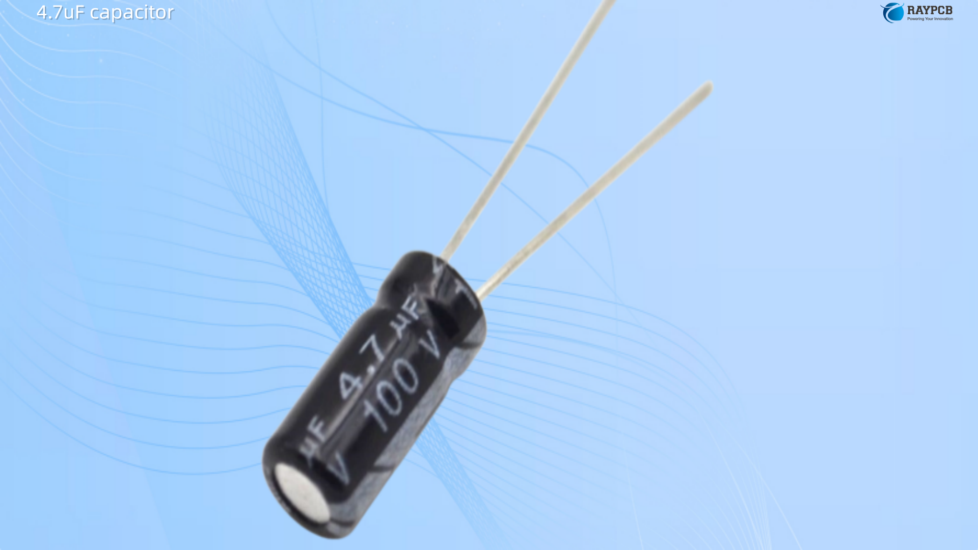
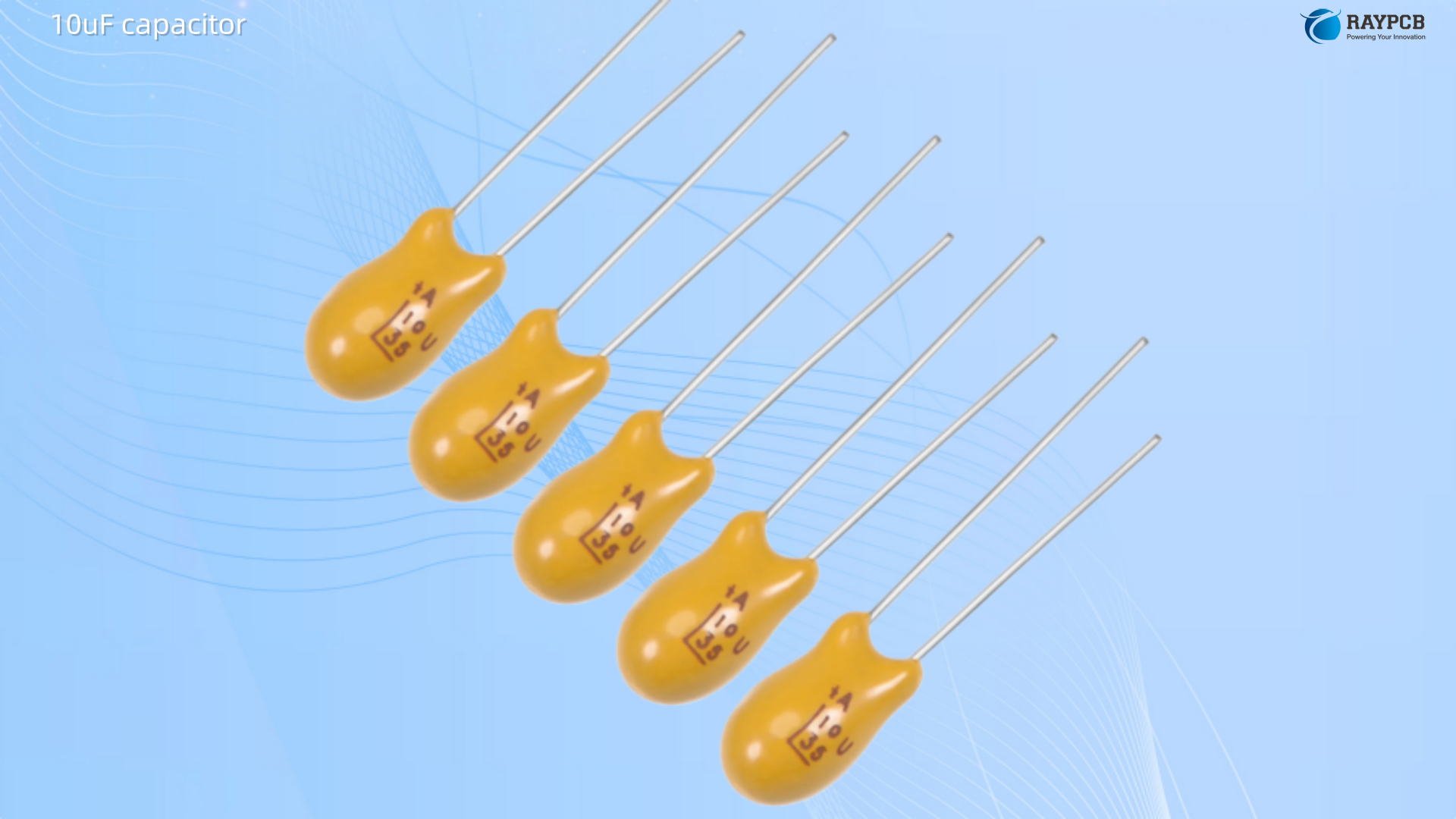
Through-hole electrolytic and tantalum capacitors almost always carry the value and voltage directly on the body โ€” “10ยตF 25V” or “10uF 50V” โ€” along with a polarity marking. The negative lead of an electrolytic is identified by a stripe, and the shorter lead is also negative. Tantalum parts mark the positive terminal.

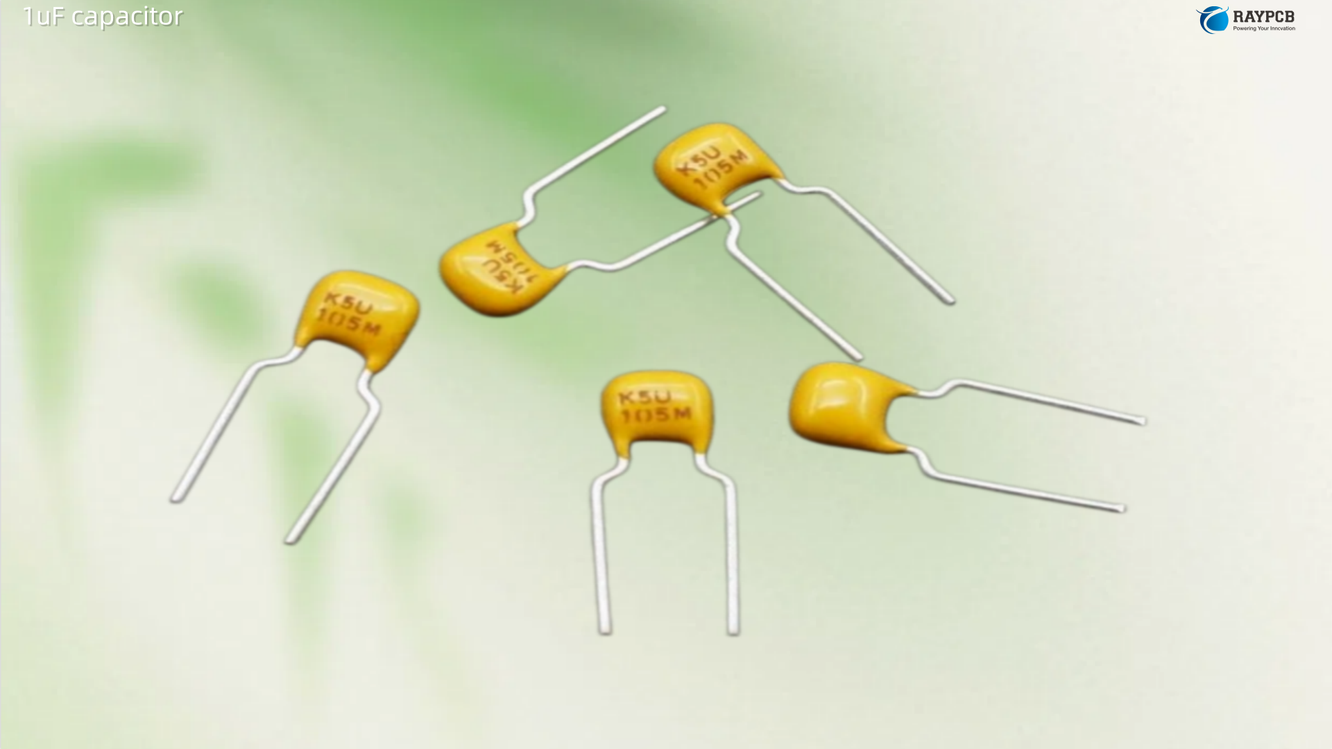
SMD electrolytic capacitors print the value on the top face. SMD MLCCs (multilayer ceramic capacitors) in 0805 and larger packages may carry a code; smaller 0402 and 0603 packages frequently carry no visible marking at all. This makes PCB assembly accuracy on a 10uF MLCC entirely dependent on reel labeling and BOM control โ€” a fact worth highlighting explicitly to any contract manufacturer handling your boards.

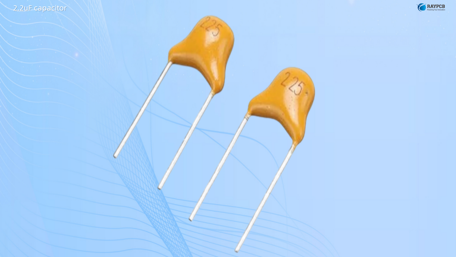
The 3-digit ceramic code for 10uF would be 106 (10 ร— 10โถ pF = 10,000,000 pF = 10 ยตF), though this marking system is less commonly used on parts this large since most 10uF caps are electrolytic or labeled directly.

10uF Capacitor Types: Which One Belongs Where

Choosing the right technology for a 10uF capacitor is not a trivial decision. The four main options โ€” aluminum electrolytic, tantalum, X5R/X7R MLCC, and polymer โ€” behave very differently under real operating conditions.

Aluminum Electrolytic

The classic choice for 10uF bulk decoupling. Aluminum electrolytics offer high capacitance-to-volume ratio, wide voltage ranges (from below 10V up to 500V), and low cost. Their weakness is ESR โ€” typically 0.5ฮฉ to 5ฮฉ depending on frequency and temperature โ€” and long-term reliability as the electrolyte slowly dries out, increasing ESR over the product lifetime. The electrolytic family provides an excellent, cost-effective low-frequency filter component because of the wide range of values and a high capacitance-to-volume ratio.

A 10uF 25V aluminum electrolytic is ideal for: bulk supply rail decoupling on audio boards, output filtering on linear regulators where some ESR is actually required for loop stability, and as a reservoir capacitor on longer PCB power traces.

Tantalum

Solid tantalum capacitors offer lower ESR than aluminum electrolytics (typically 0.1ฮฉ to 1ฮฉ), better high-frequency performance, and more stable capacitance over temperature. A 10uF solid tantalum in D or C case is a widely specified value on 5V and 3.3V supply rails for analog and mixed-signal ICs. The hard rule that must be respected: never place tantalum directly at a power supply input where inrush current is uncontrolled. Tantalum capacitors cannot handle surge current and a momentary reverse-voltage condition is catastrophic. A 10uF tantalum is the right choice for stable, current-limited mid-rail supply decoupling โ€” not as the first cap behind a power switch.

X5R / X7R MLCC

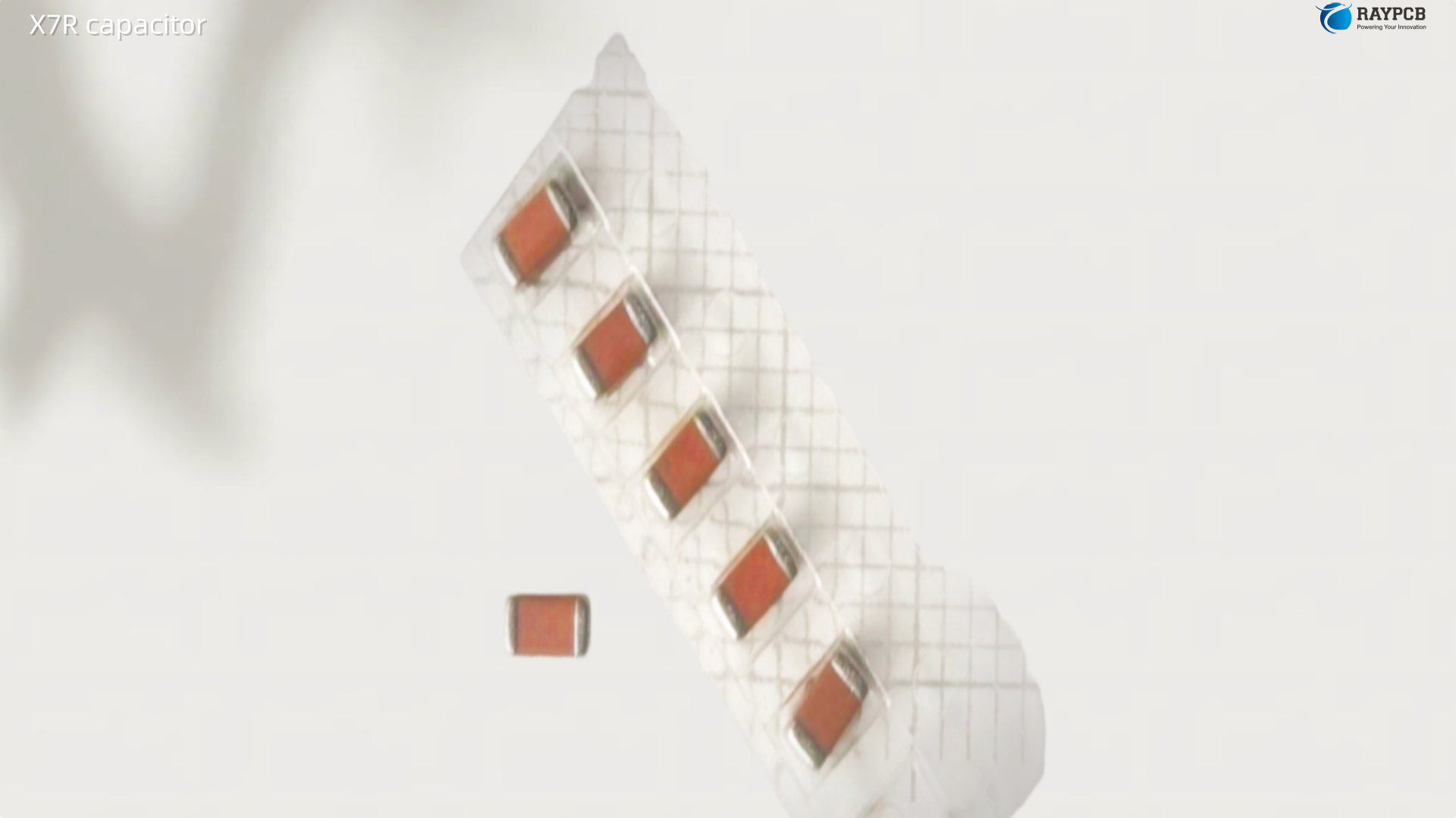
Modern 10uF X5R and X7R ceramic capacitors in 0805 and 1206 packages have become the default bulk decoupling solution for digital supply rails in board designs from the mid-2010s onward. They are non-polarized, have no aging mechanism, and offer the lowest ESR of any technology at this value. Some microcontroller manufacturers now explicitly recommend a 10uF ceramic capacitor on specific pins for internal voltage regulation circuits that require a charge reservoir.

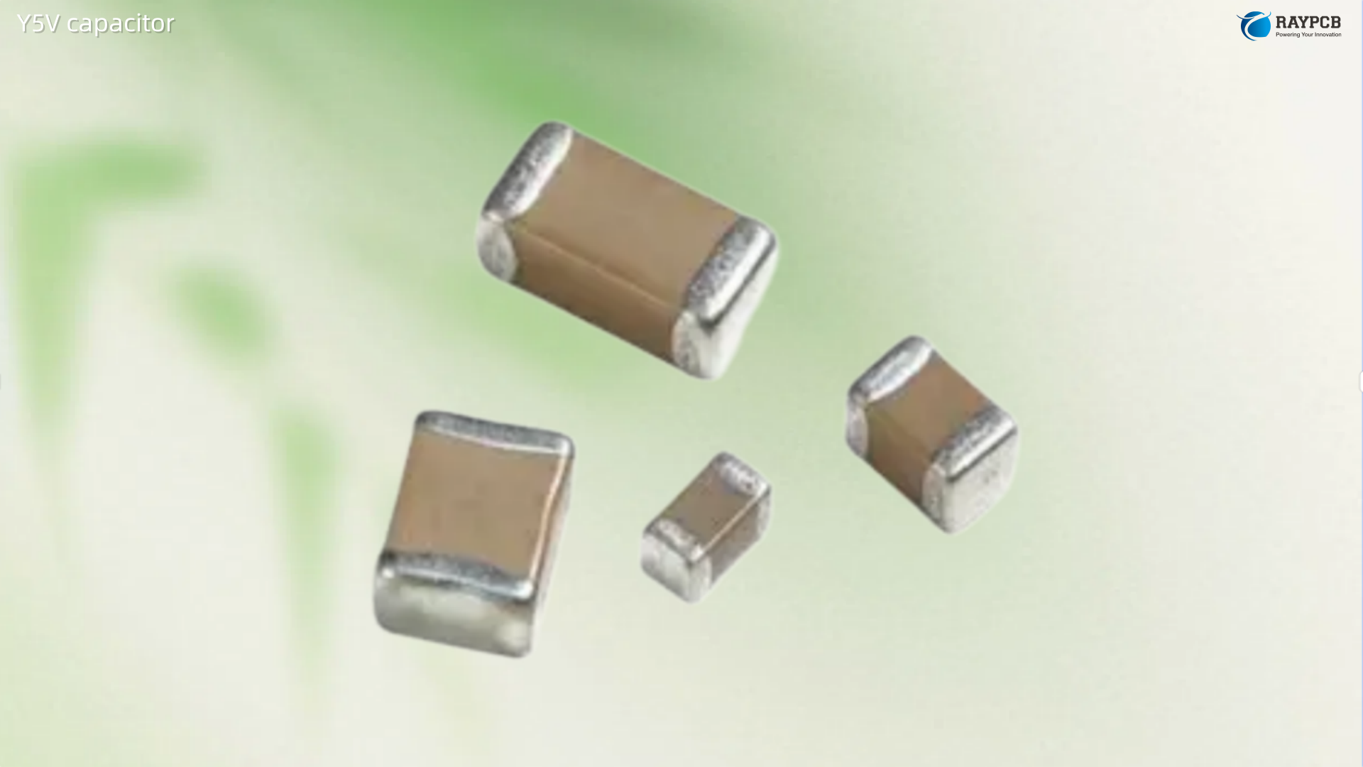
The unavoidable issue: DC bias derating. A 10uF X5R rated at 10V can lose 50% or more of its capacitance at 5V. A 10uF X7R at 10V rating may retain only 4โ€“6 ยตF under typical operating bias. Analog Devices explicitly recommends X5R or X7R dielectrics with 6.3V to 10V voltage ratings for 5V applications โ€” and warns that Y5V and Z5U dielectrics have poor characteristics versus temperature and DC bias, making them unsuitable for LDO bypass. The practical solution: specify a 10uF X5R or X7R at 25V or higher on any 3.3V or 5V rail to retain close to the full nominal capacitance in circuit.

Polymer Electrolytic

Polymer aluminum and polymer tantalum capacitors offer ESR comparable to MLCC parts โ€” far lower than wet electrolytic โ€” with high capacitance density. While more expensive per unit than electrolytics, polymer capacitors can offer cost savings over equivalent parallel MLCC arrays on high-current switching supply outputs. They do not suffer the piezoelectric effect that plagues ceramics in mechanically sensitive environments, making them attractive for audio power supply applications where MLCC microphonics could introduce noise.

10uF Capacitor Type Comparison

TypeTypical ESRPolarityVoltage RangeDC Bias StabilitySize/CostBest Application
Aluminum Electrolytic0.5โ€“5 ฮฉPolarized6.3Vโ€“450VGoodSmall/CheapBulk PSU, audio rails
Solid Tantalum0.1โ€“1 ฮฉPolarized4Vโ€“50VGoodMedium/ModerateMid-rail analog decoupling
X5R/X7R MLCC5โ€“50 mฮฉNone4Vโ€“100VPoor (derate)Tiny/ModerateDigital IC bypass
Polymer5โ€“30 mฮฉPolarized2.5Vโ€“25VGoodMedium/ExpensiveAudio PSU, DC-DC output

10uF Capacitor in Bulk Decoupling: The Three-Tier PDN Model

Why 10uF Is the Standard Bulk Decoupling Value

The power delivery network (PDN) of any non-trivial PCB needs to maintain low impedance across a wide frequency range โ€” from the kilohertz ripple generated by switching regulators up to the hundreds of megahertz demanded by fast digital ICs. No single capacitor value can do this efficiently alone.

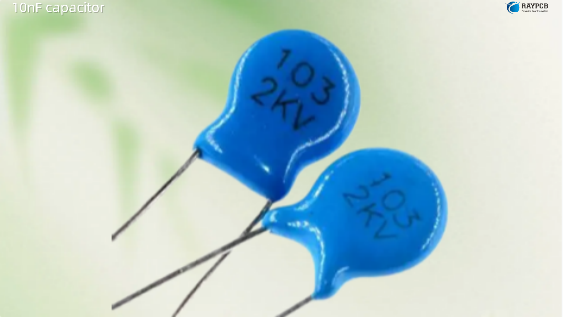
The standard three-tier decoupling approach works like this. The bulk capacitor โ€” commonly 10uF โ€” handles lower-frequency current demands and supply rail stabilization. Local bypass capacitors of 100nF handle high-frequency transients right at IC power pins. Smaller values (10nF or 1nF) address very-high-frequency noise where even 100nF parts have passed their self-resonant frequency.

A commonly used bulk capacitor value is 10uF with common local decoupling at 0.1uF or 1uF. The bulk capacitor is placed per voltage rail โ€” typically one 10uF near the power entry point for each voltage distribution on the board, with the bulk capacitance being 2 to 10 times the total local decoupling capacitance on the same bus.

The reason a 10uF electrolytic in parallel with a 100nF ceramic outperforms either part alone has nothing to do with simple capacitance addition. The electrolytic handles the lower-frequency switching current surges effectively; the ceramic, with its much lower parasitic inductance, covers the high-frequency transients that the electrolytic misses entirely once it hits series resonance and begins acting inductively. The electrolytic’s relatively higher ESR at high frequencies actually provides useful damping for the ceramic’s resonance โ€” the combination is more stable than two ceramics in parallel.

10uF Placement Strategy on the PCB

The capacitor placement strategy on a PCB matters as much as the value and type selection. Place at least one 10uF bulk capacitor per voltage rail on the board, near the power entry point or voltage converter output. For boards with multiple load clusters drawing significant current, a second 10uF at each cluster boundary prevents voltage sag propagating between sections.

Unlike 100nF bypass caps that absolutely must be within 1โ€“2 mm of their associated IC power pin, the 10uF bulk capacitor has more layout flexibility. Because it handles lower-frequency transients, the trace inductance to the load is less critical โ€” though “anywhere on the board” is still too casual. Keep bulk caps within a few centimeters of the major current consumers and use wide, short traces to minimize resistive voltage drop on heavy-current paths.

10uF Capacitor in Power Supply Applications

LDO Regulator Output Stability

The 10uF capacitor is almost universally specified as the output capacitor on modern LDO voltage regulators. This is not arbitrary. The LDO control loop stability depends critically on the output capacitor โ€” specifically its capacitance and ESR. A minimum capacitance (often 1uF to 10uF) is required to provide adequate phase margin in the feedback loop. Without sufficient output capacitance, the LDO oscillates.

The ESR dimension is where engineers get burned. Older LDO designs required a minimum ESR (often 0.1ฮฉ to 1ฮฉ) on the output capacitor to stay stable โ€” these parts were designed for tantalum outputs. Placing a very-low-ESR MLCC on such a regulator output can cause instability. Modern ceramic-stable LDOs (from suppliers including Texas Instruments, Analog Devices, and STMicroelectronics) are designed to work with 10uF ceramics at their outputs. The distinction is in the datasheet stability plots โ€” always check the ESR vs. capacitance region-of-stability chart before finalizing your output cap selection.

DC-DC Converter Output Filtering

At the output of a buck or boost converter, a 10uF ceramic or polymer capacitor performs output voltage ripple filtering. The output ripple voltage of a switching converter is approximately:

ฮ”V โ‰ˆ ฮ”I / (8 ร— f ร— C)

Where ฮ”I is the inductor ripple current, f is the switching frequency, and C is the output capacitance. For a converter switching at 500kHz with 200mA ripple current and a 10uF ceramic output cap: ฮ”V โ‰ˆ 0.2 / (8 ร— 500,000 ร— 0.00001) = 5 mV โ€” acceptably low for most digital loads. This calculation confirms why 10uF is so often the default output cap value in DC-DC reference designs.

RC Timing with 10uF

The RC time constant with a 10uF capacitor scales with resistor value as ฯ„ = R ร— C:

Resistor ValueTime Constant (ฯ„ = RC)Practical Application
1 kฮฉ10 msLED blink, debounce
10 kฮฉ100 msPower-on delay, reset hold
100 kฮฉ1 secondLong-delay timer circuits
1 Mฮฉ10 secondsSlow-discharge power hold

The 10uF electrolytic is commonly used as the timing capacitor in these applications, though its ยฑ20% tolerance and leakage current make it less accurate than a film or tantalum alternative at the same value. For precision timing requiring better than ยฑ5%, a 10uF film or tantalum cap at the cost premium is worthwhile.

10uF Capacitor in Audio Applications

Coupling Capacitors in Audio Circuits

A 10uF capacitor in series with an audio signal path creates a high-pass filter whose corner frequency is determined by the downstream load impedance. With a 10kฮฉ load: f = 1 / (2ฯ€ ร— 10,000 ร— 0.00001) โ‰ˆ 1.6 Hz โ€” well below audible range, meaning a 10uF coupling cap passes the full audio spectrum with negligible low-frequency attenuation.

For speaker-level coupling in amplifier output stages, however, 10uF is on the small side. Speaker impedances of 4ฮฉ or 8ฮฉ give corner frequencies of 4kHz and 2kHz respectively โ€” that would cut badly into the midrange. Speaker coupling capacitors need to be in the hundreds or thousands of microfarads. The 10uF audio coupling application is appropriate for line-level stages and headphone amplifiers where the downstream impedance is in the kilohm range.

Power Rail Decoupling in Audio Circuits

In audio and mixed-signal designs, power supply noise directly affects the noise floor and dynamic range of the circuit. Op-amp power supply rejection ratio (PSRR) falls at high frequencies โ€” an op-amp that suppresses 80dB of supply noise at DC may offer only 20dB at 1MHz. The 10uF bulk decoupling capacitor on the supply rail provides the energy reservoir that prevents supply voltage sag during high-current audio transients, and the parallel 100nF ceramic handles the higher-frequency switching noise that the 10uF electrolytic misses. The combination is standard practice in audio PCB design.

Microphony Warning for Ceramic 10uF in Audio

A genuine problem worth calling out: high-value X5R and X7R MLCCs exhibit piezoelectric microphony โ€” they physically vibrate at audio frequencies under AC signal voltages and generate measurable self-noise. At 10uF in a large 1206 package, this effect is more pronounced than in smaller values. For a 10uF capacitor sitting on an audio supply rail close to a sensitive preamplifier, a polymer capacitor or a low-microphony MLCC (Murata’s anti-vibration series, for example) is the safer choice over a generic X7R part.

PCB Layout Best Practices for 10uF Capacitors

Placement for Bulk Decoupling

Unlike 100nF bypass caps, which must live within a millimeter or two of the IC power pin, the 10uF bulk cap is less placement-critical in the high-frequency sense. Its job is to supply charge for slower transients โ€” the millisecond-scale current demands of microcontrollers booting up, audio outputs responding to transients, or regulators recovering from load steps. Place it at the power entry point to each board section, using short, wide traces to the power plane to minimize series resistance.

For digital boards with multiple IC clusters drawing more than 100mA combined, a dedicated 10uF per cluster provides local energy storage that prevents one section’s transient demand from pulling down another section’s supply voltage through shared trace impedance.

Polarity Marking and Assembly Verification

Reversed polarity on a 10uF electrolytic is a common assembly defect that causes immediate or delayed failure โ€” the capacitor’s ESR rises, it heats internally, and in worst cases it vents or ruptures. On your PCB silkscreen, always mark the positive terminal of electrolytic and tantalum footprints with a “+” and use a asymmetric pad layout (one pad larger than the other, or a chamfered corner on the positive pad) that makes correct orientation visually obvious. AOI inspection should include polarity checking for all polarized capacitors on the board.

Via Strategy for SMD 10uF Caps

For SMD bulk caps on 4-layer boards with inner power planes, route the capacitor directly from pad to via โ€” capacitor positive pad to power plane via, capacitor negative pad to ground plane via โ€” keeping the via as close to the pad as the design rules allow. Via-in-pad is ideal for high-current applications where every picohenry of loop inductance matters.

Useful Resources for 10uF Capacitor Selection

  • Murata SimSurfing:ย product.murata.com/en-global/tools/simsurfingย โ€” Model actual impedance vs. frequency and DC bias derating curves for 10uF MLCC parts; essential before committing to a ceramic part on a supply rail
  • Analog Devices AN-1099:ย analog.comย โ€” Comprehensive application note on bypass capacitor selection for LDOs, covering X5R vs X7R comparison, ESR effects, and piezoelectric noise
  • Analog Devices MT-101:ย analog.com/media/en/training-seminars/tutorials/MT-101.pdfย โ€” Decoupling techniques tutorial covering bulk vs local decoupling strategy with real impedance curves
  • KEMET Component Selector:ย kemet.comย โ€” Datasheets, SPICE models, and DC bias derating curves for 10uF electrolytic, polymer, and ceramic capacitors
  • TDK Capacitor Selector:ย product.tdk.comย โ€” Filter 10uF MLCCs by dielectric (X5R/X7R), voltage rating, and package to find appropriately derated parts
  • Sierra Circuits Decoupling Guide:ย protoexpress.com/blog/decoupling-capacitor-placement-guidelines-pcb-designย โ€” Practical PCB layout guidance for bulk and local decoupling capacitor placement

Frequently Asked Questions About the 10uF Capacitor

Q1: Can I replace a 10uF electrolytic capacitor with a 10uF ceramic capacitor? In most modern designs, yes โ€” with important caveats. A 10uF X5R or X7R MLCC has lower ESR, no polarity, no aging degradation, and smaller footprint. However, if the original design used an electrolytic on an LDO output that required minimum ESR for loop stability, substituting a very-low-ESR ceramic may cause oscillation. Always check the regulator’s datasheet stability region before swapping. For audio supply rails, be aware that large-value MLCCs exhibit piezoelectric microphony that electrolytics do not. Additionally, specify the ceramic at a voltage rating 3โ€“5ร— the rail voltage to compensate for DC bias capacitance loss.

Q2: What voltage rating should I choose for a 10uF capacitor? For electrolytic and tantalum parts, a 25โ€“50% derating is standard practice โ€” a 5V rail warrants a 10V minimum rated part, though 16V or 25V is better practice for reliability and lifetime. For X5R/X7R MLCCs, the DC bias derating is severe enough that a 3ร— to 5ร— voltage derating is needed to retain close to the full nominal capacitance. On a 3.3V rail, use a 10uF X5R rated at 16V or 25V. On a 5V rail, use 10uF rated at 25V. Never use Y5V or Z5U dielectrics in bypass applications โ€” their capacitance loss with voltage and temperature is too large to be useful.

Q3: Why do most PCB designs use both a 10uF and a 100nF capacitor on the same supply rail? The two values serve different frequency ranges, and placing them in parallel covers both. A 10uF electrolytic handles lower-frequency supply variations below approximately 1 MHz, but its internal series inductance causes it to hit series resonance at a few hundred kHz โ€” above this frequency it behaves more like an inductor than a capacitor. A 100nF ceramic has much lower parasitic inductance and remains effective up to 50โ€“200 MHz. Together they achieve low PDN impedance across a wide frequency range that neither part could achieve alone. The total capacitance (10.1ยตF) is irrelevant โ€” the benefit is the extended frequency coverage and the electrolytic’s ESR damping of the ceramic’s resonance.

Q4: Is a 10uF ceramic capacitor better than a 10uF electrolytic for audio supply decoupling? For pure noise filtering on a digital supply rail, yes โ€” the ceramic’s lower ESR gives better high-frequency noise rejection. For analog audio circuits, the answer is more nuanced. High-value ceramics in 0805/1206 packages exhibit piezoelectric microphony that converts vibration and signal-induced mechanical stress into measurable electrical noise. For sensitive preamplifier and ADC supply rails, a polymer electrolytic or a tantalum may actually produce quieter results than a generic X7R ceramic, even though the ceramic’s ESR is lower. The practical approach is to use a low-microphony MLCC or polymer part on analog supply rails and standard X7R ceramics on digital rails.

Q5: How do I identify a 10uF capacitor if the markings are worn or unclear? Through-hole electrolytics can be measured directly with a component meter or multimeter with a capacitance function. For SMD parts, the best approach is to cross-reference with the design BOM and PCB reference designator. If the BOM is unavailable, use a precision LCR meter at 120 Hz (standard for electrolytics) โ€” a reading of 8โ€“12 ยตF with higher ESR suggests electrolytic, while a lower-ESR reading suggests ceramic or tantalum. For unmarked SMD MLCCs, the reel label or packing bag is the only reliable source unless you have access to the original placement files.

The 10uF capacitor earns its place on every serious board not through dramatic specifications but through consistent, reliable performance in the middle of the frequency spectrum where no other single component covers the ground quite as well. Choose the right dielectric for the rail type, derate the voltage on your ceramics properly, and place it where the current actually flows โ€” and this unremarkable component will do everything it’s supposed to do, every time.

10 nF Capacitor: Code 103 โ€” One of the Most Common Values in Electronics

10nF capacitor explained โ€” decode the 103 marking, compare dielectrics, calculate RC filters, and get practical design tips. Tables, FAQs & resources included.

If you’ve ever dug through a parts bin, sorted a reel of MLCCs, or squinted at a tiny ceramic disc trying to read its markings, you’ve almost certainly come across a 10nF capacitor. Marked with the code 103, this little component shows up in nearly every electronics design I’ve worked on over the past decade โ€” from simple Arduino projects to dense, multi-layer industrial control boards.

In this guide, I’m going to walk through everything a working engineer or serious hobbyist needs to know about the 10nF capacitor: how to decode its markings, where it gets used, which packages and dielectrics to pick, and the practical design tips that datasheets don’t always spell out.

What Does “10nF” Actually Mean?

A 10nF capacitor stores 10 nanofarads of electrical charge. Let’s put that number in context with the unit conversions you’ll use on a daily basis:

UnitValue
Picofarads (pF)10,000 pF
Nanofarads (nF)10 nF
Microfarads (ยตF)0.01 ยตF
Farads (F)10 ร— 10โปโน F

You’ll see all four of these representations on datasheets, schematic symbols, and BOM lists depending on the manufacturer and the region. European datasheets tend to favor nanofarads, while many American component distributors list the same part as 0.01 ยตF. Both refer to the exact same 10nF capacitor โ€” it’s just notation preference.

Decoding the 103 Capacitor Code

The “103” code stamped on ceramic capacitors follows a simple three-digit system that has been an industry standard for decades. Here’s how to read it:

The first two digits (10) represent the significant figures of the capacitance value. The third digit (3) is the multiplier โ€” it tells you how many zeros to add after those significant figures, with the result expressed in picofarads.

So: 10 ร— 10ยณ = 10,000 pF = 10 nF.

That’s it. Once you internalize this pattern, you can decode any ceramic capacitor code on sight.

Common Capacitor Codes at a Glance

Here’s a quick reference table for the codes you’ll run into most often alongside the 103:

CodeCapacitance (pF)Capacitance (nF)Capacitance (ยตF)
10010 pF0.01 nFโ€”
101100 pF0.1 nF0.0001 ยตF
1021,000 pF1 nF0.001 ยตF
10310,000 pF10 nF0.01 ยตF
104100,000 pF100 nF0.1 ยตF
1051,000,000 pF1,000 nF1 ยตF
224220,000 pF220 nF0.22 ยตF
47347,000 pF47 nF0.047 ยตF

What About the Letter After the Code?

Sometimes you’ll see a fourth character after “103” โ€” something like 103K or 103J. That letter indicates the tolerance of the capacitor:

Letter CodeTolerance
Jยฑ5%
Kยฑ10%
Mยฑ20%
Z+80% / โˆ’20%

A 103J capacitor is a 10nF capacitor with tight ยฑ5% tolerance, which is what you’d reach for in a precision filter or timing circuit. For general bypass and decoupling, 103K (ยฑ10%) is the go-to choice for most PCB engineers โ€” it’s cheaper, widely stocked, and good enough for the application.

Why the 10nF Capacitor Is So Popular

I’ve been asked this by junior engineers more than once: “Why do I see 10nF everywhere?” The answer comes down to a few practical realities.

First, 10nF sits right in the sweet spot between “too small to do much filtering” and “too large to respond quickly at high frequencies.” That makes it incredibly versatile. It’s large enough to smooth out minor voltage ripple on a power rail near a low-power IC, but small enough to have a low impedance at frequencies in the hundreds-of-kilohertz range where switching noise tends to live.

Second, the 10nF value is part of the E12 preferred number series, which means every major capacitor manufacturer produces it in every common package, dielectric, and voltage rating. Availability is never a problem. During the MLCC shortage a few years back, even when 100nF parts were on 52-week lead times, 10nF capacitors were comparatively easier to source.

Third, it’s cheap. At volume, a 10nF MLCC in an 0402 or 0603 package costs a fraction of a cent. There’s almost no reason not to place one wherever your design could benefit from a small amount of local energy storage or high-frequency filtering.

Key Specifications to Check Before You Pick a 10nF Capacitor

Capacitance value is just the starting point. If you’re selecting a 10nF capacitor for a real PCB design, here are the parameters that actually matter.

Voltage Rating

The voltage rating defines the maximum DC voltage the capacitor can handle continuously without risk of dielectric breakdown. For 10nF ceramic capacitors, common ratings include 10V, 16V, 25V, 50V, 100V, and in some specialized packages, up to 1kV or more.

My general rule of thumb: pick a voltage rating at least twice the maximum operating voltage in your circuit. Running a ceramic capacitor close to its rated voltage not only risks failure โ€” it actually reduces the effective capacitance due to DC bias effects, especially with X7R and X5R dielectrics.

ApplicationTypical Voltage Rating
3.3V / 5V digital logic decoupling16V or 25V
12V automotive circuits50V
AC mains-side filtering250V or higher (safety-rated)
General prototyping50V (a safe default)

Dielectric Type

This is where many beginner engineers go wrong. Not all 10nF capacitors behave the same way, and the dielectric material is the reason.

C0G / NP0: The gold standard for stability. Capacitance barely changes with temperature, voltage, or aging. Use this for precision timing circuits, oscillator feedback networks, and analog signal paths where accuracy matters. The downside is that C0G caps tend to be physically larger for the same capacitance and cost a bit more.

X7R: The workhorse dielectric. Good stability across the โˆ’55ยฐC to +125ยฐC range (within ยฑ15%), and available in very small packages. This is what you’ll use for 90% of your decoupling and general filtering needs with a 10nF capacitor. Just be aware that capacitance drops under DC bias โ€” a 10nF X7R rated at 25V might only deliver 7โ€“8 nF when you actually apply 20V across it.

Y5V / Z5U: Budget dielectrics with wide capacitance variation (up to +22% / โˆ’82% over the temperature range). Honestly, I avoid these for 10nF values. The capacitance swing is too unpredictable for most applications, and the price difference versus X7R is negligible at this value.

DielectricTemp RangeCapacitance StabilityBest For
C0G / NP0โˆ’55ยฐC to +125ยฐCยฑ30 ppm/ยฐCPrecision timing, analog, RF
X7Rโˆ’55ยฐC to +125ยฐCยฑ15%Decoupling, general filtering
X5Rโˆ’55ยฐC to +85ยฐCยฑ15%Low-voltage decoupling
Y5Vโˆ’30ยฐC to +85ยฐC+22% / โˆ’82%Non-critical, cost-sensitive

Package Size (SMD)

For surface-mount designs, the 10nF capacitor is available in virtually every standard package. Here’s what I typically use:

PackageDimensions (mm)Typical Use Case
02010.6 ร— 0.3Ultra-compact mobile, wearables
04021.0 ร— 0.5High-density PCBs, smartphones
06031.6 ร— 0.8General-purpose SMD designs
08052.0 ร— 1.25Easy hand-soldering, prototyping
12063.2 ร— 1.6Higher voltage, power applications

For through-hole work โ€” breadboard prototyping, audio circuits, or repair jobs โ€” the classic ceramic disc capacitor with “103” printed on it is still the most recognizable form of the 10nF capacitor.

Practical Applications of the 10nF Capacitor

Let me walk through the real-world circuits where I reach for a 10nF capacitor on a regular basis.

Decoupling and Bypass Filtering

This is the number-one use case. Place a 10nF capacitor as close as possible to the power and ground pins of an IC โ€” especially op-amps, microcontrollers, and ADCs. It acts as a local charge reservoir that absorbs high-frequency current spikes before they propagate back through your power distribution network.

Many reference designs use a combination approach: a 100nF (104) capacitor for broadband decoupling paired with a 10nF (103) capacitor to extend the effective filtering to higher frequencies. The two values complement each other nicely because the 10nF cap has lower impedance at frequencies above roughly 10โ€“20 MHz where the 100nF cap’s self-resonance starts to roll off.

RC Low-Pass Filters

Pair a 10nF capacitor with a resistor, and you’ve got a simple first-order low-pass filter. The cutoff frequency is calculated using the formula:

f_c = 1 / (2ฯ€ ร— R ร— C)

Here are some practical cutoff frequencies for common resistor pairings with a 10nF capacitor:

Resistor (R)Cutoff Frequency (f_c)
1 kฮฉโ‰ˆ 15.9 kHz
4.7 kฮฉโ‰ˆ 3.39 kHz
10 kฮฉโ‰ˆ 1.59 kHz
47 kฮฉโ‰ˆ 338 Hz
100 kฮฉโ‰ˆ 159 Hz

This makes the 10nF capacitor extremely useful for anti-aliasing filters ahead of ADCs, audio tone shaping, and smoothing sensor outputs (like thermistor or photodiode readings) before digital sampling.

Signal Coupling and DC Blocking

In audio and analog circuits, a 10nF capacitor can serve as a coupling capacitor to pass AC signals between stages while blocking DC offset. At 10nF, the impedance at 1 kHz is roughly 15.9 kฮฉ, which means it starts to attenuate signals below a few hundred hertz depending on the load impedance. This makes it more suited for RF and high-frequency coupling rather than full-range audio coupling (where you’d typically reach for 100nF or higher).

Timing and Oscillator Circuits

Used with a 555 timer, comparator, or microcontroller oscillator input, a 10nF capacitor sets the timing constant alongside a resistor. The small value means faster charge/discharge cycles, which translates to higher oscillation frequencies. For instance, in a basic 555 astable configuration, a 10nF timing capacitor with a 10 kฮฉ resistor network will produce frequencies in the low kilohertz range โ€” useful for generating audible tones or clock pulses.

Thermistor and Sensor Interface Filtering

This is one that doesn’t get talked about enough. When you wire a thermistor (NTC or PTC) to a microcontroller ADC input, the long wire runs often pick up electrical noise โ€” especially in industrial or automotive environments. Placing a 10nF capacitor at the ADC pin filters out high-frequency interference and gives you much cleaner temperature readings. It’s a simple addition that can dramatically improve measurement accuracy.

EMI Suppression on Signal Lines

On high-speed digital signal traces โ€” UART, SPI clock lines, IยฒC buses โ€” a strategically placed 10nF capacitor to ground can suppress high-frequency ringing and EMI. This is particularly useful when passing signals between boards or through connectors, where impedance discontinuities can cause reflections.

How to Read 10nF Capacitor Markings

Different form factors use different marking conventions. Here’s a quick summary so you’re never stuck guessing:

Capacitor TypeHow the 10nF Value Appears
Ceramic disc (through-hole)“103” printed on body
MLCC (SMD, small packages)Usually unmarked โ€” verify from reel label or BOM
MLCC (SMD, larger 0805/1206)May show “103” or be unmarked
Film capacitor“10n” or “0.01ยตF” or “.01” printed on body
Tantalum (rare at 10nF)Alphanumeric code, e.g., “A4” (EIA code)
ElectrolyticNot available at 10nF โ€” too small a value

The key gotcha with SMD MLCCs: most small packages (0402, 0603) carry no markings at all. The only way to identify them on a populated board is through the BOM, the assembly drawing, or measurement with a capacitance meter. This is one reason I always maintain a meticulous BOM and assembly documentation for every design.

Design Tips from the Bench

After years of placing 10nF capacitors on boards, here are some lessons I’ve picked up:

Keep decoupling caps close to IC pins. This sounds basic, but I still review designs where bypass capacitors are placed centimeters away from the IC they’re supposed to protect. The parasitic inductance of even a few millimeters of trace reduces the capacitor’s effectiveness at high frequencies. Place your 10nF cap within 2โ€“3 mm of the power pin, and route the ground connection through the shortest possible via to the ground plane.

Don’t rely on a single capacitor value for decoupling. A multi-value approach (for example, 10nF + 100nF + 10ยตF) covers a wider frequency range. The 10nF cap handles the highest frequency noise, the 100nF covers the midrange, and the 10ยตF bulk cap handles low-frequency transients.

Check DC bias derating for X7R and X5R. As I mentioned earlier, ceramic capacitors with Class II dielectrics lose effective capacitance under DC bias. Use the manufacturer’s SEAT (Simulation of Electrical Attributes with Temperature) tools or DC bias curves to verify your 10nF capacitor actually delivers close to 10nF in your operating conditions.

Use C0G for anything analog-critical. If your 10nF capacitor is part of a filter, oscillator, or measurement path where capacitance accuracy matters, spend the extra fraction of a cent on a C0G part. The stability is worth it.

Useful Resources for Working with 10nF Capacitors

Here are some tools, datasheets, and references that I keep bookmarked:

ResourceDescriptionLink
Murata SimSurfingImpedance/frequency simulation for MLCCs including DC bias curvesmurata.com/tool
Samsung MLCC LibraryDownloadable SPICE models and datasheetssamsungsem.com
TDK Product CenterMLCC specifications, characteristic dataproduct.tdk.com
DigiKey RC Filter CalculatorQuick cutoff frequency calculatordigikey.com
Capacitor Code Chart (PDF)Printable 3-digit code referencesynthrotek.com
Kemet Capacitor SimulatorDC bias and temperature simulation for KEMET partskemet.com
LCSC / JLCPCB Parts LibraryAffordable MLCC sourcing with PCB assemblyjlcpcb.com

Frequently Asked Questions About the 10nF Capacitor

What is the value of a 103 capacitor?

A capacitor marked with the code 103 has a capacitance of 10 nanofarads (10nF), which is the same as 0.01 ยตF or 10,000 pF. The code follows a standard three-digit system: the first two digits (“10”) are the significant figures, and the third digit (“3”) is the multiplier (10ยณ), with the result in picofarads. So 10 ร— 1,000 = 10,000 pF = 10 nF.

Can I substitute a 10nF capacitor with a different value?

It depends on the circuit. For decoupling and bypass applications, you can often substitute with nearby values like 4.7nF or 22nF without noticeable issues. However, in timing circuits, oscillators, or precision filters, even small deviations from 10nF will shift the frequency response or timing constant. Always check the circuit requirements before substituting.

What is the difference between a 10nF capacitor and a 100nF capacitor in decoupling?

Both are commonly used for IC decoupling, but they target different frequency ranges. A 100nF (104) capacitor is effective at suppressing noise in the low-to-mid MHz range, while a 10nF (103) capacitor has lower impedance at higher frequencies (tens of MHz and above). Many designs use both values together for broadband noise suppression across a wider frequency spectrum.

Are 10nF capacitors polarized?

No. The vast majority of 10nF capacitors are ceramic types (either through-hole discs or SMD MLCCs), and these are non-polarized. You can install them in any orientation. Polarized capacitors (electrolytics and tantalums) are generally not manufactured in values as small as 10nF.

How do I measure a 10nF capacitor if it has no markings?

Use a digital multimeter with a capacitance measurement function. Set it to the nanofarad range, connect the capacitor leads to the measurement terminals, and read the value. Most decent multimeters can measure capacitance accurately down to the low pF range. For SMD parts that are already soldered to a board, you’ll need to desolder the component first โ€” in-circuit measurements will give inaccurate readings because you’ll be measuring the entire parallel network on that node, not just the individual capacitor.

Wrapping Up

The 10nF capacitor, humbly marked with the code 103, is one of those components that quietly makes modern electronics work. It’s not glamorous. Nobody writes marketing copy about a bypass cap. But from the decoupling network on a microcontroller to the anti-aliasing filter on an ADC input, this value earns its place in nearly every design.

If you’re building a parts kit for your bench, keep a healthy stock of 10nF capacitors in both 0603 and 0805 packages, in X7R dielectric with a 50V rating. That single combination will cover the majority of your prototyping and production needs. And if you’re designing for precision, grab a handful of C0G variants too โ€” you’ll thank yourself later when your filter response matches the simulation.

Good design isn’t just about picking the right value. It’s about understanding why that value works, knowing where to place it on the board, and respecting the parameters that the datasheet tries to tell you about. The 10nF capacitor is a perfect example: simple on the surface, but full of nuance once you dig in.

4.7 ยตF Capacitor: The Standard Output Cap for Voltage Regulators

“4.7uF as Standard LDO Output Capacitor,” “DC-DC Converter Applications,” “Audio Circuit Applications,” “PCB Layout Essentials” all used as section anchors

The 4.7uF capacitor appears on more reference schematics, evaluation boards, and production designs than almost any other passive component value at its size. Open almost any LDO datasheet, buck converter reference design, or microcontroller application note and you’ll find a 4.7ยตF specification at the output pin, often in parallel with a 100nF ceramic. It’s not an accident. The 4.7uF value sits in a precise engineering sweet spot โ€” large enough to maintain regulator loop stability and handle load transients, small enough to avoid excessive inrush current and fit into compact SMD packages.

But picking any 4.7uF and calling it done is a fast path to field failures, oscillating regulators, and EMC pre-compliance surprises. This guide covers what the 4.7uF capacitor actually does in each application, which dielectric technology belongs where, and the PCB layout decisions that determine whether it performs as intended.

What Is a 4.7uF Capacitor? Value, Units, and Markings

Understanding the 4.7ยตF Designation

The notation 4.7uF (or 4.7ยตF) means 4.7 microfarads โ€” 4.7 ร— 10โปโถ farads. It appears in several equivalent forms:

NotationEquivalentWhere You’ll See It
4.7 ยตF4,700 nFDatasheets, schematics
4.7 uF0.0000047 FASCII BOMs, PCB silkscreen
4700 nF4,700,000 pFOccasionally in RF/filter references
4.7 ร— 10โปโถ Fโ€”SPICE simulation netlists

When a regulator datasheet specifies a 4.7ยตF output capacitor and your supplier’s catalog lists “4700nF 16V X5R 0805,” those are the same component value. Getting this wrong wastes time and occasionally money.

How a 4.7uF Capacitor Is Marked

Electrolytic through-hole parts print the value and voltage directly on the sleeve โ€” “4.7ยตF 50V” or “4.7uF 25V” โ€” with a stripe identifying the negative lead. SMD electrolytic parts mark the top face similarly. SMD MLCC parts in 0805 and larger packages may carry a numeric code; in 0402 and 0603 packages there is typically no visible marking at all. This means a 4.7uF 0402 X5R cap and a 4.7uF 0402 X7R cap are visually indistinguishable once they leave the reel. Your BOM, placement files, and assembly traveler must carry this information unambiguously โ€” it cannot be inferred from the board.

4.7uF Capacitor Types: Dielectrics, Performance, and Tradeoffs

Getting the dielectric type right for a 4.7uF capacitor is arguably more important than for smaller values, because this value is so often used in stability-critical LDO output applications where wrong dielectric selection produces oscillating regulators.

Aluminum Electrolytic

The classic through-hole choice for a 4.7uF at elevated voltages. A 4.7uF 50V radial electrolytic is inexpensive, has a well-understood ESR range (typically 1โ€“10ฮฉ at 120Hz), and has no DC bias capacitance loss. The weakness is high-frequency performance โ€” above a few hundred kHz the electrolytic’s internal series inductance causes it to resonate and then behave inductively, making it ineffective at high-frequency noise filtering without a parallel ceramic cap. Aging is the other concern: the electrolyte slowly evaporates over time, increasing ESR and reducing effective capacitance. Budget industrial designs or anything running at โ‰ค85ยฐC with a 10-year lifespan target need to account for electrolytic aging in their reliability analysis.

Solid Tantalum

A 4.7uF solid tantalum in B or C case was historically the default LDO output capacitor on 3.3V and 5V rails. Tantalum’s ESR (typically 0.1โ€“1ฮฉ) is stable across temperature, it has no aging mechanism, and it retains its capacitance far better under DC bias than X5R/X7R ceramics. The ESR in this range was actually beneficial for older LDO topologies that required a minimum ESR on the output capacitor for loop stability. The risks: tantalum is polarized and catastrophically fails on reverse voltage, it cannot handle surge current at power-up, and it is significantly more expensive per unit than a ceramic equivalent. In modern designs where the regulator is ceramic-stable, tantalum at 4.7uF is increasingly hard to justify on cost alone.

X5R and X7R MLCC (The Modern Default)

For most new designs on 3.3V and 5V rails, a 4.7uF X5R or X7R MLCC in 0805 is the correct starting point. It offers the lowest ESR of any technology at this value (typically 5โ€“50mฮฉ at high frequency), no polarity, no aging, small footprint, and the lowest cost per unit at production volumes. X7R operates to +125ยฐC (versus +85ยฐC for X5R) and is preferred for automotive and industrial temperature ranges.

The critical issue that bites engineers who don’t read beyond the headline spec: DC bias derating. A 4.7uF X7R rated at 10V on a 5V rail can lose 40โ€“60% of its nominal capacitance โ€” leaving you with roughly 1.9โ€“2.8ยตF in circuit. This is directly how LDO oscillation field failures happen: the engineer specifies 4.7uF for stability margin, procurement substitutes a Z5U or cheap X7R on the minimum rated voltage, and the effective in-circuit capacitance drops below the minimum needed for loop stability.

A real-world account from engineering forums describes exactly this scenario: the circuit designer specifies 4.7uF, purchasing buys the cheapest part that “looks like 4.7uF/10V” using Z5U dielectric, the Z5U delivers approximately 2ยตF in circuit, and the LDO oscillates. The regulator gets blamed rather than the wrong capacitor dielectric.

The solution is straightforward: always specify 4.7uF X5R or X7R at a voltage rating 3ร— or more above your operating rail voltage. For a 3.3V rail, use a 4.7uF 16V X5R. For a 5V rail, use 4.7uF 25V X7R. The higher-voltage part retains 85โ€“95% of its nominal capacitance under bias and costs only marginally more.

Polymer Electrolytic

Polymer aluminum or polymer tantalum capacitors at 4.7uF offer ESR approaching MLCC levels โ€” often in the 10โ€“50mฮฉ range โ€” with much better capacitance stability under DC bias than X5R/X7R ceramics. They carry no piezoelectric microphony risk, making them useful on analog supply rails near precision amplifiers or PLLs where ceramic self-noise would be problematic. Their cost premium over MLCC makes them a targeted choice rather than a default, but for low-noise audio power supply design or RF front-end supply rails they are often the best engineering answer.

4.7uF Capacitor Technology Comparison

TypeESRPolarityDC Bias StabilityVoltage RangeAgingBest Application
Aluminum Electrolytic1โ€“10 ฮฉPolarizedGood6.3Vโ€“450VYesBudget PSU, high-voltage output
Solid Tantalum0.1โ€“1 ฮฉPolarizedGood4Vโ€“50VNoLegacy LDO output (ESR-critical)
X5R MLCC5โ€“50 mฮฉNonePoor (derate)4Vโ€“50VNo3.3V/5V LDO output (specify 16V+)
X7R MLCC5โ€“50 mฮฉNonePoor (derate)4Vโ€“100VNoIndustrial/automotive LDO output
Polymer10โ€“50 mฮฉPolarizedGood2.5Vโ€“25VNoAnalog/audio supply, low-noise RF

4.7uF Capacitor as the Standard LDO Output Capacitor

Why LDOs Specify 4.7uF

A low-dropout regulator maintains a stable output voltage by comparing its output through a feedback network to an internal reference and adjusting a pass element (typically a PMOS FET) in real time. This feedback loop has finite bandwidth. When the load suddenly demands more current โ€” a microcontroller waking from sleep, an ADC starting a conversion, a transceiver enabling its RF stage โ€” the LDO’s control loop cannot respond instantaneously. The output capacitor must supply this transient current while the loop catches up.

A minimum output capacitance is required not just for transient response but for loop stability. The output capacitor and its ESR contribute a pole-zero pair to the LDO’s open-loop transfer function. Without sufficient capacitance, the phase margin of the control loop falls below safe margins and the output voltage oscillates. A minimum capacitance of 1ยตF with a maximum ESR of 1ฮฉ is a common minimum requirement โ€” but most modern LDOs specify 4.7uF or 10uF at their outputs to provide adequate transient response headroom.

ESR Window: The Stability Band That Trips Up Engineers

Most modern ceramic-stable LDOs specify an ESR window for the output capacitor โ€” a minimum AND a maximum ESR at the operating frequency. Too high an ESR degrades PSRR and allows more noise onto the output rail. Too low an ESR on older LDO topologies causes the control loop to become under-damped and oscillate.

The critical lesson: when using a 4.7uF MLCC on an LDO output, always verify the regulator datasheet’s stability region. Some older parts (including variants of the LM1117 family, the AP1117, and others with external compensation requirements) explicitly need 0.15ฮฉโ€“0.5ฮฉ minimum ESR on the output cap โ€” a requirement that a modern MLCC at 5โ€“20mฮฉ does not meet. For these parts, a 4.7uF solid tantalum or a 4.7uF polymer cap is the correct choice. For modern LDOs designed for ceramic output caps (TI’s TPS7A series, Analog Devices’ ADP151 family, most post-2015 LDO designs), the X5R or X7R MLCC is appropriate.

Transient Response: How 4.7uF Compares to Other Values

The output capacitor must supply current during a load transient before the LDO feedback loop can respond. The voltage droop during a load step is approximately:

ฮ”V โ‰ˆ ฮ”I ร— t_response / C_out

Where ฮ”I is the load current step, t_response is the LDO response time, and C_out is the output capacitance. For a 200mA load step with a 1ยตs LDO response time and 4.7ยตF output cap: ฮ”V โ‰ˆ 0.2 ร— 0.000001 / 0.0000047 โ‰ˆ 43 mV. With a 1ยตF output cap, the droop would be ~200mV โ€” too large for many 3.3V logic supplies. With 10ยตF, it drops to ~20mV. The 4.7ยตF value positions the transient droop in a practical range for most moderate-current applications without requiring an excessively large capacitor.

Output CapacitanceApprox. Droop (200mA step, 1ยตs response)
1 ยตF~200 mV
4.7 ยตF~43 mV
10 ยตF~20 mV
22 ยตF~9 mV

This table explains why 4.7ยตF and 10ยตF both appear so commonly in LDO application circuits: the choice between them depends on the load current step magnitude and the system’s tolerance for output voltage droop during transients.

4.7uF Capacitor in DC-DC Converter Applications

Buck and Boost Converter Output Filtering

In switching regulators, the 4.7uF capacitor often appears at the converter output in combination with the main inductor to form the LC output filter. The output ripple voltage is:

ฮ”V_out โ‰ˆ ฮ”I_L / (8 ร— f_sw ร— C_out)

For a 500kHz switcher with 100mA inductor ripple and a 4.7ยตF output cap: ฮ”V_out โ‰ˆ 0.1 / (8 ร— 500,000 ร— 0.0000047) โ‰ˆ 5.3 mV, which is acceptable for most logic-level loads. A single 4.7ยตF X7R MLCC on the output of a 500kHzโ€“2MHz synchronous buck converter is the most compact solution for low-current (<500mA) supply rails.

Input Capacitor Role in Switching Supplies

At the input of a DC-DC converter, a 4.7uF ceramic handles the high-frequency switching current ripple drawn from the input supply. The input capacitor must absorb the discontinuous inductor current switching at the converter’s frequency. A 4.7uF X7R rated at 25V on the input of a 12Vโ†’5V buck is a clean, compact solution for the input bypass โ€” with the higher voltage rating ensuring minimal capacitance loss under the 12V DC bias.

4.7uF Capacitor in Audio Circuit Applications

Signal Coupling at Line Level

A 4.7uF capacitor in series with an audio signal path creates a high-pass filter with a cutoff frequency of f = 1 / (2ฯ€ ร— R ร— C). With a 10kฮฉ load impedance: f = 1 / (2ฯ€ ร— 10,000 ร— 0.0000047) โ‰ˆ 3.4 Hz โ€” well below the audible range. The 4.7ยตF is thus an excellent coupling cap for line-level audio stages where DC blocking is needed without any LF attenuation in the audio band.

In speaker crossover networks, a 4.7uF non-polarized capacitor โ€” either a bipolar electrolytic or a film type โ€” sets the high-pass rolloff for a tweeter. In an 8ฮฉ tweeter circuit, 4.7ยตF gives a first-order crossover at approximately f = 1 / (2ฯ€ ร— 8 ร— 0.0000047) โ‰ˆ 4.2 kHz โ€” a useful tweeter protection point. A 4.7uF non-polarized electrolytic at 100V is a standard component for this application, with a film type preferred where lower distortion matters.

Power Rail Decoupling in Audio Designs

In audio amplifier supply rails, the 4.7uF sits in the mid-tier of the decoupling hierarchy: larger than the 100nF local bypass but smaller than the bulk 47ยตF or 100ยตF electrolytic. It handles transient current demands in the few-hundred-kHz range where the main bulk caps have already hit series resonance.

PCB Layout Essentials for the 4.7uF Capacitor

Proper placement and routing of a capacitor on a PCB is as critical as the value and dielectric selection โ€” especially for LDO output caps where impedance at the regulator feedback node directly affects stability.

LDO Output Cap Placement

Place the 4.7uF output capacitor as close as possible to the LDO output pin. The trace between the LDO output and the capacitor pad carries the feedback current that stabilizes the control loop โ€” even a few nanohenries of parasitic inductance in this trace can affect phase margin at high frequencies. Use a short, wide trace directly from the output pin to the capacitor pad, then a low-impedance via to the ground plane from the capacitor’s ground pad.

For modern LDOs in small-outline packages, the ideal layout places the 4.7uF 0805 MLCC immediately adjacent to the output pin โ€” within one pad-width if the package geometry allows โ€” with a via-in-pad or close-via ground connection.

DC Bias Derating: The Practical Calculation for LDO Output Caps

Before finalizing a 4.7uF X5R or X7R MLCC on a voltage rail, calculate the effective in-circuit capacitance. Using a 4.7uF X5R 10V part on a 3.3V rail: at 33% of rated voltage, a typical X5R retains approximately 75โ€“85% of its nominal capacitance, giving 3.5โ€“4.0ยตF effective. If the LDO’s minimum stability capacitance is 4.7ยตF, this part is marginal. Specifying 4.7uF X5R at 16V on the same 3.3V rail pushes the bias ratio to 20%, retaining 90โ€“95% capacitance โ€” a safely comfortable 4.4โ€“4.5ยตF effective.

Always use the manufacturer’s online simulation tool (Murata SimSurfing, TDK Product Selector, KEMET K-SIM) to check actual capacitance at operating voltage before issuing the BOM.

Package and Footprint Considerations

The 4.7uF capacitor is available in a wide range of SMD packages. Package choice affects both ESL and board-space usage:

PackageNominal ESLTypical FootprintUse Case
0402~0.3โ€“0.5 nHVery smallSpace-critical 3.3V rails
0603~0.5โ€“0.8 nHCompactGeneral digital supply bypass
0805~0.8โ€“1.5 nHStandardLDO output (most common)
1206~1.0โ€“2.0 nHLargerHigher capacitance retention at bias
Through-hole~5โ€“20 nHLarge pitchAudio crossovers, prototyping

For LDO output duty on a 3.3V or 5V rail, 0805 X5R/X7R at 16V or 25V is the most practical choice โ€” it balances capacitance retention, availability, assembly yield, and ESL.

Useful Resources for 4.7uF Capacitor Selection

  • Murata SimSurfing:ย product.murata.com/en-global/tools/simsurfingย โ€” Model real impedance vs. frequency and DC bias derating for 4.7uF MLCCs; essential for LDO output stability verification
  • KEMET K-SIM:ย ksim3.kemet.comย โ€” Spice model and impedance simulation for KEMET ceramic and polymer capacitors at specific bias voltages
  • TDK Product Selector:ย product.tdk.comย โ€” Filter 4.7uF MLCCs by dielectric, voltage rating, and package with full datasheet and DC bias curves
  • Analog Devices AN-1099:ย analog.comย โ€” Capacitor selection guidelines for LDO bypass including effective capacitance calculation at DC bias and temperature
  • Infineon LDO Output Capacitor Selection Guide:ย community.infineon.comย โ€” Practical stability region analysis for X5R/X7R vs. tantalum on LDO outputs
  • Digi-Key Parametric Search:ย digikey.com/capacitorsย โ€” Cross-reference 4.7uF capacitors across dielectric, voltage, and package with live pricing and stock

Frequently Asked Questions About the 4.7uF Capacitor

Q1: Why do so many LDO datasheets specify a 4.7uF output capacitor? The 4.7ยตF value provides adequate phase margin for the LDO control loop while keeping the capacitor compact enough for SMD placement. It also gives sufficient charge storage to handle typical microcontroller and analog IC load transients without excessive output voltage droop. Larger values (10ยตF, 22ยตF) improve transient response further but increase cost and board area; smaller values (1ยตF, 2.2ยตF) may not meet minimum stability requirements under worst-case DC bias derating. The 4.7ยตF is the practical middle ground that most LDO control loop designs accommodate.

Q2: Can I use a 4.7uF Z5U ceramic capacitor as an LDO output cap? No โ€” and this is a well-documented failure mode. A Z5U 4.7uF at its rated voltage delivers roughly 20% of nominal capacitance โ€” approximately 0.9ยตF โ€” which is well below the minimum for most LDO loop stability requirements. Z5U capacitors have terrible characteristics versus both temperature and DC voltage. They are effectively unsuitable for any supply rail application. Always specify X5R or X7R dielectric for 4.7uF bypass and output filter duty. Y5V is similarly unsuitable for the same reasons.

Q3: Is a 4.7uF MLCC better than a 4.7uF tantalum for LDO output? For modern LDOs specifically designed for ceramic output capacitors (most designs after ~2010), the X5R or X7R MLCC is better: lower cost, no polarity risk, no aging, and smaller footprint. For older LDO designs that require a minimum ESR of 0.1โ€“0.5ฮฉ for stability (LM1117 variants, AP1117, certain legacy industrial regulators), a 4.7uF solid tantalum or polymer capacitor is the correct choice because the MLCC’s sub-50mฮฉ ESR may cause the control loop to become under-damped and oscillate. Always check the datasheet stability region chart before deciding.

Q4: What voltage rating should I specify for a 4.7uF X7R MLCC on a 3.3V rail? At minimum 10V, but 16V is strongly preferred and 25V is better still. The reason: a 4.7uF X7R rated at 10V on a 3.3V rail operates at 33% of rated voltage. Depending on the specific part, this results in roughly 60โ€“80% capacitance retention โ€” leaving you with ~2.8โ€“3.8ยตF effective. A 16V-rated X7R on 3.3V operates at only 20% of its rated voltage, retaining 85โ€“95% of capacitance and giving a safe 4.0โ€“4.5ยตF effective. The 16V part is typically the same size and costs only fractionally more than the 10V version, making it an obvious engineering choice.

Q5: Can I substitute a 4.7uF capacitor with a 10uF if I only have 10uF parts available? In most power supply bypass and LDO output applications, yes โ€” a 10ยตF will work and will actually improve transient response compared to the original 4.7ยตF. The exceptions are: circuits where the capacitor forms an RC timing network where the exact value is critical, speaker crossover networks where the crossover frequency is defined by the capacitor value, and very specific LDO designs that specify a maximum output capacitance for stability reasons (rare in modern devices, but worth checking in the datasheet). For all standard supply rail bypass and LDO output applications, going higher in capacitance is safe and often beneficial.

The 4.7uF capacitor doesn’t get the attention it deserves in most design reviews โ€” it’s treated as a default entry on the BOM rather than an engineered choice. But regulator stability, transient response, audio frequency response, and switching converter ripple all depend on having the right capacitor at this value. Specify the dielectric correctly, account for DC bias derating in your effective capacitance calculation, and route the output cap tight to the regulator pin โ€” and a component that costs a few cents will earn its place in every board you ship.

2.2uF capacitor2.2 ยตF Capacitor: Uses in Audio, LDO Stability & Power Circuits2.2uF capacitor

Learn how the 2.2uF capacitor is used in LDO regulators, audio amplifiers & power filtering. Covers ESR stability, DC bias derating, types & selection tips.

The 2.2uF capacitor occupies a sweet spot that makes it indispensable across several domains of circuit design. It’s large enough to handle meaningful energy storage and low-frequency filtering, yet small enough to be available in compact ceramic MLCC packages with excellent high-frequency characteristics. Whether you’re stabilizing an LDO output, coupling an audio signal, or filtering a power rail, this is a value you’ll reach for constantly.

In this guide, I’ll walk through the practical applications, selection criteria, and design considerations for the 2.2uF capacitor from the perspective of someone who places them on boards for a living.

2.2uF Capacitor Value Conversions and Codes

Let’s start with the basics so there’s no confusion when reading datasheets or BOMs:

UnitValue
Picofarads (pF)2,200,000 pF
Nanofarads (nF)2,200 nF
Microfarads (ยตF)2.2 ยตF
Capacitor Code (ceramic)225

The three-digit code “225” follows the standard system: 22 ร— 10โต pF = 2,200,000 pF = 2.2ยตF. You’ll find this printed on through-hole ceramic disc capacitors. On SMD MLCCs, the part is typically unmarked โ€” you’ll need to rely on the reel label or BOM for identification.

For electrolytic types, the value is printed directly as “2.2ยตF” on the body along with the voltage rating and polarity marking.

Types of 2.2uF Capacitors Available

The 2.2uF value sits in an interesting range where multiple capacitor technologies overlap. Here’s how the main types compare:

TypeESRSizePolarized?Best For
Ceramic MLCC (X7R/X5R)Very low (10โ€“50 mฮฉ)Tiny (0402โ€“1210)NoLDO output, decoupling, high-frequency filtering
Aluminum electrolyticHigher (0.5โ€“5 ฮฉ)Larger (radial can)YesBulk filtering, older LDO designs
TantalumModerate (0.1โ€“1 ฮฉ)Smallโ€“mediumYesLDO output (legacy designs), space-constrained power
Polypropylene filmVery lowLargeNoAudio crossovers, signal coupling
Polyester (Mylar) filmLowMediumโ€“largeNoGeneral audio, coupling, timing

The choice between these comes down to your application. For modern PCB designs, ceramic MLCCs dominate. For audio signal paths, film capacitors are preferred. And for legacy LDO designs that need specific ESR values, tantalum or aluminum electrolytic types still have their place.

2.2uF Capacitor in LDO Voltage Regulator Circuits

This is the application where understanding the 2.2uF capacitor really matters, because getting it wrong can cause your LDO to oscillate.

Why LDOs Need Output Capacitors

Every LDO regulator requires an output capacitor to maintain control loop stability. The output cap forms a pole in the feedback loop, and its ESR creates a zero that provides the phase margin needed to prevent oscillation. The 2.2uF value is one of the most commonly specified output capacitance values in LDO datasheets โ€” you’ll see it recommended across parts from TI, Analog Devices, Microchip, and dozens of other vendors.

The ESR Stability Problem

Here’s where many engineers run into trouble: not all 2.2uF capacitors work with all LDOs. The reason is ESR.

Older-generation LDOs (PNP or PMOS pass elements from the early 2000s and before) were designed around tantalum or aluminum electrolytic output capacitors with ESR in the range of 0.1โ€“3 ฮฉ. That ESR creates a compensating zero that the control loop depends on for stability. If you swap in a ceramic MLCC โ€” which has ESR of only 10โ€“50 milliohms โ€” the zero moves to a frequency so high that it no longer provides useful phase compensation, and the LDO oscillates.

Modern LDOs are designed to be stable with ceramic capacitors and their near-zero ESR. But when working with older or budget regulator parts, always check the datasheet’s ESR stability range before selecting your 2.2uF capacitor.

LDO GenerationRecommended Cap TypeTypical ESR Range
Legacy (PNP pass, pre-2005)Tantalum, aluminum electrolytic0.1 ฮฉ โ€“ 3 ฮฉ
Modern (PMOS/NMOS, ceramic-stable)Ceramic MLCC (X5R/X7R)5 mฮฉ โ€“ 50 mฮฉ
Ultra-low-noise LDOsCeramic + bypass pin capAs low as possible

DC Bias Derating with Ceramic 2.2uF

This is a trap I’ve seen catch experienced engineers. A 2.2ยตF ceramic capacitor rated at 6.3V in a 0402 package can lose 50โ€“60% of its capacitance when you apply 3.3V across it. That means your “2.2ยตF” cap is actually delivering around 1ยตF in circuit โ€” potentially below the LDO’s minimum capacitance requirement.

My rule: always check the DC bias curve in the manufacturer’s datasheet or simulation tool. Use a higher voltage rating (16V or 25V) or a larger package (0805, 1206) to keep the effective capacitance above the LDO’s minimum spec. X7R dielectric handles this better than X5R at the 2.2ยตF range.

2.2uF Capacitor in Audio Circuits

Input Coupling on Amplifiers

The 2.2uF capacitor is a standard input coupling value for Class-D amplifiers, headphone amps, and preamplifier stages. In a typical application like TI’s TPA3116 Class-D amp, a 2.2uF input coupling cap with a 20 kฮฉ input impedance produces a high-pass corner frequency around 3.6 Hz โ€” well below the audible range, ensuring flat bass response down to 20 Hz without any rolloff.

Input ImpedanceHigh-Pass Corner (f_c)
10 kฮฉโ‰ˆ 7.2 Hz
20 kฮฉโ‰ˆ 3.6 Hz
47 kฮฉโ‰ˆ 1.5 Hz

For audio coupling, the capacitor type matters. Film capacitors (polypropylene or polyester) are preferred in the signal path because they introduce less distortion than ceramics. X7R and X5R ceramic dielectrics exhibit voltage-dependent capacitance changes (piezoelectric effect) that can cause audible distortion in audio applications โ€” something known as the “singing capacitor” problem.

Speaker Crossover Networks

In loudspeaker design, 2.2uF polypropylene capacitors are commonly used in high-pass crossover filters for tweeters. At 2.2ยตF with an 8ฮฉ speaker impedance, the first-order crossover point sits around 9 kHz โ€” appropriate for a tweeter handling the top octave of the audio spectrum.

2.2uF Capacitor in Power Supply Filtering

DC-DC Converter Output Filtering

Switch-mode power supplies benefit from 2.2ยตF ceramic capacitors placed at the output to absorb high-frequency switching ripple. The low ESR of ceramic MLCCs makes them effective at shunting the ripple current to ground without excessive heating. Many buck and boost converter datasheets specify 2.2ยตF as either the minimum output capacitance or as part of a parallel capacitor bank alongside larger bulk caps.

Bulk Decoupling Near High-Current ICs

For processors, FPGAs, and other ICs with significant transient current demands, 2.2ยตF capacitors serve as medium-frequency bulk decoupling โ€” sitting between the small 100nF high-frequency bypass caps and the large 10โ€“100ยตF bulk capacitors at the power entry point.

Selecting the Right 2.2uF Capacitor

ParameterRecommendation
Dielectric (ceramic)X7R for general use; X5R only at low voltages
Voltage ratingโ‰ฅ2ร— working voltage (to combat DC bias derating)
Package (LDO/decoupling)0603 or 0805 for best balance of size and performance
Package (audio coupling)Through-hole film for signal path; ceramic for power
Toleranceยฑ10% (K) for general; ยฑ5% (J) for precision audio

Useful Resources

ResourceDescriptionLink
Murata SimSurfingDC bias simulation for MLCCsmurata.com
KEMET K-SIMCapacitor impedance and ESR modelingkemet.com
TI LDO Basics App NoteLDO capacitor selection guidanceti.com
ADI Bypass Cap SelectionWhy capacitor choice matters for LDOsanalog.com
EDN: ESR, Stability & LDODeep-dive on ESR compensationedn.com
Parts ExpressAudio-grade film capacitor sourcingparts-express.com

Frequently Asked Questions About the 2.2uF Capacitor

What is the 3-digit code for a 2.2uF capacitor?

The code is 225, meaning 22 ร— 10โต picofarads = 2,200,000 pF = 2.2ยตF. You’ll find this on through-hole ceramic capacitors. SMD MLCCs at this value are typically unmarked.

Can I use a ceramic 2.2uF capacitor on any LDO?

Not necessarily. Older LDOs designed for tantalum or electrolytic output capacitors rely on ESR in the 0.1โ€“3 ฮฉ range for loop stability. A ceramic cap with near-zero ESR can cause these regulators to oscillate. Always verify the LDO datasheet specifies compatibility with ceramic capacitors before using one.

Why do audio designers avoid ceramic 2.2uF capacitors in the signal path?

Class II ceramic dielectrics (X7R, X5R) exhibit a piezoelectric effect โ€” the capacitance changes with applied voltage. In an audio signal path, this voltage-dependent behavior introduces harmonic distortion that can be audible, especially at higher signal levels. Film capacitors (polypropylene, polyester) don’t have this problem and are the standard choice for audio coupling.

Is a 2.2uF capacitor polarized?

It depends on the type. Ceramic MLCCs and film capacitors at 2.2ยตF are non-polarized and can be installed in any orientation. Aluminum electrolytic and tantalum 2.2ยตF capacitors are polarized โ€” reversing polarity can cause failure, and with tantalum types, potentially a short circuit or fire.

How much capacitance does a 2.2uF ceramic cap actually deliver under DC bias?

It varies significantly depending on voltage rating, package size, and dielectric. A 2.2ยตF X5R cap rated at 6.3V in an 0402 package can lose over 50% of its capacitance at 3.3V bias. A 2.2ยตF X7R rated at 25V in an 0805 package may retain 80โ€“90% at the same bias. Always use the manufacturer’s DC bias simulation tools to verify effective capacitance in your operating conditions.

Final Thoughts

The 2.2uF capacitor bridges the gap between small-value high-frequency caps and large-value bulk storage. It’s the go-to output capacitor for hundreds of LDO regulators, a reliable coupling cap in audio amplifiers, and a workhorse in power supply filtering. The key to using it well is respecting the nuances โ€” check your ESR requirements, simulate your DC bias derating, and pick the right technology for the job. Get those details right, and this unassuming component will serve you reliably across thousands of designs.

1 ยตF Capacitor: Coupling, Filtering & Power Applications

“1uF Capacitor in Signal Coupling”, “Filtering Applications”, “PCB Layout Rules”, “Power Applications” all anchor headings

Walk through any schematic for a microcontroller board, an audio amplifier, or a switching power supply, and you’ll find a 1uF capacitor almost without exception. It shows up next to IC power pins, between audio gain stages, across LDO output rails, and in RC timing networks. It’s not a dramatic component โ€” it won’t survive a casual first glance at the BOM โ€” but get it wrong and your design pays for it in noise, instability, or distortion that takes hours to trace back to a passive sitting two millimeters from a regulator pin.

This guide covers everything a working PCB engineer needs to know: how to identify a 1uF capacitor from its markings, how to choose the right dielectric for the job, and how to apply it correctly across coupling, filtering, and power supply roles.

What Is a 1 ยตF Capacitor? Markings, Codes, and Units

Understanding the 1uF Notation

The designation 1uF means one microfarad โ€” one millionth of a farad (10โปโถ F). You’ll encounter this value written several ways across datasheets, catalogs, and schematics:

NotationMeaning
1 ยตFOne microfarad (SI standard)
1 uFInformal ASCII version of 1 ยตF
1000 nF1,000 nanofarads (equivalent)
1,000,000 pF1,000,000 picofarads (equivalent)
0.000001 FIn farads (rarely used at this scale)

These are all the exact same capacitance value. When a supplier catalog shows “1000nF 50V X7R 0805” and another shows “1ยตF 50V X7R 0805”, you’re looking at the same part written two different ways. Knowing this equivalence avoids costly ordering mistakes.

How Is a 1uF Capacitor Marked on the Body?

Markings vary by package type. Ceramic disc and film capacitors use the standard 3-digit code system. Code 105 decodes as 10 ร— 10โต pF = 1,000,000 pF = 1 ยตF. Some ceramic caps also carry direct markings like “1ยตF” on larger packages. Electrolytic capacitors almost always have the value printed directly โ€” “1ยตF 50V” or “1uF 63V” โ€” along with a polarity stripe on the negative lead sleeve. SMD electrolytic parts follow the same convention with the value printed on the top.

For SMD MLCCs, there is often no value marking at all on 0402 and 0603 packages โ€” the capacitance is identified solely from the reel label and associated component reference designator on the assembly drawing. This is a well-known source of mixed-component errors in PCB assembly, and it’s worth calling out clearly on your BOM and pick-and-place files.

1uF Capacitor Types: Dielectrics, Pros, and Cons

Choosing the right type of 1uF capacitor is as important as choosing the right value. Four main dielectric technologies are worth understanding in detail.

Ceramic (MLCC) โ€” X7R and X5R

The most common 1uF capacitor in modern PCB design. Compact size, low ESR (typically 10โ€“100 mฮฉ), non-polarized, and cost-effective. C0G (NP0) ceramics have excellent stability but are generally limited to values below 100 nF at practical package sizes โ€” a 1uF C0G part exists but is large and expensive. For 1uF duty, X7R and X5R are the practical choices.

The critical trap: X7R capacitance drifts ยฑ15% over its โˆ’55ยฐC to +125ยฐC range, and drops significantly with applied DC voltage. A 1uF X7R rated at 10V can lose 50% or more of its capacitance when biased at 5V โ€” leaving you with an effective 500nF bypass cap on a 5V rail. Specify a 25V or 50V-rated 1uF X7R part for use on a 3.3V or 5V power rail to retain close to full capacitance under bias.

Aluminum Electrolytic

The traditional 1uF electrolytic is a polarized, wet-chemistry device. Higher ESR than ceramics โ€” typically 0.5โ€“5 ฮฉ depending on the part and frequency โ€” and subject to capacitance degradation over time as the electrolyte dries out. At 1ยตF the electrolytic is rarely the best choice anymore; modern X5R/X7R MLCCs match its capacitance in a fraction of the volume without polarity constraints.

Where electrolytics still make sense at 1ยตF: audio coupling stages where a specific amount of ESR is actually desirable for stabilizing op-amp feedback, or in budget-constrained through-hole designs where the cost difference matters.

Tantalum

Tantalum capacitors offer higher volumetric efficiency than electrolytics and more stable capacitance than X7R ceramics under DC bias. ESR falls between ceramic and electrolytic types, and they perform consistently over temperature. The key warnings: tantalum capacitors are polarized, reverse-voltage damage is catastrophic and instantaneous, and they cannot handle surge current at power-up. Applying a tantalum 1uF directly at a power supply input where inrush current is present is a reliability risk. Reserve tantalum for mid-frequency bulk decoupling in stable, current-limited supply rails where their stability advantage over ceramics is genuinely needed.

Polyester and Polypropylene Film

A 1uF polyester film capacitor at 100V or 250V is found in audio crossover networks, tone control stages, and signal coupling paths where the low dielectric absorption and predictable behavior of film technology matters. Film capacitors don’t exhibit DC bias capacitance loss and have very low distortion โ€” qualities that make them the preferred choice for any 1uF sitting in the audio signal path. The cost and size penalty over MLCC parts is real but justified.

1uF Capacitor Type Comparison

TypeESRPolarityVoltage RangeDC Bias StabilityBest Use
X7R MLCCVery Low (10โ€“100 mฮฉ)None6.3V โ€“ 100VPoor (derate 25โ€“50%)Digital decoupling, bypass
X5R MLCCVery LowNone6.3V โ€“ 50VModerateGeneral filtering
Aluminum ElectrolyticHigh (0.5โ€“5 ฮฉ)Polarized (+/โˆ’)6.3V โ€“ 100VGoodLow-frequency filtering
TantalumMedium (0.1โ€“1 ฮฉ)Polarized (+/โˆ’)4V โ€“ 50VGoodMid-frequency bulk decoupling
Polyester FilmLowNone50V โ€“ 250VExcellentAudio coupling, analog signal
Polypropylene FilmVery LowNone100V โ€“ 630VExcellentPrecision analog, audio

1uF Capacitor in Signal Coupling Applications

How Coupling Capacitors Work

Coupling capacitors transfer AC signals between stages while blocking DC bias. A 1uF capacitor placed in series with a signal path presents a reactance (impedance) of Xc = 1 / (2ฯ€ ร— f ร— C). At 1uF, the reactance at different audio frequencies is:

FrequencyCapacitive Reactance (Xc) of 1uF
10 Hz15,915 ฮฉ
100 Hz1,592 ฮฉ
1 kHz159 ฮฉ
10 kHz15.9 ฮฉ
100 kHz1.59 ฮฉ

When driving a 10kฮฉ load impedance, a 1uF coupling capacitor gives a high-pass -3dB cutoff at approximately f = 1 / (2ฯ€ ร— 10,000 ร— 0.000001) โ‰ˆ 16 Hz โ€” which is essentially flat across the full audible range. This is why 1uF is such a common coupling value in audio amplifier design: it removes DC offset completely while passing everything from deep bass upward with negligible attenuation.

AC Coupling in Audio Circuits

In transistor and op-amp amplifier stages, the 1uF coupling capacitor prevents the DC bias of one stage from affecting the bias point of the next. Without it, gain stages interact through their DC operating points and the circuit is difficult to bias reliably. For inter-stage coupling between amplifier stages with typical input impedances of 10kฮฉโ€“100kฮฉ, a 1uF film or MLCC capacitor gives a corner frequency well below 20 Hz, ensuring no audible low-frequency rolloff.

One less obvious application: guitar electronics. A 1uF capacitor is used in treble bleed circuits, preserving high-frequency content at lower volume settings. Without the cap, high frequencies are disproportionately attenuated as the volume is reduced, resulting in a tone that becomes dull and loses clarity at lower settings. The 1uF capacitor counteracts this effect by maintaining a high-frequency path even as the volume pot loads down the signal.

1uF Capacitor in Filtering Applications

RC Filter Cutoff Frequencies with 1uF

Using the formula f = 1 / (2ฯ€ ร— R ร— C) with C fixed at 1ยตF (0.000001 F):

Resistor ValueCutoff Frequency (-3dB)Typical Use
10 ฮฉ~15.9 kHzOutput EMI suppression
100 ฮฉ~1.59 kHzAudio low-pass filter
1 kฮฉ~159 HzSub-bass and DC blocking
10 kฮฉ~15.9 HzDC-coupled stage blocking
100 kฮฉ~1.59 HzNear-DC separation

At 1uF, the RC time constant is simply ฯ„ = R ร— C. With a 10kฮฉ resistor, ฯ„ = 10 ms. With 100kฮฉ, ฯ„ = 100 ms. These time constants are useful in slow-speed timing applications, debounce circuits, and power-on delay networks.

Power Supply Input and Output Filtering

A capacitor on a PCB is most commonly encountered in power supply filtering at the 1uF value in two specific roles.

At LDO output: Many linear regulator datasheets specify a 1uF minimum output capacitor for stability. LDOs regulate by comparing their output to a reference through an error amplifier. Without sufficient output capacitance, the feedback loop phase margin is inadequate and the regulator oscillates. The 1uF ceramic at the output pin is not optional on these parts โ€” check the regulator datasheet for ESR requirements because some older LDO topologies actually required a minimum ESR to stay stable, while most modern LDOs are ceramic-stable.

As a mid-tier decoupling capacitor: The classic three-level decoupling strategy for complex ICs runs 100nF ceramic close to each power pin, 1โ€“10ยตF ceramic at the module or IC cluster level, and 47โ€“100ยตF bulk electrolytic at the power entry point to the board section. The 1uF ceramic fills the middle tier, handling noise in the 100kHzโ€“10MHz range that the 100nF has passed its self-resonant frequency on, but that the bulk capacitor can’t respond to quickly enough.

At high frequencies, multilayer ceramic capacitors exhibit very low ESR โ€” in the tens of milliohms โ€” and find conventional use as filters across a wide frequency range. The impedance of an MLCC reduces by roughly a decade for each decade increase in frequency (below SRF), which makes it far more effective than a tantalum or electrolytic at filtering switching noise from DC-DC converters.

PCB Layout Rules for the 1uF Capacitor

Getting the 1uF capacitor value right is only half the engineering problem. How you place and route it determines whether it actually works.

Placement Distance and Trace Length

For power supply decoupling, place the 1uF capacitor within 1โ€“2 mm of the IC power pin. Every extra millimeter of trace adds roughly 1 nH of parasitic inductance, and at 50 MHz, 1 nH represents 0.31 ฮฉ of impedance โ€” enough to meaningfully degrade the decoupling effectiveness. For high-speed ICs such as microcontrollers and FPGAs, this distance is critical.

The routing priority is: IC power pin โ†’ capacitor pad โ†’ via to power plane. The reverse arrangement (via first, then capacitor) adds the plane parasitic inductance before the bypass cap can act, reducing its effectiveness. Short, wide traces between the cap and the IC pin minimize inductance further.

Coupling Capacitors: Package Selection Matters

For signal coupling duty in audio or low-frequency analog circuits, use the largest package that fits the board space. A 1uF 0603 X7R MLCC will exhibit piezoelectric microphony โ€” the ceramic dielectric physically deforms at audio frequencies under signal voltage, generating a small but measurable self-noise. In a quiet listening environment through sensitive headphones, this effect is audible from a cheap X7R part near a headphone amplifier output stage. A 1uF C0G part (if available in your footprint), a 1uF film type in a through-hole or larger SMD package, or a low-microphony MLCC specification from manufacturers such as Murata’s “Anti-vibration” series are the correct solutions.

DC Bias Derating: The Practical Calculation

Before finalizing a 1uF X7R ceramic on any supply rail, calculate the effective capacitance under operating conditions. A 1uF 10V X7R part on a 5V rail typically retains 40โ€“60% of nominal capacitance โ€” leaving you with an effective 400โ€“600 nF. If your LDO or decoupling requirement is 1uF minimum, you need either a higher-voltage-rated part or a larger nominal value. A 1uF 25V X7R on a 5V rail retains 85โ€“95% capacitance. Always check the manufacturer’s DC bias derating curve in the datasheet, not just the headline capacitance value.

Other Applications of the 1uF Capacitor

Motor starting and run capacitors: In single-phase AC induction motors found in small fans, pumps, and appliances, capacitors provide the phase shift needed to generate starting torque. While run capacitors typically use larger values, 1uF film capacitors appear in auxiliary winding circuits and phase-shift networks of small motors.

Sample-and-hold circuits: The 1uF capacitor is used in precision analog applications where a voltage must be sampled and held for a defined period. Its relatively low leakage (especially in film and tantalum types) makes it suitable for hold times in the millisecond range. The choice of dielectric matters here: polypropylene holds voltage with minimal droop; electrolytic is unsuitable due to leakage.

Snubber networks: Across relay contacts, diode junctions, and MOSFET drain-source terminals, a 1uF film capacitor in series with a damping resistor absorbs switching transients. The cap must be rated for the peak voltage in the circuit โ€” a 1uF polypropylene at 250V or 400V is the standard choice for off-line mains-referenced snubbers.

Useful Resources for 1uF Capacitor Selection

  • Murata SimSurfing:ย product.murata.com/en-global/tools/simsurfingย โ€” Model real-world impedance vs. frequency and DC bias derating curves for 1uF MLCC parts before committing to a design
  • KEMET Component Database:ย kemet.comย โ€” Full datasheets and SPICE models for 1uF ceramic, film, and tantalum variants across all package sizes
  • TDK MLCC Selector:ย product.tdk.comย โ€” Filter by capacitance (1ยตF), voltage rating, dielectric (X7R, C0G), and package to find the right part for your PCB
  • Capacitor Code Calculator:ย kiloohm.infoย โ€” Decode any 3-digit capacitor code including 105 = 1ยตF
  • Digi-Key Parametric Search:ย digikey.com/capacitorsย โ€” Cross-reference and compare 1uF capacitors across manufacturers with live inventory and pricing
  • AVX/KYOCERA MLCC Application Notes:ย kyocera-avx.comย โ€” Technical papers covering DC bias derating, microphonics, and MLCC selection for power supply and audio applications

Frequently Asked Questions About the 1uF Capacitor

Q1: Is 1uF the same as 1000nF? Yes, they are exactly the same value. 1 microfarad (1 ยตF) = 1,000 nanofarads (1,000 nF) = 1,000,000 picofarads (1,000,000 pF). Supplier catalogs use both notations interchangeably, so searching “1uF” and “1000nF” in a component database will return identical parts. Always verify voltage rating, dielectric type, and package before assuming two listings are substitutable.

Q2: Can I replace a 1uF electrolytic capacitor with a 1uF ceramic? In most decoupling and bypass applications, yes. A 1uF X7R MLCC is a direct upgrade โ€” lower ESR, smaller size, no polarity constraints, and no aging degradation. The exceptions are circuits where the electrolytic’s higher ESR is deliberately part of the design (some LDO stability loops, for instance, need a minimum ESR to maintain phase margin). Check the regulator datasheet. In audio coupling roles, a film capacitor is preferable to X7R ceramic due to microphony and linearity.

Q3: Why does my 1uF X7R MLCC measure only 600nF on my meter? DC bias derating. If you’re measuring with a voltage applied โ€” or if your meter applies a non-trivial test signal โ€” an X7R part can lose 30โ€“50% of its nominal capacitance. Even bench capacitance meters set to 1kHz with a 1V AC test signal may show derating effects for parts rated at low voltages. The solution is to specify a 1uF X7R at a voltage rating 3โ€“5ร— your operating voltage (e.g., use a 25V or 50V part on a 5V rail) to preserve close to the full nominal capacitance in circuit.

Q4: What voltage rating should I choose for a 1uF capacitor? As a rule, always derate by at least 25% for electrolytics and tantalums and by 3ร— or more for X7R MLCCs to account for capacitance loss under DC bias. On a 5V rail, a 1uF 10V part is marginal โ€” use 1uF 25V instead. On a 3.3V rail, 1uF 16V is acceptable for electrolytic but 1uF 25V is better for MLCC. For AC mains filtering in a power supply input stage, the capacitor must carry an X-rating certification (X1 or X2) per IEC 60384-14 โ€” standard capacitors are not approved for this use.

Q5: When should I use a 1uF capacitor instead of 100nF or 10ยตF? Value selection comes down to frequency range and application role. A 100nF ceramic handles high-frequency bypass above ~1 MHz with lowest inductance. A 1uF ceramic covers the mid range of approximately 100kHzโ€“1 MHz and also serves as the coupling capacitor for audio signals above 16 Hz into typical load impedances. A 10ยตF bulk capacitor handles low-frequency supply variations below 100kHz and stores enough charge to supply transient current demands during brief load spikes. In practice, all three values often appear in parallel on the same supply rail to cover the full frequency range โ€” a strategy that gives substantially lower total PDN impedance than any single value could achieve alone.

The 1uF capacitor sits at a useful crossroads: large enough to handle audio-band coupling and mid-frequency decoupling, small enough to maintain low parasitic inductance in SMD packages. Pick the right dielectric, specify a sensible voltage rating for your MLCC, place it close to the load, and route it correctly โ€” and it will do exactly what it’s meant to do, invisibly, for the life of the board.

Y5V and Z5U Capacitors: High Capacitance, High Compromise

ย Learn everything about the Y5V capacitor and Z5U capacitor โ€” how they work, where they fail, when to use them, and what PCB engineers should pick instead. A practical guide backed by real-world design experience.

If you’ve ever grabbed a 10ยตF ceramic cap off the shelf because it was cheap and small, only to watch your circuit misbehave at operating temperature, there’s a good chance you ran into a Y5V capacitor. I’ve seen it happen on production boards, and it’s one of those lessons that sticks with you. These parts look great on paper โ€” high capacitance, tiny footprint, low cost โ€” but the real-world story is far more complicated.

This article breaks down Y5V and Z5U capacitors from a PCB engineer’s perspective: what they are, how they behave under real conditions, when they’re actually useful, and when they’re setting your design up to fail.

What Are Y5V and Z5U Capacitors? Decoding the EIA Code

Before talking about problems, let’s establish what these codes actually mean. A three-character code defines the performance of a ceramic capacitor’s dielectric. The first character is a letter indicating the low-end operating temperature, the second is numeric and indicates the high-end operating temperature, and the third character is a letter showing the capacitance change over the temperature range.

Both Y5V and Z5U are Class II ceramic capacitors โ€” specifically, they fall into the “usable” grade of Class II, as opposed to the more stable “stable” grade occupied by X5R and X7R.

X5R and X7R belong to the stable grade of Class II ceramics, while Y5V and Z5U belong to the usable grade. That one word โ€” “usable” โ€” should already be telling you something.

Y5V Code Breakdown

CharacterPositionMeaning
YFirst (letter)Lower operating temp: โˆ’30ยฐC
5Second (number)Upper operating temp: +85ยฐC
VThird (letter)Capacitance change: +22% / โˆ’82%

Z5U Code Breakdown

CharacterPositionMeaning
ZFirst (letter)Lower operating temp: +10ยฐC
5Second (number)Upper operating temp: +85ยฐC
UThird (letter)Capacitance change: +22% / โˆ’56%

That third character in Y5V โ€” “V” โ€” represents up to โˆ’82% capacitance change from the 25ยฐC reference value. Let that sink in: a 10ยตF Y5V cap can legally measure 1.8ยตF at the cold end of its temperature range, and both parts would still meet spec. That’s not a typo.

Y5V Capacitor: The High-Dielectric-Constant Trap

What Makes Y5V Attractive

Y5V capacitors have a high dielectric constant, commonly used in the production of large capacitance products with higher specific capacity and higher nominal capacity. This means you can fit a surprisingly large capacitance value into a very small package โ€” something that genuinely matters when board space is tight.

Y5V capacitors provide up to three times the capacitance of X7R in the same package. For a cost-sensitive consumer product where the operating environment is mild and tolerance is loose, that kind of density is hard to ignore.

Why Y5V Will Burn You in Real Designs

The problem is compounding. Y5V suffers from three simultaneous degradation mechanisms that all hit at once:

1. Temperature coefficient โ€” In the range of โˆ’30ยฐC to 85ยฐC, its capacity change can reach +22% to โˆ’82%. If your product heats up internally during operation โ€” as virtually all powered electronics do โ€” the effective capacitance drops significantly.

2. DC bias effect โ€” X7R, X5R, and Y5V ceramic capacitors experience a decrease in capacitance over time due to the relaxation or realignment of electrical dipoles. The ceramic capacitance decrease reaches up to 80% at rated voltage. Y5V is even more susceptible to this than X7R. The rated capacitance on the datasheet is measured at 0V DC โ€” not the voltage your circuit is actually running.

3. Aging โ€” Figure 4 shows X7R vs Y5V MLCC ceramic dielectric age degradation of capacitance over 1000 hours of aging. While this aging process can be reversed by raising the device’s temperature above 120ยฐC, the designer must include the aging effect into the lifetime calculations.

Stack all three effects together in a product running warm in a 40ยฐC ambient with 5V across a 6.3V-rated Y5V cap, and what started as 10ยตF on the BOM might be closer to 1โ€“2ยตF in the actual circuit. That is not a corner case. That is standard operating reality.

Y5V Temperature Characteristics at a Glance

ConditionCapacitance Relative to 25ยฐC Nominal
At 25ยฐC (reference, 0V bias)100%
At โˆ’30ยฐCโˆ’82% (down to ~18%)
At +85ยฐCUp to +22%
At rated voltage (DC bias)โˆ’80% or worse
After 1000 hours agingAdditional โˆ’10 to โˆ’15%

In practice, you can see all three effects simultaneously, meaning your actual working capacitance can be a fraction of what’s printed on the reel.

Z5U Capacitor: The Universal Cap That Almost Disappeared

What Z5U Was Designed For

Z5U capacitors are characterized by their small size and low cost, which are especially suitable for decoupling circuits. The Z5U was once widely used as a general-purpose decoupling and bypass capacitor before X7R and X5R became widely available and affordable.

Z5U capacitors have capacitance at the same volume, but their capacitance is greatly affected by the environment and working conditions, and their aging rate can decrease by 5% every 10 years.

The temperature range of Z5U is actually narrower than Y5V โ€” it starts at +10ยฐC rather than โˆ’30ยฐC. This means in cold environments (or even cold storage), a Z5U cap is operating completely outside its rated range.

Z5U vs Y5V: A Direct Comparison

ParameterY5VZ5U
EIA ClassClass II (Usable)Class II (Usable)
Low Tempโˆ’30ยฐC+10ยฐC
High Temp+85ยฐC+85ยฐC
Max Cap Change+22% / โˆ’82%+22% / โˆ’56%
Dielectric Loss5%4%
Aging RateHigh~5% per decade
Typical ApplicationBulk decoupling, bypassDecoupling, low-cost filtering
AvailabilityDecreasingLargely discontinued

Z5U capacitors have an even more limited operating temperature range and greater variation than Y5V. These are rarely used in modern high-reliability circuits but may still be found in low-cost consumer electronics.

If you’re doing new designs, Z5U is largely a legacy code. Many manufacturers have quietly discontinued Z5U parts or stopped adding new values. In some manufacturers, the corresponding selection specifications can no longer be found.

How Y5V and Z5U Compare Against the Full MLCC Family

Understanding where these parts sit in the broader MLCC landscape helps explain why most engineers reach for something else by default.

DielectricTemp RangeMax Cap ChangeStabilityTypical Use Case
C0G / NP0โˆ’55ยฐC to +125ยฐCยฑ0.3% (ยฑ30ppm/ยฐC)ExcellentRF, timing, precision
X7Rโˆ’55ยฐC to +125ยฐCยฑ15%GoodDecoupling, filtering, general
X5Rโˆ’55ยฐC to +85ยฐCยฑ15%GoodMobile, consumer electronics
Z5U+10ยฐC to +85ยฐC+22% / โˆ’56%PoorLow-cost decoupling (legacy)
Y5Vโˆ’30ยฐC to +85ยฐC+22% / โˆ’82%Very PoorBulk bypass, consumer-only

The temperature characteristics and reliability of C0G, X7R, Z5U and Y5V decrease in turn, and the cost also decreases in turn. Cost and performance travel in opposite directions with these parts โ€” you trade stability for dollars.

When a Y5V Capacitor Is Actually Acceptable

I know I’ve spent most of this article pointing out problems, but there are real scenarios where a Y5V capacitor is a defensible choice:

Non-critical bulk bypass: If you need to drop a large capacitance across a supply rail and the circuit is tolerant of the actual value wandering anywhere from 2ยตF to 12ยตF, a Y5V may be fine. Power LED driver circuits or low-frequency audio coupling are examples.

Cost-sensitive consumer products with controlled environment: A plastic toy that operates in a room-temperature environment and has a short expected product life is a legitimate use case. The engineers at major toy companies choose Y5V deliberately.

Replacement of aluminum electrolytic capacitors at low voltages: Y5V capacitors have poor temperature characteristics but large capacity, which can replace low volume aluminum electrolytic capacitors. In low-voltage, space-constrained areas where an electrolytic would be a reliability liability, a Y5V ceramic can work.

Where it should never go: Precision timing circuits, oscillator tank circuits, PLL loop filters, ADC reference bypassing, feedback networks in switching converters, anything automotive or industrial, and any application where the capacitor’s actual value matters for circuit function.

The DC Bias Problem: The Hidden Killer Nobody Talks About Enough

This deserves its own section because it catches even experienced engineers off guard. The fact that the capacitance decreases so much when still within the rated voltage of the capacitor is crucial to understand. Many designers simply derate capacitors by a certain percent, say 50%, and think they are OK. This is clearly not the case.

The datasheet capacitance for any Class II ceramic is measured at 0V DC. The moment you put it into a real circuit with a bias voltage, the capacitance starts dropping. For Y5V, this drop is severe.

A 10ยตF MLCC rated for 16V may provide only 2โ€“3ยตF when subjected to 12V DC bias. That’s for X7R. Y5V is worse. If you’re using a 10ยตF Y5V in a 5V circuit on a 6.3V rated part, you may be getting as little as 1ยตF of actual capacitance โ€” before temperature and aging even factor in.

Because this is a material specific effect and not a circuit-based effect, this reduction in capacitance with applied DC voltage is not something that can be predicted from a SPICE simulation. This means standard simulation workflows won’t catch the problem. You have to know to look for it.

Practical rule: For Y5V and Z5U in any circuit where capacitance actually matters, verify against the manufacturer’s DC bias curves, not the datasheet headline value.

Choosing the Right Capacitor: Practical Decision Guide for PCB Engineers

Here’s how to think about the decision on your next design:

Step 1 โ€” Define the temperature range. If your product operates above 70ยฐC internal ambient (common in power supplies, motor drives, enclosed electronics), Y5V and Z5U are disqualified immediately.

Step 2 โ€” Define the tolerance requirement. If the circuit cares what the actual capacitance is within ยฑ20%, use X7R or better. If anything within an order of magnitude works, Y5V might be in play.

Step 3 โ€” Check DC bias. If a meaningful DC voltage sits across the capacitor, calculate effective capacitance from the bias curve, not the nominal value.

Step 4 โ€” Factor in lifetime. Products with a 5+ year expected service life should account for aging. Y5V ages faster than X7R.

Step 5 โ€” Consider total cost. A Y5V saves a few cents per cap. A field failure or a recall costs vastly more. Run the real math.

For design-level guidance on how capacitors interact with your PCB layout, placement, stackup, and parasitics can affect performance just as much as dielectric choice.


Useful Resources for Engineers

These are worth bookmarking if you work with MLCCs regularly:

ResourceWhat It’s ForLink
Murata SimSurfingDC bias, temperature, and frequency derating simulationproduct.tdk.com/en/search/capacitor
TDK MLCC SelectorCross-reference and parametric search for MLCC partsproduct.tdk.com
Kemet SpiCapMLCC SPICE model generator with deratingksim.kemet.com
AVX Spice Models / DatasheetsZ5U and Y5V legacy datasheet archivekyocera-avx.com
Passive Components EUDeep technical articles on MLCC aging, bias, and temperaturepassive-components.eu
EIA-198 StandardOfficial EIA standard defining dielectric code systemVia IEEE/IEC library access
Digi-Key MLCC Parametric SearchLive inventory + filter by EIA code, voltage, capacitancedigikey.com

Frequently Asked Questions About Y5V Capacitors

1. Can I replace a Y5V capacitor with an X7R of the same value?

Yes, in almost all cases an X7R is a direct drop-in upgrade. It will be slightly more expensive and may be physically the same size or slightly larger for equivalent capacitance, but it will behave far more predictably across temperature, voltage, and time. X7R should be your first choice for any general-purpose bypass or decoupling work.

2. Why does a Y5V capacitor measure less than its rated value on my LCR meter?

Knowing the environmental conditions in which a capacitor operates and understanding the design’s tolerable variation can be critical to proper functionality. If you’re measuring at a temperature other than 25ยฐC, or if the capacitor has aged since manufacture, the reading will be lower than nominal. Y5V parts are specified at 25ยฐC with no DC bias โ€” any deviation from those conditions shifts the reading.

3. Is Z5U still in production?

Some manufacturers still offer Z5U parts, but in some manufacturers the corresponding selection specifications can no longer be found. For new designs, avoid designing Z5U into your BOM. Stock may dry up mid-production and force an unplanned redesign. Use X5R or X7R instead.

4. What’s the difference between Y5V and Class 3 dielectric?

Class 3 capacitors use ferroelectric ceramics with extremely high dielectric constants, allowing for very high capacitance values in ultra-small packages. However, they exhibit significant changes in capacitance with temperature, voltage, and aging. These are ideal for applications where space is at a premium and tight capacitance tolerance is not required. Y5V is technically classified as Class 3 by IEC standards (though EIA still treats it as Class II). Either way, it’s in the “high compromise” camp.

5. My BOM from a previous design uses Y5V caps in a switching power supply filter. Should I be worried?

Yes โ€” and specifically, check the DC bias behavior. A 10ยตF MLCC rated for 16V may provide only 2โ€“3ยตF when subjected to 12V DC bias. If your switching converter’s output filter capacitor is a Y5V, the actual capacitance during operation could be well below what the stability calculations assume. Pull the manufacturer’s DC bias curve and model the worst case. If the loop is marginal, swap to X7R or X5R with a higher voltage rating.

Final Thoughts: Know What You’re Actually Getting

Y5V and Z5U capacitors exist because there’s a real market for high capacitance in tiny, cheap packages. That’s not inherently wrong โ€” it’s engineering with real constraints. The problem happens when engineers treat a Y5V like a stable capacitor just because the datasheet says 10ยตF. It isn’t. That 10ยตF is a best-case snapshot at room temperature with zero volts across it, measured on the day it left the factory.

Every design decision is a tradeoff. If you pick Y5V knowing the tradeoffs โ€” controlled temperature, non-critical application, cost-optimized product โ€” that’s a good engineering decision. If you pick it because it was the first result and the price looked right, you may be signing yourself up for a painful debug session three months before launch.

Know your dielectric. Know your application. And when in doubt, X7R is your friend.

Suggested Meta Description: Y5V capacitor and Z5U explained for PCB engineers โ€” covering temperature drift, DC bias loss, aging effects, real-world failures, and when to use (or avoid) these high-capacitance, low-stability MLCCs. Includes comparison tables, design tips, and useful component databases.

X7R capacitorX7R Capacitor Explained: Properties, Applications & LimitationsX7R capacitor

X7R capacitor explained: decode the EIA code, understand DC bias derating, aging effects, and temperature characteristics โ€” with tables, tips, and design guidance.

If you’ve spent any time designing PCBs, you’ve probably typed “X7R” into a component search more times than you can count. It’s one of the most common ceramic capacitor dielectrics on the market โ€” and for good reason. But if you’re just starting out, or you’ve never stopped to think about what those three characters actually mean, this guide breaks it all down from a practical engineering standpoint.

What Is an X7R Capacitor?

An X7R capacitor is a type of multilayer ceramic capacitor (MLCC) that uses a Class II ferroelectric ceramic dielectric material. The name “X7R” isn’t a brand or a random code โ€” it’s an EIA (Electronic Industries Alliance) standard designation that describes the temperature coefficient of capacitance (TCC).

Here’s how to decode the naming:

CharacterMeaningValue
XLower operating temperatureโˆ’55ยฐC
7Upper operating temperature+125ยฐC
RCapacitance change over temperatureยฑ15% max

So an X7R capacitor guarantees that its capacitance will stay within ยฑ15% of its rated value across the full temperature range of โˆ’55ยฐC to +125ยฐC. That’s a reasonably tight window for a ceramic cap, which is why it’s a workhorse in general-purpose electronics design.

X7R vs Other Ceramic Capacitor Dielectrics

Before diving deeper into X7R properties, it helps to see how it stacks up against the other common EIA code types you’ll encounter:

DielectricTemp RangeCapacitance ToleranceTypical Use
C0G (NP0)โˆ’55ยฐC to +125ยฐCยฑ30 ppm/ยฐCPrecision filters, resonators, RF circuits
X5Rโˆ’55ยฐC to +85ยฐCยฑ15%Consumer electronics, low-cost decoupling
X7Rโˆ’55ยฐC to +125ยฐCยฑ15%General-purpose bypass, coupling, filtering
X7Sโˆ’55ยฐC to +125ยฐCยฑ22%Higher capacitance density, moderate stability
Y5Vโˆ’30ยฐC to +85ยฐC+22% / โˆ’82%Bulk filtering, non-critical applications
Z5U+10ยฐC to +85ยฐC+22% / โˆ’56%Low-cost filtering where tolerance isn’t critical

C0G is the precision choice โ€” ultra-stable but hard to get in large capacitance values. Y5V gives you the most capacitance per dollar but falls apart under temperature, DC bias, and aging. X7R sits right in the sweet spot for the vast majority of digital and analog design work.

Key Electrical Properties of X7R Capacitors

Capacitance Range

X7R capacitors are available from as small as a few picofarads all the way up to around 100 ยตF in larger case sizes. The most common range in everyday design work is 1 nF to 10 ยตF, covering decoupling, filtering, and coupling applications in most mixed-signal and digital boards.

Voltage Ratings

X7R capacitors are available across a wide range of voltage ratings โ€” typically from 6.3 V up to 3 kV or higher depending on the manufacturer and case size. One critical thing to understand here: rated voltage is not working voltage. Thanks to DC bias effect (more on this below), you should derate X7R capacitors significantly in practice.

A general rule of thumb: work at no more than 50% of the rated voltage for stable capacitance, especially in critical decoupling or timing applications.

Temperature Coefficient and Stability

X7R is a ferroelectric material, which means its behavior is fundamentally different from the linear dielectric in a C0G cap. The ยฑ15% TCC is a maximum limit, not a flat curve โ€” actual capacitance variation depends on temperature, voltage, and even mechanical stress.

ESR and ESL

Ceramic capacitors in general have very low ESR (equivalent series resistance) and ESL (equivalent series inductance) compared to electrolytic and tantalum caps. X7R parts in small packages like 0402 or 0603 are excellent for high-frequency decoupling precisely because of this.

Typical ESR for X7R in a 0402 package is in the range of 5โ€“50 mฮฉ at 1 MHz, depending on capacitance value. ESL is generally under 1 nH.

The X7R Capacitor Aging Effect โ€” What Most Engineers Overlook

Here’s something that trips up newer designers: X7R capacitors lose capacitance over time. This is called dielectric aging, and it’s a natural property of ferroelectric ceramics.

Capacitance decreases logarithmically from the time the part is fired during manufacturing. A typical X7R part might lose 1โ€“3% of its capacitance per decade of hours (a “decade” here means going from 1 hour to 10 hours, 10 to 100 hours, and so on).

In practice, this means:

  • A brand-new X7R cap straight from the reel may already be aged somewhat
  • Soldering (applying heat) partially resets the aging clock โ€” capacitance goes back up, then starts declining again
  • After a year of operation, you may have a few percent less capacitance than the initial datasheet value

For most decoupling applications this is irrelevant. But in precision timing circuits or analog filters where tight capacitance tolerance matters, this is worth accounting for โ€” or worth switching to C0G instead.

DC Bias Effect: The Hidden Capacitance Killer

The DC bias effect is probably the most practically significant characteristic of X7R capacitors that engineers underestimate. When you apply DC voltage across an X7R cap, its effective capacitance drops โ€” sometimes dramatically.

Applied Voltage (% of Rated)Approximate Capacitance Remaining
10%~95โ€“100%
25%~80โ€“90%
50%~60โ€“75%
75%~40โ€“60%
100%~20โ€“50%

These numbers vary significantly between manufacturers, capacitance values, and case sizes. The key takeaway: always simulate or calculate with the derated capacitance, not the nominal value. A 10 ยตF / 10 V X7R cap running at 5 V might be delivering only 5โ€“7 ยตF of effective capacitance.

Modern component databases and simulation tools (like TI’s PSPICE models or Murata’s SimSurfing) let you check DC bias derating curves before committing to a part.

Mechanical Stress and Piezoelectric Effects

X7R uses a ferroelectric ceramic, which means it exhibits piezoelectric behavior. Mechanical stress โ€” from PCB flexing, mounting forces, or thermal expansion โ€” can generate small voltages across the capacitor. More practically, acoustic noise (“singing capacitors”) can occur when X7R parts are used in power conversion circuits at audible frequencies. If you’ve ever heard a faint high-pitched whine from a switching power supply, there’s a good chance it’s an X7R capacitor vibrating.

Mitigations include:

  • Using soft-termination capacitors designed to absorb mechanical stress
  • Orienting capacitors perpendicular to the PCB bending axis
  • Switching to C0G for noise-sensitive analog circuits
  • Using polymer capacitors where acoustic noise is unacceptable

Common Applications of X7R Capacitors

X7R is the default choice for a wide range of applications. Here’s where it makes sense:

Bypass and Decoupling

This is the bread-and-butter use case. In digital designs, X7R caps โ€” typically 100 nF in 0402 or 0603 packages โ€” are placed at every power pin to suppress high-frequency noise. Their low ESR and ESL make them far more effective than equivalent electrolytic caps for HF decoupling.

Coupling Capacitors

In AC coupling applications between amplifier stages, X7R offers adequate stability without the cost premium of C0G. Just be aware of DC bias if any DC offset is present on the signal line.

RC Filters

For low-precision filters where tight frequency tolerance isn’t critical, X7R is cost-effective. If you’re designing a simple anti-aliasing filter or a bypass RC network on a supply rail, X7R will work well. For precision filters, upgrade to C0G.

Timing Circuits (With Caveats)

X7R can work in timing circuits like oscillators and RC delays, but only if you account for aging, temperature drift, and DC bias effects in your tolerance stack-up. For tight timing accuracy, C0G is the better call.

Power Supply Filtering

Input and output filtering on switching power supplies commonly use X7R caps. Pay close attention to voltage derating here โ€” using a 10 V rated X7R at 9 V will give you a fraction of the stated capacitance. Use 25 V or 50 V rated parts on a 5 V rail instead.

Automotive and Industrial Electronics

The extended temperature range of โˆ’55ยฐC to +125ยฐC makes X7R suitable for automotive grade applications. Many X7R parts are available in AEC-Q200 qualified versions for safety-critical automotive use.

X7R Capacitor Limitations Summary

LimitationImpactMitigation
DC bias deratingCapacitance drops significantly under voltageDerate to 50% Vrated; use larger rated parts
Temperature variation ยฑ15%Affects filter cutoff and timingVerify at temperature extremes; switch to C0G for precision
AgingGradual capacitance loss over timeOver-spec capacitance by 10โ€“20%; use C0G for precision timing
Piezoelectric noiseAcoustic buzz in switching circuitsSoft-termination parts; orient perpendicular to flex
Not suitable for precision analogToo much variation for precision circuitsUse C0G/NP0 for precision analog

How to Choose the Right X7R Capacitor

When you’re selecting an X7R cap in a design, work through this checklist:

Step 1: Define the required capacitance under real operating conditions. Work backwards from effective capacitance after DC bias derating and temperature variation.

Step 2: Choose the voltage rating with margin. A 2:1 derating (never exceed 50% of rated voltage) is a common industry standard. For critical power supply decoupling, 4:1 gives more headroom.

Step 3: Select case size for frequency performance. Smaller packages have lower parasitic ESL, which improves high-frequency decoupling. 0402 and 0201 are preferred for GHz-range designs.

Step 4: Check for AEC-Q200 if designing for automotive or high-reliability use.

Step 5: Verify availability and manufacturer stock. MLCC supply chains can be volatile. Always qualify at least two sources.

Useful Resources for X7R Capacitor Selection

These tools and databases are genuinely useful in day-to-day design work:

ResourceWhat It’s Good ForLink
Murata SimSurfingSimulate DC bias, temperature, and frequency characteristicsproduct.murata.com
TDK Product SelectorParametric MLCC search with derating curvesproduct.tdk.com
Kemet KSIMSPICE model generation and capacitor simulationksim3.kemet.com
Vishay WCAP SelectorParametric search with S-parameter datavishay.com
Digi-Key Parametric SearchCross-vendor MLCC search with real-time pricingdigikey.com
Mouser ElectronicsBroad MLCC catalog with datasheet accessmouser.com
EIA RS-198 StandardOfficial temperature coefficient code definitionsAvailable from ANSI/IEC standards bodies

Frequently Asked Questions About X7R Capacitors

What does X7R mean on a capacitor?

X7R is an EIA standard temperature characteristic code for ceramic capacitors. “X” means the lower temperature limit is โˆ’55ยฐC, “7” means the upper limit is +125ยฐC, and “R” means capacitance can change up to ยฑ15% across that range. It’s one of the most popular Class II ceramic dielectric codes in use.

Is X7R better than C0G?

It depends on the application. C0G is more stable โ€” it has near-zero temperature drift and no DC bias effect. But it’s harder to get in large capacitance values and costs more. X7R gives you higher capacitance in smaller packages at lower cost, making it the right choice for decoupling, general filtering, and coupling where precision isn’t critical. C0G wins for precision timing, resonator circuits, and high-accuracy analog filtering.

What’s the difference between X7R and X5R?

The only difference is the upper temperature limit: X7R goes up to +125ยฐC, while X5R tops out at +85ยฐC. Both have ยฑ15% capacitance variation. X5R is fine for consumer electronics that will never get hot. X7R is the right choice if your design needs to work in automotive, industrial, or high-power environments where temperatures can exceed 85ยฐC.

Why does my X7R capacitor measure a lower value than rated?

Most likely because of DC bias effect or aging. If you’re measuring with a DC voltage applied, capacitance can drop significantly โ€” sometimes by 50% or more at rated voltage. Even at rest, capacitors age from the time they’re manufactured. For accurate measurement, measure at low AC voltage with no DC bias, and make sure the part hasn’t been sitting on a shelf for years.

Can I use X7R capacitors in RF circuits?

For low-frequency RF applications (below a few hundred MHz), X7R works fine. For high-frequency RF, microwave, or any circuit where Q factor and precise resonance matter, use C0G. The dielectric losses and parasitic instabilities of X7R ferroelectric material degrade RF performance significantly compared to C0G.

Final Thoughts

The X7R capacitor is a reliable, cost-effective workhorse that belongs in most PCB designs โ€” but it comes with real constraints that can bite you if you ignore them. DC bias derating is the most common gotcha, especially in power supply filtering. Aging matters if you’re designing something with a 10+ year service life. And if you hear your board singing at you, check those X7R caps on your switcher output.

For most general-purpose bypass, coupling, and filtering work, X7R is the right call. Know its limits, derate appropriately, and it’ll serve you well across the full operating life of your product.

X and Y Safety Capacitors: EMI Suppression & Mains Safety Explained

X2 capacitor and Y safety capacitor guide for engineers: classifications, EMI suppression, leakage limits, PCB layout rules, certification requirements, and selection tables.

Every switching power supply, motor drive, and mains-connected appliance you’ve ever designed or worked on has at least one safety capacitor somewhere in its EMI filter. Most engineers know they need an X2 capacitor across the line and Y capacitors to ground โ€” but fewer understand exactly why the classification system exists, what happens when these parts fail, and why substituting an unmarked film capacitor “that’s the same value” is a potentially lethal mistake.

This guide covers the complete picture: the regulatory framework behind X and Y safety capacitor classifications, how they suppress differential and common-mode EMI, how to select and apply them correctly, and the real-world failure modes that the classification system is designed to prevent.

Why Safety Capacitors Exist: The Regulatory and Safety Background

When you connect a capacitor directly across mains voltage โ€” or between mains and a grounded chassis โ€” you’re creating a potential shock or fire hazard if that capacitor fails. Conventional film capacitors fail short-circuit when overstressed. A shorted capacitor across 230V AC is a fire hazard. A shorted capacitor between live and a grounded enclosure puts mains voltage on the chassis โ€” a lethal shock hazard.

Safety capacitors are designed and tested to fail in a predictable, safe way: open-circuit. The dielectric and metallization system are engineered so that when breakdown occurs, the fault energy vaporizes the metallization around the failure point, isolating it rather than creating a sustained arc. This self-healing behavior is the core safety property, and it’s what the X and Y classification system certifies.

The International Standards Behind X and Y Capacitors

The primary governing standard is IEC 60384-14, which defines the classification, performance requirements, and test methods for fixed capacitors used in equipment connected to AC mains. North American markets reference UL 60384-14 (harmonized with IEC) and the older UL 1414 for specific applications.

Equipment-level EMC standards โ€” CISPR 22/EN 55022 for IT equipment, EN 55032 for multimedia equipment โ€” define the conducted emissions limits that X and Y capacitors help meet. These limits appear in certification requirements for CE marking in Europe, FCC Part 15 in the United States, and equivalent marks in other markets.

The practical reality for a PCB designer is that you need safety capacitors that carry the correct safety mark from an approved certification body โ€” VDE, UL, CSA, ENEC, CQC โ€” depending on your target markets. An unmarked capacitor of the same value and voltage rating does not satisfy this requirement, regardless of its actual electrical properties.

Understanding the X and Y Classification System

X Capacitors: Line-to-Line EMI Suppression

X capacitors are connected directly across the AC mains โ€” between Line (L) and Neutral (N). They suppress differential-mode interference, which is noise that appears between the two mains conductors. In a switching power supply, the switching transients of the main power transistor couple back onto the mains as differential-mode EMI, and the X capacitor provides a low-impedance path for these high-frequency currents to circulate locally rather than propagating back onto the mains network.

X capacitors are classified by their rated voltage and the impulse voltage they must survive:

ClassApplicationRated Voltage (VAC)Impulse Voltage (Vpeak)Typical Failure Mode Requirement
X1High impulse environments>250V to 440V4,000VOpen circuit
X2General mains applicationsโ‰ค250V2,500VOpen circuit
X3Less critical applicationsโ‰ค250VNot specifiedOpen circuit

X2 capacitors are the most common class used in power supply EMI filters for 230V and 120V mains applications. The 2,500V impulse rating covers the transients that occur in normal mains environments โ€” switching of large loads on the same circuit, indirect lightning coupling, and utility switching events.

X1 capacitors are required in industrial environments where more severe impulse conditions are expected โ€” 400/440V three-phase systems, industrial machinery with large motor loads, and applications near high-energy switching equipment.

X3 capacitors are rarely used in modern designs because they have no impulse voltage requirement, which makes them inappropriate for any mains-connected application where transient overvoltages are possible.

Y Capacitors: Line-to-Ground EMI Suppression

Y capacitors connect between a mains conductor (Line or Neutral) and the protective earth ground. They suppress common-mode interference โ€” noise that appears identically on both mains conductors relative to ground. Common-mode EMI is typically generated by high-frequency switching currents that flow through parasitic capacitances between the switching node and the chassis or heatsink.

Because Y capacitors bridge the isolation barrier between mains potential and accessible ground, their failure mode is critical: a shorted Y capacitor puts mains voltage on the chassis, creating a shock hazard. The classification system for Y capacitors reflects the level of isolation required:

ClassApplicationReinforced/Basic InsulationRated Voltage (VAC)Capacitance LimitImpulse Voltage
Y1Across reinforced or double insulationDouble insulation250VNo limit8,000V
Y2Across basic insulation, earthed equipmentBasic insulation150/250VNo limit5,000V
Y3Across basic insulationBasic insulation250VNo limitNot specified
Y4Across basic insulationBasic insulation150VNo limitNot specified

Y2 capacitors are the workhorse class for most consumer and industrial equipment connected to earthed mains supplies. They’re rated for basic insulation โ€” meaning the chassis is grounded and a single failure (the Y capacitor shorting) doesn’t create a shock hazard because the protective earth trips the breaker.

Y1 capacitors are required in Class I equipment with reinforced insulation and in medical equipment where leakage current is strictly controlled. The higher impulse rating (8,000V) and double insulation requirement reflect the more demanding safety environment.

Why Y Capacitor Values Are Limited by Leakage Current

Here’s something that surprises engineers encountering safety capacitor design for the first time: Y capacitor values are strictly limited by the leakage current they allow to flow through the protective earth.

A Y capacitor connected between Live and PE allows a continuous current to flow through the PE conductor equal to:

I_leakage = V_mains ร— 2ฯ€ ร— f ร— C_Y

For a 230V, 50Hz system with a 10 nF Y capacitor:

I_leakage = 230 ร— 2ฯ€ ร— 50 ร— 10ร—10โปโน = 0.72 mA

IEC 60950-1 (general IT equipment) limits touch current to 3.5 mA. IEC 60601-1 (medical equipment) limits patient leakage current to 100 ยตA for type B equipment and 10 ยตA for type CF (cardiac-floating). This is why you’ll see much smaller Y capacitor values โ€” or none at all โ€” in medical power supplies, and why the EMC performance of medical equipment is often compromised compared to industrial equipment.

The practical capacitance limit for Y2 capacitors in 230V/50Hz equipment targeting IEC 60950-1 compliance is approximately 47 nF per capacitor from Line to PE and Neutral to PE combined.

How X and Y Capacitors Suppress EMI: The Filter Topology

The Standard EMI Filter Structure

A complete mains EMI filter using safety capacitors has a defined topology that addresses both differential-mode and common-mode interference. Understanding the signal flow makes it much easier to size the components correctly.

The standard single-stage filter topology from mains inlet to SMPS consists of:

From mains inlet toward load: Y capacitor (L-PE) โ†’ Common-mode choke โ†’ Y capacitor (N-PE) on output side, with X capacitor (L-N) on both input and output of the common-mode choke.

Each element in this chain targets specific interference paths:

ComponentPositionMode SuppressedMechanism
X capacitor (input)L-N at mains inletDifferential-modeShunts L-N high-frequency current
Y capacitors (input)L-PE, N-PE at inletCommon-modeShunts CM current to PE
Common-mode chokeSeries in L and NCommon-modeHigh CM impedance, low DM impedance
X capacitor (output)L-N after CM chokeDifferential-modeLimits CM choke differential leakage
Y capacitors (output)L-PE, N-PE after chokeCommon-modeFinal CM attenuation stage

Differential Mode vs. Common Mode: What’s Actually Being Filtered

Differential-mode (DM) noise flows in opposite directions on Line and Neutral โ€” it’s the “normal” signal path for both the power current and for DM interference. The X capacitor presents a low impedance across L-N at high frequencies, shorting out DM interference before it reaches the mains.

Common-mode (CM) noise flows in the same direction on both Line and Neutral, returning through the PE conductor. It’s generated by parasitic capacitance between switching nodes and grounded heatsinks or chassis. The Y capacitors provide a controlled, low-impedance path for CM currents to return to the source through PE rather than coupling to the mains.

The common-mode choke โ€” two windings on a high-permeability toroidal core wound to cancel DM flux while presenting high impedance to CM currents โ€” is the key element that works with the Y capacitors to attenuate common-mode noise over the 150 kHz to 30 MHz frequency range covered by CISPR conducted emissions limits.

Selecting the Right X and Y Capacitors: Practical Engineering Guidance

Selecting X2 Capacitors for Power Supply EMI Filters

For most consumer and light industrial equipment operating from 85โ€“265V AC mains, the X2 class is the correct choice. Key selection parameters:

Capacitance value: X2 capacitors for differential-mode filtering typically range from 100 nF to 470 nF. Larger values provide more attenuation but increase the voltage surge energy that must be absorbed safely. Start with 220 nF for a first-pass design and adjust based on pre-compliance EMC testing results.

Voltage rating: For X2 class, 275V AC or 305V AC rated parts are standard for 230V mains. The AC voltage rating must exceed the nominal mains voltage โ€” the safety rating provides the impulse margin. Never use a capacitor with an AC voltage rating below the mains voltage.

Capacitance tolerance: ยฑ10% or ยฑ20% is standard for EMI filter capacitors. The filter attenuation is not sensitive to exact capacitance values, so tight tolerance is unnecessary and adds cost.

Lead pitch and package: X2 capacitors come in standard through-hole packages with 10mm, 15mm, 22.5mm, and 27.5mm lead pitches, as well as SMD packages for automated assembly. The creepage and clearance distances built into the package body are part of the safety certification โ€” don’t clip leads shorter than specified or use spacers that reduce PCB creepage.

Selecting Y2 Capacitors for Common-Mode Suppression

Capacitance value: Y2 capacitors for common-mode filtering are limited by leakage current requirements, typically 1 nF to 47 nF. For equipment with generous leakage current allowance (industrial, 3.5 mA limit), values up to 47 nF are practical. For equipment with strict leakage limits (medical, portable), 1 nF or less per Y capacitor may be the maximum.

Voltage rating: Y2 capacitors are typically rated at 250V AC or 300V AC. The impulse rating (5,000V for Y2) is the more demanding requirement, driving the choice of dielectric thickness and grade.

Placement: Y capacitors between Line/Neutral and PE should be placed as close to the mains inlet as physically possible to intercept conducted CM currents before they propagate into the equipment. A second Y capacitor pair on the secondary side of the common-mode choke improves high-frequency attenuation.

X and Y Capacitor Selection Summary Table

ParameterX1X2Y1Y2
Typical applicationIndustrial 400VConsumer 230V/120VMedical, double insulatedGeneral earthed equipment
AC voltage rating440V275/305V250V250/300V
Impulse voltage4,000V2,500V8,000V5,000V
Typical capacitance100โ€“470 nF100โ€“470 nF1โ€“10 nF1โ€“47 nF
Leakage concernNoNoYes (critical)Yes
Common dielectricMetallized PP filmMetallized PP filmCeramic (Class II) or filmCeramic (Class II) or film
Failure modeOpenOpenOpenOpen

PCB Layout Guidelines for Safety Capacitors

Creepage and Clearance Requirements

Safety capacitors bridge isolation barriers, which means the PCB traces connected to them must maintain required creepage and clearance distances. These are not arbitrary โ€” they’re mandated by IEC 60664-1 and the product safety standards that reference it.

For 230V mains-connected equipment in a Pollution Degree 2 environment (typical indoor equipment):

Insulation LevelMinimum ClearanceMinimum Creepage (CTI โ‰ฅ175, Material Group IIIa)
Basic insulation1.5 mm2.5 mm
Reinforced insulation3.0 mm5.0 mm
Double insulation3.0 mm5.0 mm

These distances apply to copper traces on the PCB as well as component lead spacing. Y capacitors crossing the primary-to-secondary barrier in an isolated power supply must maintain reinforced insulation distances โ€” the capacitor package itself is designed for this, but your PCB layout must not violate it with adjacent copper.

Common Layout Mistakes with Safety Capacitors

The most frequent PCB layout error with Y capacitors is routing the PE return trace through a long path before reaching the chassis ground point. Any inductance in the PE trace reduces the effectiveness of the Y capacitors at high frequencies. The PE connection should be as short and direct as possible โ€” ideally directly to the chassis mounting point rather than routed through the PCB ground plane.

For X capacitors, placing them close to the mains inlet connector prevents high-frequency currents from circulating through the PCB before being shunted. An X capacitor at the far end of a long PCB trace has significantly reduced effectiveness because the trace inductance prevents the capacitor from presenting a low impedance at the frequencies of interest.

Thermal Considerations

Safety capacitors in mains filters carry continuous reactive current. For a 470 nF X2 capacitor on 230V/50Hz, the reactive current is approximately 34 mA โ€” not enough to cause significant heating in the capacitor itself, but the PCB traces and through-hole pads must be sized for this current. In high-frequency operation above 50 Hz (variable frequency drives, aircraft 400 Hz mains), this current scales linearly with frequency and becomes more significant.

Regulatory Compliance and Certification Requirements

What Safety Marks Are Required?

For equipment sold in different markets, the safety capacitors in your design must carry the appropriate certification marks:

MarketRequired MarksCertification Body
European UnionVDE, ENEC, or equivalentVDE, TรœV, KEMA-KEUR
North AmericaUL, CSAUL, CSA Group
ChinaCQC (compulsory for many categories)CQC
JapanJIS mark or PSEJET, UL Japan
GlobalMultiple marks or IECEx-basedMultiple

The key requirement from a procurement standpoint: the safety mark must be on the component itself (physically marked on the capacitor body), not just in a test report. During product safety audits, inspectors verify the marks on installed components.

Working with Approved Component Databases

Rather than attempting to verify individual capacitor certifications manually, use the manufacturer’s certified part number lists and cross-reference with the certification body’s online databases:

Major approved X2 capacitor manufacturers for reference: KEMET, Vishay, WIMA, Panasonic, TDK/EPCOS, Murata, Wรผrth Elektronik, AVX. All publish approved part number lists linked to their certification marks.

Useful Resources for X and Y Safety Capacitor Design

These references are essential for any engineer working with mains-connected equipment:

  • IEC 60384-14 Standardย โ€” iec.ch/storeย โ€” the primary international standard defining X and Y capacitor classifications and test requirements
  • KEMET X2/Y2 Safety Capacitor Selectorย โ€” kemet.com/en/us/capacitors/film/safety-capacitorsย โ€” parametric search tool with certification filter by market
  • Wรผrth Elektronik WCAP-FTXX Series Application Notesย โ€” we-online.com/components/products/WCAP-FTXXย โ€” includes complete EMI filter design guidance with X and Y component sizing
  • TDK/EPCOS Safety Capacitor Portfolioย โ€” tdk-electronics.tdk.com/en/safety-capacitorsย โ€” full lineup of X1, X2, Y1, Y2 with cross-market certifications
  • VDE Component Certification Databaseย โ€” vde.com/en/institute/services/certification/component-certificationย โ€” searchable database of VDE-approved components including X and Y capacitors
  • UL Product iQ Databaseย โ€” iq.ul.comย โ€” official UL certified component database, search by manufacturer and part number
  • Murata EMI Filter Design Tool (SimSurfing)ย โ€” product.murata.com/simsurfingย โ€” simulation tool for EMI filter frequency response with safety capacitor models
  • CISPR 32 / EN 55032 Conducted Emissions Standardย โ€” iec.chย โ€” the emissions limits standard that X and Y capacitors help meet for multimedia equipment
  • Wรผrth Elektronik “EMC Design Guide” (free download)ย โ€” we-online.com/emc-design-guideย โ€” comprehensive practical guide covering safety capacitor selection and filter topology

Frequently Asked Questions About X and Y Safety Capacitors

Q1: Can I use an X2 capacitor in place of a Y2 capacitor to get a higher capacitance value?

Absolutely not, and this is one of the most dangerous substitutions in mains filter design. X2 capacitors are designed to fail open-circuit when connected line-to-line โ€” but they are not designed or tested for the isolation requirements between mains and earth that Y capacitors must meet. An X2 capacitor placed line-to-PE lacks the impulse voltage rating, the creepage distance, and the insulation structure required for Y applications. If it fails short-circuit (which is possible, since it wasn’t designed for this position), you put mains voltage on the chassis. Use Y-rated capacitors in Y positions, always.

Q2: My equipment needs very low leakage current โ€” how do I maintain EMC performance with tiny Y capacitor values?

This is the fundamental tension in medical and battery-operated equipment EMC design. The solutions available to you are: increase the common-mode choke impedance (use a larger core with more turns or higher permeability material) to compensate for reduced Y capacitance; add multiple filter stages with small Y capacitors in each stage; use a shielded transformer with a Faraday screen connected to both primary and secondary grounds to intercept CM currents without contributing leakage; or accept a higher conducted emission level and address the EMC budget at the system level through enclosure shielding.

Q3: What’s the difference between metallized film X2 capacitors and ceramic Y2 capacitors โ€” why the different dielectrics?

X2 capacitors use metallized polypropylene film because PP film has excellent self-healing properties at the capacitances and voltages required โ€” the metallization evaporates cleanly around breakdown sites without forming carbon tracking paths. Ceramic Y2 capacitors use a Class II (X7R or similar) or Class I ceramic because ceramic can be manufactured with very thin, uniform dielectric layers in small packages, and the material has good self-healing under impulse conditions. Some Y2 capacitors also use metallized film โ€” particularly in higher-capacitance values. The choice between ceramic and film Y capacitors often comes down to package size, temperature stability requirements (film is better), and cost.

Q4: How do I verify that safety capacitors in my design are properly certified without buying samples and sending them to a lab?

Use the certification body’s online databases directly. For UL certification, search UL Product iQ (iq.ul.com) by manufacturer and part number. For VDE, use the VDE component certification database. For ENEC, check the ENEC certification holders list at enec.eu. The manufacturer’s datasheet will list certification file numbers โ€” cross-reference these numbers in the official database to confirm the specific part number you’re buying is covered. This takes 10 minutes and is far faster than waiting for lab results.

Q5: What happens to X2 capacitors over time? Is there a replacement interval?

X2 capacitors degrade through two primary mechanisms: dielectric aging from continuous AC voltage stress, and cumulative damage from surge events. The self-healing process that makes them safe also gradually reduces the effective electrode area each time a micro-breakdown is healed โ€” capacitance decreases slowly over time. Modern X2 capacitors from reputable manufacturers have design lifetimes of 100,000 hours or more at rated conditions. In practice, well-designed power supplies outlast their X2 capacitors in harsh environments (high temperature, severe surge exposure), while in benign environments the capacitors can last the life of the equipment. There’s no standard replacement interval for consumer equipment, but industrial equipment in harsh environments benefits from periodic capacitance measurement to detect degraded parts.

Variable Capacitor: How It Works and Where It’s Used in Radio Circuits

Learn how variable capacitors work in radio circuits. Covers air variables, varactor diodes, trimmer types, VCO design, antenna tuning, and practical selection guidance.

Walk into any serious amateur radio shack or open up a vintage communications receiver, and one of the first things you’ll notice is the satisfying mechanical click of a tuning dial connected to an air-variable capacitor. That smooth, precise adjustment of capacitance is what allows a receiver to select one station out of dozens crowding the same frequency band. The variable capacitor is one of the most fundamental components in RF and radio circuit design, and understanding how it works, what types exist, and where each type belongs is knowledge that every RF engineer should have solid.

This guide covers everything from the physics of how a variable capacitor changes capacitance, through the major types and their electrical characteristics, to practical design guidance for tuning circuits, impedance matching, and voltage-controlled oscillators. Whether you’re designing a software-defined radio front end, restoring a vintage shortwave receiver, or building a VHF impedance matching network, this is the reference you want.

What Is a Variable Capacitor?

A variable capacitor is a capacitor whose capacitance can be intentionally adjusted โ€” either mechanically, electrically, or thermally โ€” over a defined range. Unlike fixed capacitors where the plate area, dielectric material, and plate separation are permanently established during manufacture, a variable capacitor provides a means to change one or more of these parameters during operation or setup.

The fundamental capacitance equation governs all variable capacitor operation:

C = ฮต ร— A / d

where ฮต is the permittivity of the dielectric (or air), A is the overlapping plate area, and d is the separation between plates. Variable capacitors exploit changes in A (rotating plate types), changes in d (compression trimmers, varactor diodes under reverse bias), or changes in ฮต (some specialty types) to achieve adjustable capacitance.

The range of applications spans from the manually tuned air-variable capacitors in HF receivers covering a 10:1 frequency range, down to tiny SMD trimmer capacitors used for one-time alignment of oscillator circuits during production, and varactor diodes with capacitance electronically controlled by a tuning voltage in phase-locked loop synthesizers.

How a Variable Capacitor Works: The Physics

Rotating Plate (Air Variable) Mechanism

The classic air-variable capacitor consists of two sets of semicircular aluminum plates โ€” a fixed stator set and a rotating rotor set โ€” interleaved with air as the dielectric. As the rotor shaft turns, the overlapping area between rotor and stator plates changes from zero (plates fully meshed at 90ยฐ out of phase โ€” minimum capacitance) to maximum (plates fully overlapping โ€” maximum capacitance).

The relationship between shaft angle and capacitance depends on the plate shape. Standard semicircular plates give a capacitance that varies roughly linearly with rotation angle. Specially shaped plates โ€” paddles with nonlinear profiles โ€” can produce logarithmic, straight-line frequency, or other custom capacitance-versus-angle curves that linearize the dial scale for specific applications.

Air as the dielectric gives ฮตr = 1.0006, essentially unity, which means the capacitance is determined almost entirely by plate geometry. This also means extremely low loss โ€” the Q of an air-variable capacitor is limited primarily by contact resistance in the rotor bearings and frame construction, routinely achieving Q values of 1,000 or more at HF frequencies.

Compression Trimmer Mechanism

Compression trimmer capacitors change capacitance by varying plate separation rather than overlap area. A stack of interleaved metal foil and dielectric sheets (typically mica, ceramic, or PTFE) is compressed or released by a screw adjustment. Tightening the screw reduces the average plate spacing d, increasing capacitance. These are one-time or infrequent adjustment devices used for production alignment rather than tuning during operation.

Varactor Diode: Voltage-Controlled Capacitance

The varactor diode (also called varicap) isn’t a mechanical device at all โ€” it exploits the voltage-dependent width of the depletion region at a reverse-biased p-n junction. A wider depletion region means a larger effective plate separation, lower capacitance. A narrower depletion region means higher capacitance.

The capacitance-voltage relationship for a varactor follows:

C(V) = Cโ‚€ / (1 + V/ฯ†)โฟ

where Cโ‚€ is the zero-bias capacitance, ฯ† is the built-in junction potential (โ‰ˆ0.7V for silicon), V is the reverse bias voltage (positive value), and n is the grading coefficient (0.3โ€“0.5 for abrupt junctions, up to 2 for hyperabrupt junctions designed for wide tuning range).

Hyperabrupt varactors achieve capacitance ratios of 10:1 or more across their voltage range โ€” enough to tune an LC oscillator over an octave from a single voltage control. This makes them the dominant technology in voltage-controlled oscillators (VCOs) for modern frequency synthesizers, phase-locked loops, and electrically tunable filters.

Types of Variable Capacitors: Classification and Comparison

Air Variable Capacitors

Air variables are the classic manually tuned capacitor for HF radio applications. They come in several frame constructions:

Single-gang: One rotor section, one stator section. Used where a single tuned circuit is adjusted โ€” transmitter output tuning, antenna matching units.

Multi-gang: Two, three, or four rotor-stator sections on a common shaft, used to simultaneously tune multiple resonant circuits that track together. Classic AM broadcast receiver designs use two or three-gang variables to tune the RF amplifier input, mixer input, and local oscillator simultaneously.

Differential variable: Two sections wired so that as one increases capacitance, the other decreases. Used in bridge circuits and phase-shifting networks where the ratio of two capacitances is the controlled variable.

Air Variable ParameterTypical RangeNotes
Capacitance range10โ€“500 pFCustom ranges available
Minimum capacitance5โ€“15 pFResidual stray capacitance
Voltage rating500โ€“3,000VHigher for transmitter types
Q factor at 1 MHz1,000โ€“5,000Limited by contact resistance
Temperature coefficientNear zeroAir dielectric is stable
Tuning resolutionContinuous analogLimited by mechanical backlash

Trimmer Capacitors (Preset Variables)

Trimmer capacitors are adjusted infrequently โ€” during manufacturing alignment, calibration, or repair โ€” rather than during normal operation. They’re the right choice when you need to compensate for component tolerances in a filter or oscillator once during production and then leave alone.

Mica compression trimmers: Stack of mica and foil sheets compressed by a screw. Capacitance range typically 1โ€“100 pF, excellent stability after setting, very high Q. The classic Johanson and Sprague trimmer designs are still in use.

Ceramic disc trimmers: A ceramic disc with a conductive arc rotates over a fixed electrode, varying overlap area. Available in SMD packages for automated assembly, making them popular in modern RF designs. Murata’s TZR and TZC series are widely used.

PTFE/air trimmers: Used in microwave applications where extremely low loss is required. Available in capacitance ranges from 0.5 pF to 5 pF for VHF/UHF circuit alignment.

Piston (tubular) trimmers: A cylindrical inner conductor slides in and out of an outer tube, varying overlap area. Available for microwave frequencies up to 18 GHz and above, with capacitance ranges of 0.5โ€“10 pF. Used in waveguide and coaxial cavity filter tuning.

Trimmer TypeCapacitance RangeFrequency LimitQ at 1 GHzPackage
Mica compression1โ€“100 pF500 MHz300โ€“800Through-hole
Ceramic disc1โ€“60 pF3 GHz200โ€“500SMD, through-hole
PTFE/air0.5โ€“5 pF6 GHz500โ€“2,000Through-hole
Piston coaxial0.5โ€“10 pF18 GHz+1,000+Coaxial connector
Glass/PTFE hybrid1โ€“30 pF2 GHz400โ€“1,000SMD

Varactor Diodes: Electronic Variable Capacitors

Varactors are the only variable capacitor type suitable for high-speed electronic tuning. Where mechanical variables require human or motorized actuation, a varactor responds to a voltage change in nanoseconds โ€” fast enough for frequency modulation, phase-locked loop operation, and wideband electronic tuning.

Key varactor parameters for circuit design:

Capacitance ratio (Cmax/Cmin): The tuning range available across the reverse voltage swing. Standard silicon varactors offer 3:1 to 5:1 ratios. Hyperabrupt types reach 10:1 to 15:1. GaAs varactors for microwave applications offer high Q at frequencies above 1 GHz.

Series resistance (Rs): Limits Q at high frequency. Q = 1/(2ฯ€fCRs). For a 10 pF varactor with Rs = 1ฮฉ, Q at 1 GHz is approximately 16 โ€” much lower than mechanical variables, which is the fundamental limitation of varactor-tuned circuits.

Tuning sensitivity (dC/dV): How much capacitance changes per volt of tuning voltage. Important for VCO design โ€” higher sensitivity means more frequency deviation per volt of control signal, but also more sensitivity to noise on the tuning line.

Reverse breakdown voltage: Sets the maximum tuning voltage range. Standard silicon varactors break down at 15โ€“30V. In a VCO synthesizer running from 3.3V or 5V supplies, this means a narrow tuning voltage range and limited capacitance swing.

Varactor TypeC RatioFrequency RangeQ at 1 GHzTuning VoltageApplication
Standard Si abrupt3:1โ€“5:1DCโ€“3 GHz30โ€“1001โ€“15VGeneral VCO, AFC
Hyperabrupt Si8:1โ€“15:1DCโ€“3 GHz20โ€“601โ€“15VWide-range VCO
GaAs4:1โ€“8:1DCโ€“20 GHz100โ€“5002โ€“20VMicrowave VCO, tunable filter
SiGe5:1โ€“10:1DCโ€“10 GHz80โ€“3001โ€“10VIntegrated synthesizer
MEMS variable cap2:1โ€“4:1DCโ€“40 GHz200โ€“1,0005โ€“50VAdvanced phased array

Variable Capacitor Applications in Radio and RF Circuits

HF Receiver Front-End Tuning

The classic application for air-variable capacitors is the ganged tuning capacitor in an HF superheterodyne receiver. A three-gang variable capacitor simultaneously tunes the RF amplifier bandpass filter (selecting the desired signal), the mixer input resonant circuit (tracking with the RF stage), and the local oscillator (maintaining constant IF offset across the tuning range).

The engineering challenge in ganged tuning is tracking โ€” ensuring that the LO capacitor section tracks the RF section so the IF frequency remains constant across the tuning range. This requires precisely matched capacitor sections with padding capacitors (small fixed capacitors in series) and trimming capacitors (small fixed capacitors in parallel) to compensate for the different resonant circuit requirements of the RF and LO stages.

Antenna Tuning Units (ATU)

An antenna tuning unit transforms the antenna impedance to match the transmitter output impedance across a wide frequency range. The classic L-network, T-network, and pi-network ATU designs use manually adjusted or motor-driven air-variable capacitors for the reactive elements.

For high-power HF amateur radio operation (100โ€“1,500W), the ATU capacitors must withstand high RF voltages. A 1,500W transmitter into 50ฮฉ develops 274V RMS, but in a high-Q L-network the voltage across the series capacitor can easily reach 1,000โ€“2,000V peak. Transmitter-grade air-variable capacitors specify their peak RF voltage rating alongside the capacitance range.

VHF/UHF Oscillators with Varactors

Voltage-controlled oscillators for the 100 MHz to 3 GHz range almost universally use varactor diodes as the frequency-setting element. The LC tank circuit consists of a fixed inductor and a varactor (or varactor array) whose voltage-controlled capacitance sets the oscillation frequency.

The VCO design process centers on the relationship between tuning voltage and output frequency:

f = 1 / (2ฯ€โˆš(L ร— C(V)))

Given C(V) from the varactor datasheet, you can calculate the expected frequency vs. voltage characteristic. In practice, parasitic capacitances from the PCB layout, transistor junction capacitances, and package parasitics all add to the varactor capacitance, so the actual tuning range is narrower than the varactor specification alone suggests.

Phase noise in varactor-tuned VCOs is directly related to the varactor Q. Low Rs varactors, biased in the middle of their tuning range where capacitance sensitivity is moderate, give the best phase noise performance.

Crystal Filter Trimming

Quartz crystal filters use small trimmer capacitors in series or parallel with the crystal elements to fine-tune the filter response during production. The crystal’s series resonant frequency is pulled slightly by the load capacitance โ€” typically ยฑ100 ppm for a ยฑ10 pF trimmer range. This is how crystal oscillator manufacturers adjust their products to exact frequency at the factory.

FM Radio Automatic Frequency Control

Before digital synthesizer tuning became universal, FM radio receivers used a varactor diode in the local oscillator circuit for automatic frequency control (AFC). A discriminator circuit detected the IF frequency error and generated a correction voltage that steered the varactor to pull the LO back on frequency. This is one of the earliest mass-market applications of the varactor diode, dating to the late 1950s and early 1960s.

Impedance Matching in RF Power Amplifiers

Automatic antenna tuners in modern software-defined radios use switched capacitor banks โ€” arrays of fixed capacitors switched in and out by PIN diode or relay switches โ€” to achieve discrete variable capacitance for impedance matching across a wide frequency range. While not strictly variable capacitors in the classical sense, they perform the same function with digitally controlled steps.

Some designs use motor-driven variable capacitors for truly continuous matching, particularly in military HF radio systems where the antenna impedance varies widely with frequency and operating environment.

Phase-Locked Loop Synthesizers

Every modern radio with digital tuning uses a PLL synthesizer where a varactor-controlled VCO is phase-locked to a reference oscillator. The loop filter output voltage steers the varactor, pulling the VCO to the exact frequency required by the divider ratio. The varactor is the critical element determining the VCO’s tuning range, pushing the synthesizer’s operating frequency limits.

Practical Selection Guide: Choosing the Right Variable Capacitor

Decision Framework by Application

ApplicationRecommended TypeKey ParameterAvoid
HF manual tuning (receiver)Air variable, multi-gangTracking accuracy, QVaractor (noise)
HF manual tuning (ATU)Air variable, high voltagePeak RF voltage ratingTrimmer (low power)
Production alignment (oscillator)Ceramic or mica trimmerStability after settingAir variable (too large)
VHF/UHF production alignmentPiston or PTFE trimmerQ at frequencyMica (too lossy above 500 MHz)
VCO (synthesizer)Hyperabrupt varactorC ratio, Q, noiseMechanical (too slow)
Microwave VCO (>3 GHz)GaAs varactorQ at frequencySi varactor (too lossy)
Phased array phase shiftingMEMS variable capLinearity, QVaractor (noise floor)

Key Specifications to Check

When selecting any variable capacitor, these are the parameters that govern whether the part actually works in your design:

Capacitance range (Cmin to Cmax): Must cover the required tuning range with margin. Calculate the minimum and maximum capacitance your circuit needs across the full frequency range before selecting.

Q factor at operating frequency: Directly determines the resonator Q and therefore the filter insertion loss or oscillator phase noise. Always check Q at your actual operating frequency, not at the 1 MHz test frequency commonly used in datasheets.

Temperature coefficient: Critical for oscillators and frequency references. Air variables are near-zero. Ceramic trimmers vary by type โ€” check the temperature coefficient grade.

Voltage rating: For transmitter circuits and high-impedance tank circuits, peak RF voltage can be much higher than supply voltage. Calculate actual peak voltage before assuming standard 100V ratings are sufficient.

Mechanical life (for trimmers): Specification for number of adjustment cycles before wear causes parameter drift. Typically 25โ€“200 cycles for compression trimmers, more for ceramic disc types.

PCB Design Considerations for Variable Capacitors

Minimizing Stray Capacitance

Stray capacitance from PCB traces to ground adds directly to the minimum capacitance of a variable capacitor, reducing the effective tuning ratio. For a 10โ€“100 pF air variable with 5 pF stray capacitance, the effective tuning range becomes 15โ€“105 pF โ€” the ratio drops from 10:1 to 7:1 and the minimum frequency is higher than intended.

Keep traces at the variable capacitor terminals as short as possible. In VCO designs with varactors, use star grounding at the varactor terminal and minimize copper area on the tuning node. Ground planes help, but keep the tuning node copper area minimal to reduce parasitic capacitance.

Mechanical Mounting for Air Variables

Air variable capacitors require mechanical mounting that prevents vibration-induced frequency modulation (FM) โ€” a real problem in mobile and airborne equipment. Rubber grommets or standoffs isolate the capacitor frame from chassis vibration. The shaft coupling to the tuning dial should have some torsional compliance to absorb shock without transmitting it to the capacitor frame.

Varactor Bias Supply Filtering

The varactor tuning voltage must be clean โ€” any noise on the tuning line modulates the VCO frequency, appearing as phase noise or spurious FM. The bias feed network should include a low-pass RC filter (typically 10 kฮฉ in series, 100 nF to ground) to attenuate noise above a few hundred Hz, combined with careful routing away from switching noise sources.

Useful Resources for Variable Capacitor Design

These references belong in every RF engineer’s working toolkit:

Frequently Asked Questions About Variable Capacitors

Q1: Can I use a varactor diode as a direct replacement for a mechanical variable capacitor in an HF tuner?

Not without significant circuit redesign. The fundamental limitation is Q โ€” varactor Q at HF frequencies is 50โ€“200, while air-variable capacitors achieve Q of 1,000โ€“5,000. A varactor-tuned HF filter will have substantially higher insertion loss and broader bandwidth than the same filter with air-variable capacitors. For an automatic tuner in a military or commercial HF radio where the tuning speed of a varactor-based system is advantageous, designers accept this Q penalty or compensate with additional filter stages. For a high-performance HF receiver where sensitivity and selectivity are primary goals, mechanical tuning remains superior.

Q2: How do I calculate the tuning range of an LC circuit with a variable capacitor?

Use the basic resonant frequency formula at minimum and maximum capacitance. The frequency ratio equals the square root of the capacitance ratio:

f_max / f_min = โˆš(C_max / C_min)

For a 10โ€“100 pF variable capacitor: f_max / f_min = โˆš(100/10) = โˆš10 โ‰ˆ 3.16. So the tuning range covers roughly a 3:1 frequency ratio. To cover a 10:1 frequency range (such as the 3โ€“30 MHz HF band), you need a 100:1 capacitance ratio โ€” achievable with a switched inductor bank combined with a variable capacitor covering a 10:1 range within each inductor range.

Q3: What causes a trimmer capacitor to drift after being set, and how do I prevent it?

The main causes of post-adjustment drift are: mechanical relaxation of the compression spring in mica trimmers (the set screw loosens slightly as the spring settles), thermal expansion mismatches between the dielectric and metal frame causing capacitance to shift with temperature, and moisture absorption in ceramic or mica types changing the effective dielectric constant. Prevention methods include using PTFE or glass trimmers for the best stability, applying a small amount of nonconductive thread-locking compound to the adjustment screw after setting, and designing the circuit to be inherently less sensitive to trimmer drift by using the trimmer at the lower end of its range where the capacitance-versus-turns relationship is more linear and stable.

Q4: In a VCO design, how do I reduce the varactor’s contribution to phase noise?

Several techniques reduce varactor-related phase noise. First, bias the varactor at a reverse voltage in the middle of its tuning range, where the capacitance sensitivity dC/dV is lower โ€” this reduces how much tuning line noise modulates the VCO frequency. Second, use a low-noise voltage reference and op-amp buffer to drive the tuning line, minimizing voltage noise density on the tuning node. Third, reduce the filter bandwidth of the PLL loop filter to attenuate tuning line noise above the loop bandwidth โ€” at the cost of slower lock time and reduced reference spur rejection. Fourth, use a resonator with higher unloaded Q โ€” larger inductors with higher Q reduce the relative contribution of varactor losses to the tank Q.

Q5: Are there variable capacitors suitable for automated PCB assembly (SMD pick-and-place)?

Yes โ€” ceramic disc trimmer capacitors in SMD packages are designed for pick-and-place assembly and reflow soldering. Murata’s TZR and TZC series, Vishay’s Spectrol series, and Bourns’ 3SMDX series are all available in standard SMD footprints compatible with automated assembly. After reflow, they’re adjusted with a plastic trimming tool through an access hole โ€” not by rotation but by screwdriver slot or hex adjustment. One important note: SMD trimmers must be adjusted after the board has cooled completely from reflow, as the capacitance-versus-rotation characteristic can shift while the solder joints are cooling and settling.

Trimmer Capacitor: What It Is, How to Adjust It, and When to Use It

Learn what a trimmer capacitor is, how to adjust it without damaging it, and where it’s used in RF circuits. Covers ceramic, mica, piston types with selection guidance.

Every RF engineer has been there: the oscillator is 2 kHz off frequency, the filter insertion loss is higher than simulated, or the transmitter output matching network needs a nudge to hit full power. You don’t want to respin the board. You don’t want to swap fixed capacitor values and hope. What you want is a small, precise adjustment that brings the circuit into spec โ€” and that’s exactly what a trimmer capacitor is designed for.

A trimmer capacitor is one of those components that doesn’t get much attention in textbooks but shows up constantly in real production hardware. Understanding what types exist, how to adjust them without ruining them, and where they genuinely add value versus where they’re a liability is practical knowledge that makes a measurable difference in design quality. This guide covers all of it, from a working engineer’s perspective.

What Is a Trimmer Capacitor?

A trimmer capacitor is a small variable capacitor designed for infrequent adjustment โ€” typically once during production alignment, calibration, or repair โ€” rather than for continuous tuning during operation. It provides a mechanically adjustable capacitance over a defined range, allowing a circuit to be fine-tuned to compensate for component tolerances, PCB layout parasitics, and variation in associated components like inductors and crystals.

The key word is “infrequent.” Unlike a panel-mounted variable capacitor that a user turns to tune a receiver, a trimmer capacitor is adjusted by a technician during manufacture or maintenance using a small tool, then left at that setting for the life of the equipment. Most trimmer capacitors are specified for 25 to 200 adjustment cycles before the mechanical wear begins to affect electrical stability.

Trimmer capacitors are available in through-hole and SMD packages, covering capacitance ranges from 0.5 pF to several hundred picofarads, and are usable from DC to microwave frequencies depending on the dielectric type and construction.

How a Trimmer Capacitor Works

The Basic Operating Principle

All trimmer capacitors vary capacitance by changing one of the three parameters in the fundamental capacitance equation: C = ฮต ร— A / d, where ฮต is the dielectric permittivity, A is the electrode overlap area, and d is the plate separation distance.

Different trimmer constructions exploit different parameters:

Rotary types change overlap area A by rotating one electrode relative to a fixed electrode. As the rotor turns, the area of mutual overlap increases or decreases, varying capacitance smoothly from minimum to maximum.

Compression types change plate separation d by mechanically compressing or releasing a stack of interleaved dielectric and electrode layers using a screw. Tightening the screw reduces d, increasing capacitance. Loosening it increases d, decreasing capacitance.

Piston types change overlap area by sliding a cylindrical inner conductor in and out of a coaxial outer conductor, varying the effective electrode length and thus overlap area. Used primarily at microwave frequencies.

Construction Types and Their Trade-offs

Understanding which construction suits your application requires knowing what each type does well and where it falls short:

Mica compression trimmers were the dominant type for decades in HF radio equipment. A stack of mica sheets interleaved with metal foil is compressed by a brass screw. Mica’s low loss tangent (0.0002โ€“0.0003) and mechanical stability give these trimmers excellent Q and long-term stability after setting. The downside is sensitivity to mechanical shock โ€” aggressive vibration can shift the set capacitance as the stack relaxes.

Ceramic disc trimmers use a ceramic rotor disc that rotates over a fixed ceramic substrate with printed electrodes. The rotor’s conductive arc sweeps over the fixed electrode arc, changing overlap. Available in SMD packages suitable for pick-and-place assembly, these are the most common type in modern PCB designs. Dielectric quality varies by manufacturer โ€” better grades use NPO-type ceramic for low loss.

PTFE/air trimmers use PTFE or an air gap as the dielectric with either rotary or piston construction. PTFE’s extremely low loss tangent (0.0002) makes these the preferred choice above 500 MHz where ceramic loss becomes significant. More expensive but substantially better Q at VHF and above.

Piston (coaxial) trimmers consist of a precision cylindrical capacitor where an inner piston slides within a PTFE-insulated outer tube. These are purpose-built for microwave circuit alignment from 1 GHz to 18 GHz and above. The coaxial geometry minimizes parasitic inductance, keeping SRF above the operating frequency.

Trimmer Capacitor Types Compared

TypeCap RangeFrequency LimitQ at 100 MHzCyclesPackageBest Application
Mica compression1โ€“100 pF500 MHz500โ€“1,50025โ€“50Through-holeHF oscillators, filters
Ceramic disc (rotary)1โ€“60 pF3 GHz200โ€“60050โ€“200SMD, THGeneral RF alignment
PTFE rotary1โ€“30 pF6 GHz800โ€“2,00050โ€“100Through-holeVHF/UHF precision work
Piston coaxial0.5โ€“10 pF18 GHz+1,000โ€“3,000100โ€“500Coaxial bodyMicrowave cavity tuning
Glass/ceramic hybrid1โ€“20 pF2 GHz400โ€“1,000100+SMDModern RF PCB alignment
Ceramic multi-turn1โ€“100 pF1 GHz150โ€“400200+Through-holeStable low-freq alignment

How to Adjust a Trimmer Capacitor Correctly

The Right Tools for the Job

This is where a lot of technicians make mistakes that cost them a board. The single most important rule: never adjust a trimmer capacitor with a metal screwdriver. A metal tool held near the trimmer changes the effective capacitance of the circuit during adjustment โ€” the very thing you’re trying to measure โ€” because the metal blade adds stray capacitance to the node. You end up setting the trimmer to the correct frequency while the metal tool is present, then find the circuit is off frequency when you remove it.

Always use a non-metallic trimming tool โ€” also called an alignment tool or ESD-safe plastic screwdriver. These are inexpensive, available from any electronics supplier, and come in several blade widths for different trimmer slot sizes. Keep a set of them at every alignment station.

For SMD ceramic trimmers with a hex adjustment, use a plastic hex key. For compression trimmers requiring a small flathead, use a watchmaker’s plastic screwdriver.

Step-by-Step Adjustment Procedure

A disciplined adjustment procedure prevents the most common trimmer-related failures: stripped slots, mechanical shock from over-rotation, and settling drift from adjusting too quickly.

Step 1: Identify the adjustment direction. Know before you start which direction increases and which decreases capacitance. For rotary trimmers, clockwise rotation typically increases capacitance (more overlap). For compression trimmers, clockwise tightening increases capacitance (less separation). Confirm with the datasheet โ€” not all manufacturers follow the same convention.

Step 2: Establish the starting point. Before making any adjustment, measure or record the current setting if possible. For a new board, rotate the trimmer to its mechanical midpoint (typically 50% of rotation range) as a starting point before powering up.

Step 3: Apply power and make measurements. Connect your measurement instrument โ€” frequency counter, spectrum analyzer, network analyzer, or voltmeter reading a discriminator output โ€” and allow the circuit to stabilize thermally for at least 2โ€“3 minutes before making fine adjustments.

Step 4: Adjust in small increments. Turn the trimmer no more than 10โ€“15 degrees at a time, pause for 2โ€“3 seconds between adjustments to allow the circuit to settle, then re-measure. Rushing this process leads to overshoot and repeated back-and-forth adjustments that wear the mechanism unnecessarily.

Step 5: Approach the target from one direction. Always make the final approach to the target value from the same rotational direction โ€” typically clockwise (increasing capacitance). This eliminates the effect of any mechanical backlash in the trimmer mechanism on the final set point.

Step 6: Never exceed the rotation stop. Rotary ceramic trimmers typically have a mechanical stop at minimum and maximum capacitance. Forcing the rotor past the stop cracks the ceramic and destroys the trimmer. Stop immediately when you feel resistance at the end of travel.

Step 7: Apply locking compound if required. For applications where vibration or thermal cycling could cause the trimmer to shift, a small drop of non-conductive, low-viscosity thread-locking compound (or a purpose-made capacitor lacquer) applied to the adjustment slot after final setting prevents accidental movement. Do not apply conductive compounds โ€” and do not apply any compound that might wick under the rotor and change the dielectric constant.

Common Adjustment Mistakes and How to Avoid Them

MistakeConsequencePrevention
Using metal screwdriverReads wrong value during adjustmentUse plastic alignment tool only
Adjusting too fastSettling error, overshoot3โ€“5 second pause between increments
Forcing past mechanical stopCracked ceramic, destroyed trimmerFeel for resistance, stop immediately
Adjusting cold circuitFrequency shift when circuit warmsAllow 3โ€“5 min warm-up before final trim
Not approaching from one directionBacklash error in final settingAlways make final approach clockwise
Contaminating with metal particlesChanges capacitance, accelerates wearWork in clean environment, use ESD mat

Where Trimmer Capacitors Are Used in Real Circuits

Crystal Oscillator Load Capacitance Adjustment

Quartz crystals are manufactured to resonate at a specified frequency with a defined load capacitance (typically 12 pF, 16 pF, or 20 pF for common crystal types). The oscillator PCB layout, circuit component tolerances, and crystal-to-crystal variation mean the actual oscillation frequency can be tens to hundreds of ppm from nominal.

A trimmer capacitor in series or parallel with the crystal adjusts the effective load capacitance, pulling the oscillation frequency within the required tolerance. This is standard practice for TCXO and VCXO designs, GPS receiver reference oscillators, and any application where frequency accuracy better than ยฑ50 ppm is required without factory characterization of every unit.

VHF/UHF Filter Alignment

Bandpass and notch filters for VHF and UHF communications equipment โ€” land mobile radio, airband receivers, satellite receivers โ€” use trimmer capacitors in the resonator elements for factory alignment. The filter is tested on a network analyzer, and each resonator is tuned for minimum insertion loss and correct center frequency. The trimmers allow the manufacturer to use standard-tolerance inductors and compensate for inter-element coupling variations that are difficult to control purely through PCB layout.

Oscillator Temperature Compensation

In applications where crystal oscillators must maintain frequency accuracy across a temperature range, a temperature-compensated crystal oscillator (TCXO) uses a network of thermistors and capacitors (including trimmers) to intentionally vary the load capacitance with temperature, counteracting the crystal’s natural frequency drift. The trimmer capacitors in this compensation network are adjusted during a temperature characterization process at the factory.

RF Transmitter Output Matching

Power amplifier output matching networks for VHF and UHF transmitters often include trimmer capacitors in the L-network or pi-network output stage. These allow the manufacturer to optimize power output and efficiency across unit-to-unit variation in transistor output capacitance. A few picofarads of adjustment can be the difference between hitting 95% of rated output power and only reaching 80%.

IF Filter Alignment in Receivers

Intermediate frequency (IF) filters in superheterodyne receivers โ€” particularly ceramic resonator filters and discrete LC filters for HF communication receivers โ€” use trimmer capacitors to set the filter center frequency and passband shape during alignment. Each resonator requires individual tuning, which is why legacy communications receivers had multiple trimmer capacitors accessible through holes in the chassis for periodic maintenance alignment.

PCB Stray Capacitance Compensation

In precision analog circuits and measurement equipment, trimmer capacitors compensate for PCB stray capacitance that shifts circuit behavior from the design intent. A classic example is the probe compensation capacitor on an oscilloscope BNC input โ€” the small trimmer visible through the probe connector compensates for cable capacitance and distributes the probe divider correctly. Incorrect adjustment causes overshoot or rolloff in the displayed waveform at high frequencies.

Selecting the Right Trimmer Capacitor for Your Design

Key Parameters to Specify

When writing the BOM entry for a trimmer capacitor, these are the parameters that actually matter for ensuring the design works across production units and temperature:

Capacitance range: Must cover the required adjustment range with margin. Calculate the minimum and maximum circuit capacitance needed to cover component tolerances, then add 20โ€“30% margin on each end. A trimmer operating at its extremes has poor resolution and is at risk of mechanical damage.

Q at operating frequency: Directly affects filter insertion loss and oscillator phase noise. Ask for Q at your operating frequency โ€” most datasheets specify Q at 1 MHz, which is not representative at VHF or above.

Temperature coefficient: TCC of the trimmer adds to the overall circuit temperature dependence. For precision oscillators and frequency-stable filters, specify NPO-type ceramic or PTFE dielectric trimmers with TCC below ยฑ30 ppm/ยฐC.

Voltage rating: Check peak RF voltage in the circuit, not just DC supply voltage. In high-impedance tank circuits, RF voltage across the trimmer can be much higher than supply voltage.

Mechanical life: For production alignment with automated trimmer adjustment machines, specify minimum cycle life that covers the alignment process plus a reasonable margin for field readjustment.

Package: SMD packages enable pick-and-place assembly and reflow soldering, reducing assembly cost. Confirm the trimmer’s temperature rating survives your reflow profile โ€” most ceramic SMD trimmers are rated to 260ยฐC peak.

Trimmer Capacitor Selection by Application

ApplicationRecommended TypeCritical SpecTypical Value Range
Crystal oscillator pullCeramic SMD rotaryTCC, stability5โ€“30 pF
VHF filter alignmentPTFE rotary or pistonQ at 100โ€“500 MHz1โ€“20 pF
UHF/microwave tuningPiston coaxialQ at 1โ€“18 GHz0.5โ€“10 pF
HF oscillatorMica compressionQ, stability5โ€“100 pF
IF filter alignmentCeramic discCost, availability5โ€“60 pF
Probe compensationCeramic SMDTCC, low value2โ€“15 pF
PA output matchingPTFE or ceramicVoltage rating, Q1โ€“30 pF

Useful Resources for Trimmer Capacitor Design and Selection

Having the right reference material saves hours during component selection and circuit alignment:

  • Murata TZR/TZC/TZY Series Datasheets and Selectorย โ€” murata.com/en-us/products/capacitor/trimmerย โ€” comprehensive SMD trimmer range with Q vs. frequency curves and temperature coefficient data
  • Johanson Manufacturing Trimmer Capacitor Catalogย โ€” johansontechnology.com/trimmer-capacitorsย โ€” includes piston trimmers for microwave applications and compression types for HF work
  • Bourns 3SMDX/3EAX Series Application Notesย โ€” bourns.com/products/capacitors/trimmer-capacitorsย โ€” practical guidance on SMD trimmer adjustment and PCB layout
  • Vishay Spectrol Variable Capacitor Portfolioย โ€” vishay.com/capacitors/trimmer-variableย โ€” includes both through-hole and SMD types with stability and life specifications
  • Digi-Key Trimmer Capacitor Parametric Searchย โ€” digikey.com/en/products/filter/trimmer-variable-capacitorsย โ€” real-time inventory search with filtering by capacitance, package, Q, and dielectric type
  • Mouser Electronics Trimmer Capacitor Selectionย โ€” mouser.com/capacitors/trimmer-capacitorsย โ€” useful for comparing multiple manufacturers in one search
  • ARRL Handbook: RF Circuit Alignment Proceduresย โ€” arrl.org/arrl-handbookย โ€” practical alignment procedures for HF and VHF circuits using trimmers
  • IPC-7711/7721 Rework and Repair Standardย โ€” ipc.orgย โ€” relevant procedures for replacing trimmer capacitors on assembled PCBs without damaging adjacent components

Frequently Asked Questions About Trimmer Capacitors

Q1: How many times can I adjust a trimmer capacitor before it wears out?

It depends entirely on the construction type. Mica compression trimmers typically specify 25โ€“50 adjustment cycles before wear in the spring stack begins causing capacitance instability. Ceramic disc rotary trimmers are generally better โ€” 50โ€“200 cycles is common, with some grades specifying up to 500 cycles. Piston trimmers with PTFE bearings can handle 200โ€“1,000 cycles. If you’re developing a product where field technicians will be re-aligning units regularly, choose a type with adequate cycle life and document the adjustment procedure to prevent unnecessary re-adjustment. For factory alignment only, any type provides adequate life.

Q2: Can I adjust an SMD trimmer capacitor after reflow soldering, and does the reflow process affect its calibration?

Yes, SMD trimmers can be adjusted after reflow, and this is the standard process. The reflow process does affect the initial capacitance setting โ€” thermal expansion and contraction of the substrate and internal components during the soldering thermal profile can shift the rotor position slightly from where it was set before reflow. For this reason, all final alignment should be performed after the board has been through reflow and has cooled to room temperature. Never perform pre-solder alignment and expect it to survive the reflow process unchanged.

Q3: What’s the difference between a trimmer capacitor and a padder capacitor?

Both are small capacitors used in oscillator and receiver circuits, but they serve different functions. A trimmer capacitor is a variable component used to adjust a circuit to the exact desired value during alignment. A padder capacitor is a fixed capacitor in series with the main tuning capacitor in a superheterodyne receiver’s oscillator stage โ€” it’s not variable, but it changes the effective capacitance range to make the LO track the RF tuning across the tuning range. In many vintage receivers, both a padder (fixed) and a trimmer (variable) are present in the oscillator circuit: the padder sets the low-end frequency tracking and the trimmer sets the high-end tracking.

Q4: My trimmer capacitor value seems to have drifted several weeks after alignment. What causes this?

The most common causes are thermal cycling (temperature changes cause differential expansion between the rotor and stator materials, shifting the effective plate gap or overlap), mechanical relaxation in compression-type trimmers (the spring force equilibrium settles slightly after initial set), and moisture absorption in ceramic dielectrics (ambient humidity changes the effective dielectric constant). Prevention strategies include using PTFE dielectric types for better moisture and temperature stability, applying locking compound after final alignment to prevent mechanical drift, and performing final alignment at the normal operating temperature of the equipment rather than at room temperature if the operating temperature is significantly different.

Q5: Can trimmer capacitors be used at microwave frequencies above 5 GHz?

Standard ceramic disc trimmers are not well-suited above 3 GHz โ€” the ceramic dielectric losses increase, and the package geometry introduces parasitic inductance that lowers the self-resonant frequency to the operating range. For 5โ€“18 GHz work, use piston-type coaxial trimmers with PTFE dielectric, which maintain high Q through the microwave range. Above 18 GHz, trimmer capacitors become impractical and cavity or waveguide tuning elements replace them. Manufacturers like Johanson Technology, Knowles Voltronics, and Comet offer piston trimmers with characterized performance through 18 GHz and application notes for microwave circuit integration.