47 ยตF Capacitor: Power Supply Filtering & Bulk Capacitance โ€” The Complete PCB Engineer’s Guide

Learn how the 47uF capacitor works in power supply filtering and bulk capacitance. PCB engineer’s guide covering ESR, voltage ratings, types, and layout tips.

If you’ve spent any time reviewing BOM lists or tracing power rails on a schematic, you’ve seen a 47uF capacitor more times than you can count. It’s one of those values that turns up everywhere โ€” bulk decoupling on a 5V rail, output filtering on a linear regulator, audio coupling in an op-amp stage. But how well do you actually know it? This guide breaks down everything you need to know about the 47uF capacitor, from how it works in a power supply filter to how ESR affects your ripple, and when to swap it out for a tantalum or polymer alternative.

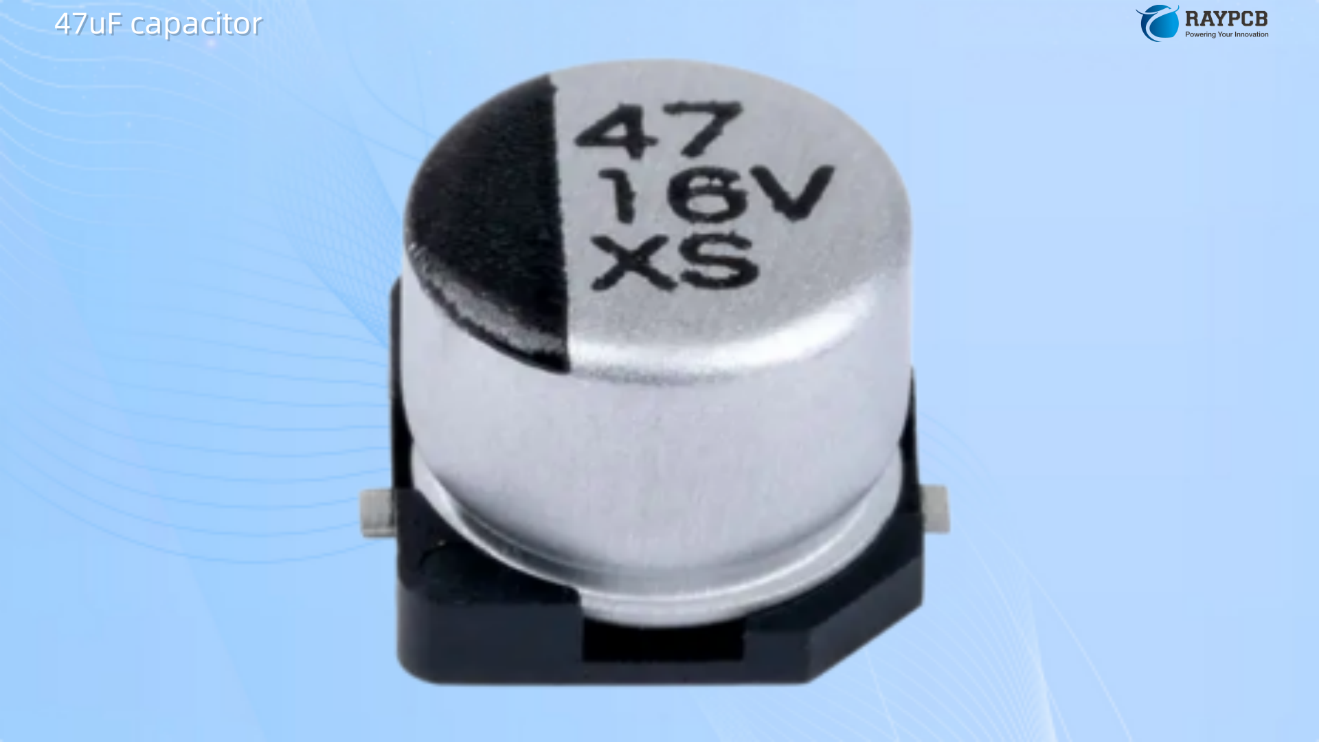
What Is a 47uF Capacitor?

A 47uF capacitor stores 47 microfarads of charge โ€” that’s 47 ร— 10โปโถ farads. It sits in a mid-range sweet spot: large enough to handle meaningful bulk energy storage and low-frequency filtering, yet small enough to appear in compact board designs without hogging real estate.

The value 47ยตF follows the standard E6/E12 capacitor series and is one of the most manufactured capacitance values globally. You’ll find it in electrolytic, tantalum, polymer, and even ceramic form factors, each with different behavior at frequency, temperature, and load.

From a PCB design standpoint, the 47uF capacitor is typically doing one of three jobs:

  • Acting as a bulk capacitorย to supply instantaneous current during transient loads
  • Serving as a filter capacitorย to reduce ripple after rectification
  • Functioning as a bypass/decoupling capย on power rails near sensitive ICs

Understanding which role it’s playing in your circuit changes how you select it, size it, and place it on the board.

How the 47uF Capacitor Works in Power Supply Filtering

The Ripple Problem in Rectified DC Supplies

When you rectify AC mains through a bridge rectifier, you don’t get clean DC โ€” you get pulsating DC with a significant ripple voltage riding on top of it. At 50Hz mains frequency, the ripple comes in at 100Hz (full-wave rectified). At 60Hz, it’s 120Hz. That ripple will show up as audible hum in audio gear, instability in voltage regulators, and noise coupling into adjacent signal traces.

A filter capacitor placed across the rectifier output charges to the peak voltage and then slowly discharges into the load between peaks, “filling in” the valleys of the waveform. The formula that governs this:

C = I ร— ฮ”t / ฮ”U

Where:

  • Cย = capacitance in farads
  • Iย = load current in amps
  • ฮ”tย = half-period of the ripple (0.01s at 50Hz, 0.0083s at 60Hz)
  • ฮ”Uย = acceptable peak-to-peak ripple voltage

For a light load โ€” say, a 20mA microcontroller supply โ€” a 47uF capacitor can keep ripple well under 100mV. For anything drawing hundreds of milliamps, you’ll need significantly more bulk capacitance, often stacking several large electrolytics in parallel.

Where the 47uF Value Fits in Filter Design

The 47uF capacitor isn’t your primary smoothing cap in a mains-fed linear supply. That job usually goes to a 1000ยตFโ€“10,000ยตF electrolytic. Where 47uF shines is as a secondary filter stage โ€” placed after a series resistor (RC filter) or an inductor (LC filter) to knock out residual ripple before it reaches sensitive loads.

A common topology on PCBs looks like this: a large bulk electrolytic at the rectifier output, followed by a small series resistance or ferrite bead, followed by a 47uF cap close to the load. The 47uF cap decouples the load’s local power rail from the main supply line, absorbing transients and providing the immediate current that the long PCB trace inductance can’t deliver fast enough.

47uF Capacitor Types: Electrolytic, Tantalum, Polymer, and Ceramic

Choosing the right construction matters as much as choosing the right capacitance value. Here’s a direct comparison across the types most commonly available at 47ยตF:

Comparison Table: 47uF Capacitor Types

TypeTypical ESRVoltage RangeFrequency ResponsePolarityBest Use Case
Aluminum Electrolytic0.1 โ€“ 5 ฮฉ6.3V โ€“ 400VLowโ€“medium freqPolarizedBulk filtering, mains supplies
Tantalum0.1 โ€“ 1 ฮฉ4V โ€“ 50VMedium freqPolarizedSpace-constrained filtering
Polymer Aluminum5 โ€“ 50 mฮฉ2.5V โ€“ 100VMediumโ€“high freqPolarizedSMPS output, VRM, motherboards
MLCC Ceramic1 โ€“ 10 mฮฉ4V โ€“ 100VVery high freqNon-polarizedHigh-frequency decoupling

Aluminum Electrolytic

The standard workhorse. Aluminum electrolytics dominate in 47uF bulk capacitance applications because they’re cheap, widely available in voltage ratings from 6.3V all the way to 400V (and higher in some series), and large enough to handle significant ripple current. The tradeoff is ESR โ€” standard aluminum caps can run from 0.1ฮฉ up to several ohms depending on quality, frequency, and temperature. High ESR directly increases output voltage ripple and generates heat inside the capacitor, accelerating electrolyte evaporation and aging.

A cheap aluminum electrolytic may only be rated for 1,000 hours at 85ยฐC. Higher-grade parts are typically rated for several thousand hours at their maximum temperature. In any design expected to run at elevated temperatures or high ripple currents, this distinction matters enormously.

Tantalum

Tantalum capacitors offer lower ESR than standard electrolytics in a smaller physical package. They’re popular in space-constrained portable designs. However, tantalum has a well-known failure mode: reverse polarity or overvoltage can cause them to fail catastrophically โ€” sometimes with fire. Always apply voltage derating (50% or more) and never reverse-bias them. A 47uF tantalum should never run at its rated voltage in a production design.

Polymer Aluminum

Polymer caps use a conductive polymer electrolyte instead of liquid electrolyte, which dramatically reduces ESR โ€” often into the milliohm range โ€” and eliminates the electrolyte dry-out failure mode. They’re the preferred choice for high-frequency SMPS designs, VRMs on motherboards, and anywhere ripple current is high. From around 2007 onward, better-quality computer motherboards migrated almost entirely to polymer capacitors for exactly this reason.

Ceramic (MLCC)

Getting a 47uF ceramic capacitor is possible in X5R or X7R dielectric, typically in 0805 or 1206 SMD packages. Ceramic caps offer the lowest ESR and ESL of any type, making them excellent for high-frequency decoupling. However, be aware of DC bias derating โ€” an X5R 47uF rated at 10V may only deliver 20โ€“30ยตF actual capacitance at 5V due to the voltage coefficient of Class 2 ceramics. Always check the DC bias curve in the datasheet.

Voltage Ratings for 47uF Capacitors

One of the most common PCB engineering mistakes is selecting a 47uF capacitor with a voltage rating that barely exceeds the operating voltage. The rule of thumb: derate by at least 1.5ร— to 2ร—.

If your rail is 12V, don’t use a 16V-rated cap. Use 25V minimum. If you’re running a 5V rail, a 10V-rated cap is marginal; 16V or 25V gives you headroom for transients, startup surges, and reliability margin.

Common 47uF Voltage Ratings

Application RailMinimum Recommended Cap Rating
3.3V logic supply10V (16V preferred)
5V logic supply16V (25V preferred)
12V power rail25V (35V or 50V preferred)
24V industrial50V (63V preferred)
Mains rectifier (120/240VAC)250V โ€“ 400V+

Exceeding the voltage rating causes dielectric breakdown, leading to leakage current, overheating, and in polarized types โ€” explosive failure. Electrolytic capacitors that have been overvoltaged will bulge, leak electrolyte, or vent through the pressure relief score on top of the can.

ESR and Its Impact on Power Supply Performance

ESR โ€” Equivalent Series Resistance โ€” is the single most important parameter after capacitance when selecting a 47uF capacitor for power supply filtering.

In an SMPS (switched-mode power supply), the output capacitor’s ESR directly contributes to output ripple voltage. Every ampere of ripple current flowing through the capacitor creates a voltage drop across the ESR. High ESR means higher ripple, more heat, and shortened component life.

In a linear power supply, ESR affects how well the capacitor can handle transient current demands โ€” a sudden load step requires the cap to deliver current immediately, and the internal resistance limits that delivery.

Low-ESR polymer and ceramic caps address this, but they introduce their own consideration: very low ESR can cause instability in some linear regulators (LDOs) that rely on a minimum ESR for phase margin in their control loop. Always check the LDO datasheet for ESR range recommendations on the output capacitor. Some LDOs specify a minimum ESR of 0.1ฮฉ to 1ฮฉ for stability โ€” a polymer cap at 10mฮฉ will not behave the same way.

Bulk Capacitance: What It Is and Why 47uF Appears So Often

“Bulk capacitance” refers to capacitors placed at the board or module level to supply instantaneous current during load transients โ€” before the power supply regulator loop can respond. Think of it as a local energy reservoir that bridges the gap between a sudden current demand and the supply’s response time.

PCB engineers place bulk caps at multiple levels of the power distribution network:

  • Board inputย โ€” large electrolytic, 470ยตFโ€“10,000ยตF, at the power entry point
  • Local supply planeย โ€” mid-size, 47ยตFโ€“220ยตF, distributed near major load zones
  • Per-IC decouplingย โ€” small ceramic, 100nFโ€“10ยตF, right at the IC power pins

The 47uF capacitor occupies the “local supply plane” tier. It’s large enough to handle millisecond-scale current demands and small enough to place in multiples across a board without layout issues. When you see a cluster of 47uF electrolytics near a processor VRM or at the input of a switching regulator, that’s exactly the role they’re serving.

PCB Layout Best Practices for 47uF Capacitors

Getting the capacitor value right is only half the battle. Poor layout kills performance regardless of component quality.

Place bulk caps close to the load. PCB trace inductance is real โ€” even a few centimeters of trace between a 47uF cap and a fast-switching IC can render the cap ineffective at the frequencies that matter. The inductance of the trace delays current delivery and can even cause resonance with the capacitor’s own ESL.

Use short, wide traces. Narrow traces add resistance and inductance. Ground returns from the capacitor should go directly to the ground plane โ€” don’t chain capacitor grounds through shared traces.

Via placement matters. If the 47uF cap is on the top layer connecting to a ground plane beneath, use at least two ground vias and place them as close to the pad as possible to minimize inductance.

Don’t rely on a single 47uF. Paralleling multiple smaller capacitors often gives better high-frequency performance than a single large cap because each cap has its own ESL, and the parallel combination lowers total inductance. However, be aware that paralleling capacitors of very different sizes can create resonance at certain frequencies โ€” a large electrolytic and a small ceramic in parallel will have an anti-resonance peak where impedance rises. Adding a small series resistance (even a short ferrite bead) between them helps damp this resonance.

For more on how capacitors interact with your PCB design, including placement strategy and design rules, it’s worth reviewing your layout against established PCB engineering guidelines before sending to fab.

Common Applications of the 47uF Capacitor

Power Supply Output Filtering

Whether it’s a 78xx linear regulator or a buck converter IC, a 47uF cap commonly appears at the output. For LDO regulators, the output cap is part of the stability network. The regulator’s datasheet will specify minimum capacitance and โ€” critically โ€” the acceptable ESR range.

SMPS Bulk Input Capacitor

At the input of a switching regulator, a 47uF cap (or several in parallel) helps supply the pulsed current demand of the switching transistor. Without adequate input capacitance, the input voltage ripple can become large enough to affect converter efficiency or trigger under-voltage lockout.

Audio Coupling and Power Filtering

In audio circuits, 47uF electrolytic capacitors serve as power supply bypass caps on op-amp rails (usually in parallel with 100nF ceramics). They handle low-frequency supply rejection while the ceramic handles HF noise. The combination covers a wider frequency span than either component alone โ€” a technique sometimes called “decade decoupling.”

Motor Driver Supplies

Small DC motor driver circuits use 47uF bulk caps to absorb the back-EMF transients that occur when motor current commutates. These applications can be punishing on capacitors due to repetitive high-current pulses, making low-ESR polymer caps or paralleled electrolytics the right choice.

How to Read a 47uF Capacitor Datasheet: Key Parameters

ParameterWhat to Look For
Capacitance47ยตF ยฑ20% (standard) or ยฑ10% (tighter grades)
Voltage RatingMust exceed max circuit voltage ร— 1.5โ€“2ร—
ESRAt 100kHz for SMPS; at 120Hz for linear supplies
Ripple CurrentRMS current rating must exceed your calculated ripple current
Temperature Rating85ยฐC standard; 105ยฐC for demanding environments
LifetimeHours at max temperature (1000h = budget; 5000h+ = quality)
Leakage CurrentRelevant for energy storage / low-power designs

Useful Resources for Engineers Working with 47uF Capacitors

Murata SimSurfing โ€” www.murata.com/en-us/tool/simsurfing: Simulate capacitor frequency response, including DC bias derating for MLCCs

TDK Product Database โ€” product.tdk.com: Comprehensive datasheets for aluminum electrolytic and MLCC lines in 47ยตF values

Panasonic Capacitor Selector โ€” industrial.panasonic.com: Useful for filtering to polymer and electrolytic parts by ESR, ripple current, and temperature rating

Nichicon Capacitor Series Catalog โ€” nichicon.co.jp/english/products/alm_elec/: Includes detailed ESR tables and ripple current ratings across temperature

ElectronicBase Smoothing Capacitor Calculator โ€” electronicbase.net/smoothing-capacitor-calculator: Quick online calculator for sizing filter capacitors by ripple and load current

Wรผrth Elektronik REDEXPERT โ€” we-online.com/redexpert: Frequency-domain impedance simulation for capacitors across their product line

Frequently Asked Questions About the 47uF Capacitor

Q1: Can I replace a 47uF capacitor with a 100uF capacitor of the same voltage rating?

In many filtering and bulk decoupling applications, yes โ€” a larger capacitor will generally reduce ripple further and provide more energy storage. The caveat is timing-sensitive circuits (such as oscillator RC networks or soft-start timing) where the capacitance value sets a specific time constant. In those cases, changing from 47uF to 100uF will directly alter circuit behavior. Always check what role the cap plays in the specific circuit before substituting.

Q2: Why does my 47uF electrolytic feel warm during operation?

Heat in a capacitor almost always traces back to high ripple current flowing through ESR. The power dissipated is P = Iยฒ ร— ESR. If you’re running a cheap electrolytic with 1ฮฉ ESR at even 100mA of ripple current, that’s 10mW of heat in a tiny package โ€” which adds up. Switching to a low-ESR polymer cap, paralleling multiple caps, or reducing ripple current through better filtering design all address this.

Q3: What is the difference between a 47uF bulk cap and a 100nF decoupling cap?

They serve different roles at different frequencies. The 47uF bulk cap handles low-frequency transients and stores meaningful energy for millisecond-scale load changes. The 100nF ceramic decoupling cap handles high-frequency switching noise right at the IC power pins, thanks to its very low ESL. Both are needed in most power distribution networks โ€” they are complementary, not interchangeable.

Q4: Why do some LDO datasheets specify minimum ESR for the output capacitor?

Many LDO regulators use the output capacitor as part of their internal compensation network. The ESR of the capacitor creates a zero in the loop transfer function that improves phase margin and prevents oscillation. If you use a very low-ESR polymer or ceramic cap where the datasheet expects a higher-ESR electrolytic, the regulator may oscillate. Always read the output capacitor section of the LDO datasheet carefully and match ESR range, not just capacitance.

Q5: Can a 47uF ceramic capacitor replace a 47uF electrolytic?

Electrically, it depends on the application. Ceramic caps have far lower ESR and ESL, which is an advantage in high-frequency switching circuits. However, 47uF ceramics in X5R/X7R exhibit significant capacitance loss under DC bias โ€” a 47uF X5R at its rated voltage may measure only 15โ€“25ยตF in circuit. This effectively changes your filter behavior. Ceramic caps are also non-polarized, which removes the polarity failure mode. For bulk filtering in linear supplies, a 47uF ceramic is overkill in cost but technically valid. For SMPS high-frequency decoupling, they’re excellent. Just always verify actual capacitance under operating bias conditions using the manufacturer’s simulation tools.

Summary

The 47uF capacitor is one of the most frequently specified values in power electronics for good reason. It bridges the gap between large bulk electrolytics and small high-frequency ceramics, making it ideal for secondary filtering, local power rail decoupling, SMPS output filtering, and audio supply bypassing. Selecting the right type โ€” electrolytic, tantalum, polymer, or ceramic โ€” depends on the ESR requirements, operating frequency, voltage, temperature environment, and the specific behavior expected by the circuit.

As a PCB engineer, the most impactful decisions around a 47uF cap aren’t just about capacitance โ€” they’re about ESR, voltage derating, ripple current handling, layout proximity to the load, and operating temperature rating. Get those right, and this unassuming component will serve your designs reliably for the life of the product.

Resources mentioned in this article are provided for engineering reference. Always verify component specifications against your specific application requirements and consult manufacturer datasheets before finalizing a design.

22uF Capacitor: Voltage Regulators, Audio & Power Rail Uses โ€” A PCB Engineer’s Guide

Learn how the 22uF capacitor works in voltage regulators, audio coupling, and PCB power rail decoupling. Covers electrolytic, tantalum, and MLCC types, ESR selection, LDO stability, and practical design tips from a PCB engineer’s perspective.

If you’ve been doing PCB layout for more than a few months, you’ve placed a 22uF capacitor so many times it’s practically muscle memory. But there’s more going on with that little component than most people stop to think about. The value sits in a practical sweet spot โ€” big enough to handle bulk decoupling and audio coupling duties, small enough that you’re not fighting board space or bill-of-materials cost. This guide breaks down what a 22uF capacitor actually does in real circuits, where to reach for one versus a different value, and how to choose the right type for your application.

What Is a 22uF Capacitor?

A 22uF capacitor stores 22 microfarads of charge โ€” that’s 22 millionths of a farad. In practical terms, it sits in the “medium bulk” category of capacitance. It’s too large for high-frequency RF bypass work (that’s where your 100nF ceramics live), but too small to serve as a main reservoir cap in a heavy-current power supply. Its sweet spot covers low-frequency filtering, audio signal coupling, LDO regulator stabilization, and power rail decoupling for moderate-current ICs.

The value also shows up constantly in reference designs and application notes from major semiconductor manufacturers โ€” it’s a de facto standard output capacitor recommendation for a huge range of LDO and switching regulators.

Types of 22uF Capacitors

Not all 22uF caps are created equal. The dielectric and package technology you choose will determine ESR, ESL, temperature stability, physical size, and cost. Here’s a quick breakdown:

TypeESRPolarized?Best ForTypical Package
Aluminum ElectrolyticMediumโ€“High (50โ€“200 mฮฉ)YesBulk decoupling, power railsRadial, SMD
TantalumLowโ€“Medium (0.1โ€“1 ฮฉ)YesLDO output, space-constrained boardsSMD Case Aโ€“D
Polymer Tantalum / AluminumVery Low (<50 mฮฉ)YesLow-noise audio, high-reliability PSUSMD
MLCC (Ceramic)Very Low (<10 mฮฉ)NoHigh-frequency decoupling, compact designs0805, 1206, 1210

Getting 22ยตF in an MLCC used to require a 1210 footprint at minimum. Modern X5R and X7R dielectrics in 0805 can now hit 22ยตF at 6.3V or 10V โ€” but watch out for voltage coefficient derating. A 22ยตF/6.3V MLCC in 0805 might drop to 8โ€“10ยตF of effective capacitance at 3.3V DC bias. Always check the de-rating curves in the datasheet before finalizing your design.

22uF Capacitor in Voltage Regulators

This is where the 22uF capacitor earns its keep most visibly. Open practically any LDO regulator datasheet โ€” AMS1117, LM1117, MIC5219, TLV755P โ€” and you’ll find a 22uF output capacitor in the typical application circuit.

Why LDOs Need an Output Capacitor

LDO regulators rely on output capacitance for loop stability. Without adequate capacitance on the output pin, the internal feedback loop can oscillate, producing noise or outright instability. The output capacitor on a linear regulator also supplies current at the regulated voltage when there’s a sudden demand from the load while the regulator attempts to compensate.

In a voltage regulator, capacitors placed at the input and output terminals filter out AC noise, suppress rapid voltage changes, and improve feedback loop characteristics โ€” and also serve as bulk energy storage, providing instantaneous current to either the input or the load.

Output Capacitor: 22uF vs Other Values

The LM1117/AMS1117 family is one of the most widely used LDO families on the planet. For the LM1117, the datasheet recommends a minimum 10ยตF tantalum output capacitor โ€” but 22ยตF, 47ยตF, or 100ยตF will also work fine. In practice, 22ยตF strikes the best balance: it provides adequate phase margin, keeps transient response tight, and won’t cause instability issues if you accidentally grab a low-ESR polymer type.

ESR: The Hidden Variable

Multilayer ceramic capacitors combine small size, low ESR, low ESL, and wide operating temperature range, making them a first-choice option for bypass capacitors โ€” but their capacitance can vary dramatically with temperature, DC bias, and AC signal level. For LDO output capacitors that specify a minimum ESR for stability, using a pure MLCC without additional series resistance can push the regulator into oscillation. Classic LDOs like the LM317 can behave unexpectedly with very low-ESR capacitors at the output.

As an example, a 22uF output capacitor on an LM317 effectively bypasses the regulator at higher frequencies โ€” but since the LM317 is inductive in those regions, this makes for a resonant circuit, and some damping in the form of a not-too-low capacitor ESR is required. Using a 220ยตF/10mฮฉ cap at the output can create a massive resonant peak. This is exactly why many engineers keep a tantalum or polymer cap at the LDO output rather than going straight MLCC.

Adjust Pin Bypass (LM317/LM337)

Bypassing the adjustment pin of an LM317 with a 22ยตF capacitor reduces output noise by approximately 20dB โ€” a substantial improvement, particularly for audio power supply rails. If you’re building a linear supply for a preamp or DAC board, this is a mandatory step.

22uF Capacitor in Audio Circuits

Audio applications are one of the most demanding environments for any passive component. Signal integrity, low noise, and predictable frequency response all depend on choosing the right capacitor โ€” and the 22ยตF value appears repeatedly in audio design for two main jobs.

DC Blocking / Signal Coupling

In signal processing, 22ยตF capacitors can block DC signals and allow AC signals to pass โ€” this is crucial in audio circuits where you need to separate signal components, and the value is commonly used in amplifiers, mixers, and preamplifiers.

In practice, a 22ยตF coupling cap into an 8kฮฉ input impedance gives you a -3dB low-frequency rolloff around 0.9Hz โ€” well below audible range. That’s why you see 22ยตF so often at the output stage of op-amps and buffer circuits feeding headphone jacks or line outputs. It passes the full audio band while blocking any DC offset that could damage downstream components or produce an ugly “pop” when a device powers up.

Power Supply Filtering for Audio Rails

A clean power rail is non-negotiable in audio work. Digital hash from microcontrollers and switching converters has to be kept off the analog supply. A 22ยตF bulk cap in parallel with a 100nF ceramic handles a broad frequency range: the 22ยตF covers sub-100kHz ripple, and the ceramic handles the high-frequency garbage the electrolytic can’t see due to its parasitic inductance.

ApplicationRecommended CapNotes
LDO adjust pin bypass (LM317)22ยตF electrolyticReduces noise ~20dB
LDO output stabilization22ยตF tantalum or polymerCheck min ESR in datasheet
Audio output coupling22ยตF bipolar electrolyticNon-polarized type for AC signal paths
Power rail bulk decoupling22ยตF + 100nF in parallelCovers broad frequency range
DC-DC converter output22ยตF MLCC (X5R/X7R)Verify de-rating at operating voltage

Power Rail Decoupling with a 22uF Capacitor

Beyond linear regulators, the 22ยตF cap shows up heavily in power rail decoupling for digital and mixed-signal ICs. FPGAs, microcontrollers, and DSPs often call for 10โ€“22ยตF bulk caps near the power supply pins alongside smaller 100nF locals.

22ยตF capacitors employed as decoupling capacitors are placed close to integrated circuits to prevent noise and voltage drops on the power rails, ensuring components operate reliably.

Placement Matters on the PCB

As a PCB engineer, you already know that component placement is half the battle. A 22ยตF cap sitting 50mm from the IC it’s supposed to decouple is essentially useless at frequencies above a few hundred kHz. The inductance of the trace path kills its effectiveness. Place your bulk 22ยตF cap within 5โ€“10mm of the power pin, and pair it with a 100nF MLCC as close as physically possible to the pin itself.

For information on how capacitors interact with PCB layout at a design level โ€” including placement strategies and via stitching โ€” that’s worth reading before you finalize your layer stackup.

How to Select the Right 22uF Capacitor

Use this checklist before placing your order:

1. Voltage Rating โ€” Always derate by at least 50%. A 5V rail needs a cap rated for at least 10V. This is especially critical for ceramics, which experience significant capacitance loss with applied voltage.

2. ESR Requirements โ€” Check whether your regulator requires a minimum ESR for stability. Old-school bipolar LDOs often do. Modern CMOS LDOs are often designed to work with ceramics.

3. Temperature Range โ€” Industrial designs need -40ยฐC to +85ยฐC at minimum. Automotive goes to +125ยฐC. Aluminum electrolytics lose capacitance in cold and dry out over time in high temperatures.

4. Package / Footprint โ€” SMD polymer or tantalum for space-constrained boards. Through-hole electrolytic for prototyping or high-voltage rails where SMD options get large and expensive.

5. Polarized vs Non-Polarized โ€” In AC signal paths (coupling caps), use bipolar electrolytics or film capacitors. In DC power paths, standard polarized electrolytics are fine โ€” just never reverse them.

Common 22uF Capacitor Voltage Ratings

Voltage RatingTypical Use Case
6.3VLow-voltage digital rails (3.3V, 1.8V) โ€” check de-rating
10V5V digital logic rails
16V12V rails with margin
25VGeneral-purpose audio and power supply use
50VHigher-voltage rails, automotive

Useful Resources for Engineers

  • DigiKey 22ยตF Capacitor Parametric Searchย โ€” digikey.comย โ€” Filter by capacitance, voltage, ESR, and package. Includes manufacturer datasheets.
  • Mouser Electronicsย โ€” mouser.comย โ€” Cross-reference tool for substituting capacitors by specification.
  • Analog Devices Application Note: “Why the Choice of Bypass Capacitor Matters”ย โ€” Detailed analysis of ESR, ESL, and dielectric effects.
  • TI LM317 Datasheetย โ€” Includes adjustment pin bypass recommendations and output cap guidelines.
  • AMS1117 Datasheetย โ€” One of the most widely copied LDO reference designs; output cap section is essential reading.
  • Murata SimSurfingย โ€” product.murata.com/simsurfingย โ€” Simulate MLCC capacitance de-rating versus DC bias and temperature interactively.
  • KEMET SPICE Modelsย โ€” Downloadable SPICE models for tantalum and polymer capacitors, useful for LTspice stability simulation.

Frequently Asked Questions

Q1: Can I substitute a 22ยตF capacitor with a 10ยตF or 47ยตF?

It depends on the application. For LDO output caps, going larger (47ยตF) is usually fine and often improves transient response. Going smaller (10ยตF) may work but could compromise stability or ripple rejection. Always verify against the datasheet minimum. For audio coupling, changing the value shifts the low-frequency rolloff point, so the choice has a direct audible impact.

Q2: Why does my MLCC 22ยตF cap measure only 8โ€“10ยตF on my LCR meter?

This is normal. X5R and X7R MLCCs experience significant capacitance reduction under DC bias. A 22ยตF/6.3V cap measured at 3.3V DC may show an effective value well below the labeled rating. This is called voltage coefficient degradation, and it’s why the datasheet de-rating curves matter. If you need a stable 22ยตF, use a tantalum or polymer type.

Q3: Do I need a 22ยตF at both the input and output of an LDO?

Most modern LDOs only mandate an output cap for stability. An input cap (typically 1โ€“10ยตF) is recommended if the regulator is more than a few centimeters from the main supply capacitor โ€” it protects against load transients traveling backward into the input pin. Check your specific IC’s datasheet, as requirements vary significantly.

Q4: Is a 22ยตF capacitor polarized?

It depends on the type. Aluminum electrolytic and tantalum types are polarized โ€” connect them backwards and you risk damage or failure, sometimes dramatically. MLCC ceramic capacitors are never polarized. Bipolar (non-polarized) electrolytic 22ยตF caps exist specifically for AC audio coupling applications.

Q5: Can a 22ยตF capacitor be used in an RC timing circuit?

Yes, and it’s a common choice. With a 720ฮฉ resistor, a 22ยตF cap gives an RC time constant of roughly 15.8ms โ€” useful for debounce circuits, LED fade effects, or reset delay networks in microcontroller designs. The formula is simply ฯ„ = R ร— C.

The 22uF capacitor isn’t glamorous, but it’s one of those components that quietly holds a lot of designs together. Whether you’re stabilizing an LDO, blocking DC from an audio output, or anchoring a power rail against transient spikes, getting the type and placement right makes a real difference in circuit performance. The next time you drop one on a schematic, you’ll know exactly why it’s there.

10F to 100F Supercapacitors: Energy Storage, IoT & Backup Power

A PCB engineer’s complete guide to 10F supercapacitors โ€” covers energy storage calculations, IoT pulse power, backup hold-up sizing, series balancing, charging circuit design, and PCB layout tips. Includes worked examples, comparison tables, and brand selection guide.

Ask a PCB engineer when they first seriously looked at supercapacitors and most will point to a specific frustrating moment โ€” a battery-backed SRAM that kept losing data on power-down, a GPS tracker that failed in its third year due to pulse-induced battery fatigue, or an industrial meter that bricked itself because the transmit pulse collapsed the supply voltage. The 10F supercapacitor โ€” and its siblings up to 100F โ€” solve a very specific class of problems that neither electrolytics nor lithium cells handle well: high-current short-duration bursts, maintenance-free backup power, and decade-long operation without chemical degradation.

This guide covers how 10F to 100F supercapacitors work, where they fit in real circuit designs, how to charge and balance them correctly, and how to decide when a supercapacitor is the right answer and when it isn’t.

What Is a 10F Supercapacitor and How Does It Store Energy?

A supercapacitor โ€” also called an ultracapacitor or electric double-layer capacitor (EDLC) โ€” stores energy electrostatically at the interface between an electrode and an electrolytic solution rather than in a chemical reaction like a battery. Two porous carbon electrodes are separated by an electrolyte and a separator. When voltage is applied, ions from the electrolyte accumulate on the electrode surfaces, forming an electric double layer on each electrode. This double layer acts as the capacitor, enabling rapid charge and discharge with virtually no degradation over time.

Supercapacitors store 10 to 100 times more energy per unit volume or mass than electrolytic capacitors, can accept and deliver charge much faster than batteries, and tolerate many more charge and discharge cycles than rechargeable batteries.

A 10F supercapacitor at 2.7V stores: E = ยฝ ร— 10 ร— 2.7ยฒ = 36.45 joules. Compare that to a 10,000ยตF electrolytic at 50V which stores 12.5 joules โ€” the supercapacitor at a fraction of the voltage and physical size stores nearly three times the energy. At 100F, you have 364.5 joules available. That is real, usable backup energy for embedded systems.

Supercapacitor vs Battery vs Electrolytic: Knowing Where Each Belongs

This comparison comes up constantly in design reviews, and the honest answer is that these technologies rarely compete โ€” they occupy different performance envelopes.

ParameterElectrolytic Cap10F SupercapacitorLi-Ion Battery
Capacitance10ยตF โ€“ 10,000ยตF0.1F โ€“ 3,000FN/A
Energy DensityVery LowMediumHigh
Power DensityMediumVery HighMedium
Charge TimeMillisecondsSeconds โ€“ Minutes1โ€“4 Hours
Cycle LifeN/A (passive)500,000 โ€“ 1,000,000300โ€“1,500
Temperature Range-40ยฐC to +105ยฐC-40ยฐC to +70ยฐC-20ยฐC to +60ยฐC
Self-DischargeNegligibleHigh (weeks)Low (months)
Failure ModeElectrolyte dry-outGradual capacity lossThermal runaway risk
Lifespan5โ€“15 years (derated)10โ€“20+ years2โ€“5 years

Supercapacitors provide small form factor storage that last 2โ€“4 times longer than batteries with high power density and no thermal runaway risk. That last point matters increasingly in industrial and medical applications where battery thermal events are a serious regulatory and safety concern.

The critical limitation to understand upfront: a supercapacitor’s voltage is not flat during discharge. Unlike a battery that holds near-constant voltage until it depletes, a supercapacitor’s terminal voltage falls linearly as it discharges. A 10F cap discharged from 2.7V to 1.35V delivers only half its stored energy, and your downstream circuit must tolerate this voltage slope or include a boost converter to regulate from the falling input.

Real-World Applications for 10F to 100F Supercapacitors

IoT Pulse Power and Battery Protection

This is arguably the most important application for 10F supercapacitors in 2025 and beyond. Standard Li-SOClโ‚‚ batteries offer phenomenal energy density and a long shelf life due to their passivation layer. However, when the meter suddenly requires a 2-amp pulse to transmit daily usage data via a 5G or NB-IoT network, the passivation layer causes a severe voltage delay. This voltage drop can cause the meter’s microprocessor to reboot, leading to lost data and field failures.

The solution is to pair the battery with a 10F supercapacitor. The supercapacitor handles the 2A transmission burst; the battery trickle-charges it between events. The result is a system that achieves decade-long operational life without maintenance โ€” something neither technology achieves independently. Factory testing proves that the failure rate of non-hybrid trackers jumps by 40% in year three due to pulse-induced battery fatigue. By absorbing the high-current demands, the hybrid capacitor dramatically reduces the strain on the primary cell.

SRAM and RTC Backup Power (10Fโ€“50F)

One of the oldest and most reliable uses of small supercapacitors is backing up real-time clocks and SRAM in embedded systems during power loss. A 10F supercapacitor charged to 3.3V can power an RTC drawing 1ยตA for: t = C ร— ฮ”V / I = 10 ร— (3.3 โ€“ 2.0) / 0.000001 = 13 million seconds โ€” roughly 150 days. Even accounting for self-discharge, that is effective backup for any plausible power outage scenario. This replaces a coin cell battery entirely in many designs, removing the maintenance burden and the battery-related regulatory requirements around disposal.

Industrial Hold-Up and Graceful Shutdown (50Fโ€“100F)

In industrial automation and data acquisition systems, an unexpected power loss can cause data corruption, valve misalignment, or mechanical damage if the CPU doesn’t execute a proper shutdown sequence. Key applications include pulse power, ride-through power, graceful shutdown, hybrid energy storage systems (HESS) and backup power.

A 100F supercapacitor at 5V stores 1,250J โ€” enough to power a 500mA microcontroller-based system for 2,500 seconds (over 40 minutes) before the voltage drops to 0V, or more realistically, several minutes of clean operation above the 3.3V minimum supply threshold. For a graceful shutdown that only needs 200ms of hold-up, even a 10F cap is massively over-specified โ€” which is exactly the kind of comfortable engineering margin that makes products reliable in the field.

Energy Harvesting Power Management

IoT devices for various sensing and monitoring applications, particularly systems deployed to monitor pollution or ecosystem parameters, have a need for self-sustaining energy sources. In these cases, modern supercapacitor families can be used to replace batteries, which can rely on lower levels of energy harvesting to become self-sustaining fit-and-forget devices.

In solar-harvested remote sensor nodes, a 10Fโ€“50F supercapacitor buffers the harvested energy across multiple charge-discharge cycles per day without any degradation in capacity. Over a ten-year deployment, the supercapacitor will still perform at close to rated capacity while any battery in the same role would have needed replacement two or three times.

How to Calculate the Right Supercapacitor Capacity

The sizing formula depends on your application type.

For Backup / Hold-Up Applications

C = I ร— t / ฮ”V

Where I is the load current in amps, t is the required hold-up time in seconds, and ฮ”V is the usable voltage swing (rated voltage minus minimum operating voltage of the load).

Example: Hold-up for a 100mA system, 5 seconds, operating from 5V down to 3.0V: C = 0.1 ร— 5 / (5.0 โ€“ 3.0) = 0.25F minimum

A 1F coin cell supercapacitor handles this with significant margin. For a 60-second hold-up at the same current: C = 0.1 ร— 60 / 2 = 3F minimum โ€” now you need a 10F cylindrical supercapacitor.

For Pulse Power / Transmission Bursts

C = I_pulse ร— t_pulse / ฮ”V_allowed

Example: 2A LoRa transmission pulse for 50ms, maximum 200mV supply droop on a 3.3V rail: C = 2 ร— 0.05 / 0.2 = 0.5F minimum

Again, a 10F supercapacitor provides 20ร— margin โ€” sensible given that the supercapacitor is protecting a battery that has to last a decade.

ApplicationLoad CurrentRequired DurationRecommended Capacity
RTC backup1โ€“5 ยตAWeeks0.1F โ€“ 1F (coin type)
MCU + SRAM backup10โ€“50 mAMinutes1F โ€“ 10F
NB-IoT / LoRa pulse buffer0.5โ€“2A50โ€“500ms1F โ€“ 10F
Graceful shutdown100โ€“500 mA1โ€“10 seconds5F โ€“ 50F
Industrial hold-up500mAโ€“2A10โ€“60 seconds50F โ€“ 100F
Motor soft-start buffer5โ€“20A100โ€“500ms10F โ€“ 100F

10F Supercapacitor Voltage Ratings and Series Connections

Most commercial cylindrical supercapacitors โ€” including 10F, 25F, 50F, and 100F sizes โ€” are rated at 2.5V or 2.7V per cell. This is a hard limit, not a guideline. Exceeding the rated cell voltage accelerates electrolyte decomposition and shortens lifespan dramatically.

For 5V systems, you need two cells in series, giving 5.4V maximum with matched cells. For 3.3V systems, a single 2.7V cell works with a simple boost/buck converter or a direct connection if your minimum voltage tolerance is acceptable.

Cell Balancing for Series-Connected Supercapacitors

When multiple supercapacitors are connected in series to achieve higher voltage ratings, charge imbalances can occur due to manufacturing tolerances and differences in self-discharge rates. Uneven charge distribution among the supercapacitors can lead to overvoltage stress on individual cells, reducing their lifespan and potentially causing failure.

Cell balancing in series-connected capacitors ensures that the voltage across each cell is approximately equal; a lack of cell balancing in a supercapacitor may lead to overvoltage damage. Supercapacitor capacitance can vary up to ยฑ20% of the rated value due to manufacturing variance and aging โ€” this variance means without balancing, the cell with lower capacitance will reach its voltage limit first.

Two balancing approaches are used in practice:

Passive balancing uses a resistor in parallel with each cell to dissipate excess charge and equalize voltage. Simple and cheap, but continuously wastes a small amount of current. Resistor value is typically set so the balancing current is 3โ€“10ร— the self-discharge current of the supercapacitor โ€” around 1โ€“10mฮฉ for a 10F cell.

Active balancing uses dedicated ICs such as the Texas Instruments bq33100 or the Linear Technology LTC3128 to shuttle charge between cells efficiently. Active balancing efficiently shuttles charge between the capacitors, eliminating the power losses and required subsequent recharge cycles with dissipative methods. The cost and complexity are higher, but for systems that need maximum energy availability over long hold-up periods, active balancing delivers better performance.

Charging Circuit Design for 10F Supercapacitors

To charge a supercapacitor efficiently and safely, a proper charging circuit is required. The key difference from charging a battery is that a supercapacitor’s terminal voltage rises linearly as it charges โ€” there is no absorption phase, no chemistry to monitor. This makes the control logic simpler in principle, but inrush current management is mandatory.

A discharged 10F supercapacitor presents a near-dead short at power-up. If you connect a 5V supply directly to a discharged 10F cap through a 1ฮฉ series resistor, the initial inrush current is 5A. Without current limiting, you will stress the supply, the protection diodes, and potentially damage the supercapacitor itself if inrush is severe enough.

The three standard approaches:

Series Resistor โ€” simplest, cheapest. A 10ฮฉ resistor limits inrush to 500mA from a 5V supply. Charge time to 90% is roughly 5 ร— RC = 5 ร— 10 ร— 10 = 500 seconds. Too slow for most applications if the resistor is left in series permanently.

Current-Limited Charger IC โ€” the right call for most designs. The LTC3128 (Linear/Analog Devices), TI bq33100, and similar dedicated supercapacitor charger ICs provide programmable constant-current charging with overvoltage protection. A buck-boost IC supercapacitor charging solution needs to possess flexibility โ€” it must operate efficiently in step-up or step-down modes and can perform active charge balancing with programmable maximum capacitor voltage.

Charge-then-Bypass โ€” a resistor limits inrush until the capacitor reaches operating voltage, then a FET or relay shorts the resistor for normal operation. More hardware complexity, but gives fast charge time and zero series resistance during operation.

PCB Layout Considerations for Supercapacitors

Physically, a 10Fโ€“100F supercapacitor is a substantial component โ€” typically 35โ€“60mm tall in a 18โ€“35mm cylindrical case. Unlike an electrolytic where the capacitance label is the main design variable, placing a supercapacitor correctly on a PCB involves several additional factors.

How capacitors interact with PCB layout at the trace, via, and ground plane level determines whether the supercapacitor can deliver its rated current when it matters most. For supercapacitor applications, these are the layout rules that actually matter in production:

High-current discharge paths must be wide and short. A 10F supercapacitor can deliver tens of amps in a short-circuit scenario. Even in normal operation, a 2A pulse discharge demands traces wide enough to carry current without significant resistive loss or heating. Minimum 3mm trace width for 2A on 1oz copper.

Use through-hole or snap-in footprints for physical stability. Large supercapacitors experience significant mechanical stress during vibration. SMD supercapacitors exist for smaller values but cylindrical 10Fโ€“100F types should be through-hole or provided with a PCB-mounted clamp.

Keep the supercapacitor away from heat sources. Operating temperature directly affects both self-discharge rate and long-term capacity retention. Every 10ยฐC of unnecessary heat shortens effective lifespan. Keep reservoir supercapacitors away from power FETs, bridge rectifiers, and transformer cores.

Never omit polarity markings on the silkscreen. Supercapacitors are polarized. Reversing polarity even briefly is destructive and potentially hazardous. Mark polarity explicitly in the silkscreen, include a mechanical key in the footprint if possible, and double-check orientation in the PCB review.

Leading 10F to 100F Supercapacitor Series by Application

BrandSeriesCapacitance RangeVoltageBest Application
EatonPowerStor HV1F โ€“ 50F2.7Vโ€“5.5VIoT, backup, broad portfolio
MurataSCBS series0.1F โ€“ 10F2.3Vโ€“5.5VSMD, wearables, IoT
Maxwell (Vishay)K2 Series350F โ€“ 3,000F2.7VModule-level industrial
NichiconJJD / JJE Series0.1F โ€“ 50F2.7Vโ€“5.5VIndustrial, automotive
PanasonicGold Cap0.1F โ€“ 70F2.3Vโ€“5.5VRTC backup, embedded systems
Cornell DubilierDSF / DGH1F โ€“ 100F2.7VHigh-reliability industrial
ElnaDynacap0.047F โ€“ 47F2.7Vโ€“5.5VConsumer electronics, IoT

Useful Resources for Engineers

Bookmark these references before starting any supercapacitor design:

  • Eaton Supercapacitor Application Guidelines PDFย โ€” eaton.comย โ€” Covers sizing calculations, ESR/capacitive discharge, series connection, and PCB soldering guidelines. Start here.
  • Texas Instruments bq33100 Datasheetย โ€” ti.comย โ€” Single-chip supercapacitor management with balancing, monitoring, and protection for up to 5 cells in series.
  • Analog Devices LTC3128 Datasheetย โ€” analog.comย โ€” Buck-boost supercapacitor charger with active balancing and programmable current limit. Excellent for 2-cell series designs.
  • Panasonic Gold Cap Selection Guideย โ€” industrial.panasonic.comย โ€” Full parametric tables including self-discharge rates, temperature derating, and lifetime projection charts.
  • Skeleton Technologies Supercapacitors 101ย โ€” skeletontech.comย โ€” Clear, technically accurate introduction to supercapacitor operating principles and application segmentation.
  • DigiKey Supercapacitor Parametric Searchย โ€” digikey.comย โ€” Filter by capacitance (use “Super Capacitors” category), voltage, ESR, package, and temperature range across all major suppliers.
  • Cornell Dubilier Supercapacitor Technical Guideย โ€” cde.comย โ€” In-depth treatment of EDLC construction, ESR behavior, self-discharge characterization, and series/parallel configuration rules.
  • Electronics Weekly: Designing a Supercapacitor Charger with Balancingย โ€” electronicsweekly.comย โ€” Practical balancing circuit design considerations with passive vs active comparison and IC recommendations.

Frequently Asked Questions

Q1: Can a 10F supercapacitor replace a battery in an IoT device?

For long-term energy storage, no โ€” not with current technology. A 10F supercapacitor at 2.7V stores around 36J. A CR2032 coin cell battery stores approximately 2,500J. For powering a device through days or weeks of operation, the supercapacitor simply doesn’t hold enough energy. However, for protecting a primary battery from pulse-induced stress, providing backup power for seconds to minutes, or replacing a coin cell RTC backup in a continuously-powered system, the 10F supercapacitor is the better engineering choice. The two technologies complement rather than replace each other.

Q2: Why does my supercapacitor discharge so quickly when not in use?

High self-discharge is a known characteristic of supercapacitors compared to batteries. A 10F supercapacitor may lose 50% of its charge within a few days to weeks at room temperature depending on type and age. The energy density of supercapacitors, while impressive in terms of power delivery, typically falls short compared to traditional batteries. For applications requiring energy storage over weeks or months without recharging, a battery is the appropriate technology. For applications that are recharged frequently or where hold-up time is measured in minutes, self-discharge is a minor concern.

Q3: What happens if I exceed the 2.7V voltage rating on a supercapacitor cell?

Exceeding the rated cell voltage accelerates electrolyte decomposition and gas generation inside the cell. This degrades capacitance and increases ESR โ€” initially gradually, then catastrophically. Long-term overvoltage by even 100โ€“200mV can reduce a supercapacitor’s lifespan from 500,000 cycles to a few thousand. Always use a dedicated charger IC or voltage clamping circuit rather than relying on a fixed voltage divider with loose tolerance components to control the charge voltage.

Q4: Do I need to balance two 10F supercapacitors connected in series?

Yes, for anything beyond a prototype. Manufacturing tolerances mean two supposedly identical cells may differ by up to ยฑ20% in actual capacitance. During charging at constant current, the capacitor that reaches first the rated voltage level could be damaged in a further charging process. At minimum, add passive balancing resistors in parallel with each cell. For precision applications, use an active balancing IC. Never run series supercapacitors without some form of voltage equalization in a production design.

Q5: How long will a 10F supercapacitor last in a real product?

Supercapacitors can achieve a cycle life as high as 1,000,000 cycles. In practical terms, a supercapacitor in an IoT device that charges and discharges once per hour achieves 8,760 cycles per year โ€” reaching one million cycles after 114 years of operation. Lifespan is therefore dominated by calendar aging (electrolyte dry-out) and temperature rather than cycle count. At 25ยฐC and 2.5V operating voltage (derated from 2.7V), most quality supercapacitors are rated for 10+ years of operational life. Operating at maximum rated voltage and 70ยฐC ambient will compress that to 2โ€“3 years. Derate voltage by 10% and keep the component cool, and you will likely outlast the rest of the product.

The 10F supercapacitor occupies a design space that electrolytics can’t reach and batteries handle poorly โ€” high-current short-duration bursts, maintenance-free decade-long deployments, and clean non-chemical backup power for embedded systems. Sized correctly, charged with appropriate current limiting, balanced when in series, and placed thoughtfully on the PCB, a supercapacitor in the 10F to 100F range is one of the most reliable passive components you can put into a product. The key is matching the technology to the application โ€” and understanding clearly what a supercapacitor is designed to do well, versus where a battery remains the right answer.

1 Farad Supercapacitor: The Entry Point for Energy Storage

Discover how a 1 farad capacitor powers RTC backup, MCU hold-up, and pulse loads. Includes energy formulas, ESR specs, PCB layout tips, and manufacturer table.

Most engineers spend their careers working in the microfarad range โ€” 100 ยตF here, 470 ยตF there. Then a project comes along that needs to keep a microcontroller alive through a 500ms power interruption, or provide a burst of current to a GPS module during acquisition, and suddenly a 1 farad capacitor enters the conversation. That number stops people. One full farad. Not microfarads. Not millifarads. A farad โ€” the same unit that defines the base SI measure of capacitance, and a value that would have required a capacitor the size of a car using conventional electrolytic technology just decades ago.

Today, a 1F supercapacitor fits in a package roughly the size of a AA battery, costs under two dollars in quantity, and opens the door to a category of energy storage that sits between conventional capacitors and rechargeable batteries. Understanding where this component fits โ€” and where it doesn’t โ€” is what separates designs that work from ones that look good on paper and fall apart in the field.

What Is a 1 Farad Capacitor and How Does It Differ from Regular Capacitors?

A 1 farad capacitor is not simply a scaled-up electrolytic. It belongs to a fundamentally different component family: the electrochemical double-layer capacitor (EDLC), also called a supercapacitor or ultracapacitor. The operating principle is different, the energy storage mechanism is different, and the design implications are different.

In a conventional aluminum electrolytic capacitor, charge is stored in a thin aluminum oxide dielectric layer. In a supercapacitor, there is no dielectric in the traditional sense. Instead, charge accumulates at the interface between a high-surface-area electrode (typically activated carbon) and an electrolyte solution โ€” an effect called electrostatic double-layer capacitance. Because the electrode surface area is measured in hundreds to thousands of square meters per gram, capacitance values that would be physically impossible with dielectric technology become routine.

Supercapacitor vs. Battery vs. Electrolytic Capacitor

PropertyElectrolytic Cap1F SupercapacitorLi-Ion Battery
CapacitanceยตF range1F โ€“ 3000FN/A (Wh rated)
Energy DensityVery lowMedium-lowHigh
Power DensityVery highHighMedium
Charge/Discharge CyclesUnlimited100,000 โ€“ 1,000,000+300 โ€“ 2,000
Charge TimeMicrosecondsSeconds to minutesMinutes to hours
Self-DischargeNegligibleModerate (weeks)Low (months)
Voltage RangeFixed (stable)Varies with charge stateRelatively flat
Temperature Rangeโ€“40ยฐC to +105ยฐCโ€“40ยฐC to +65/85ยฐCโ€“20ยฐC to +60ยฐC
Cost per FaradHighVery lowN/A

The key insight is that supercapacitors don’t replace batteries and they don’t replace bypass capacitors. They occupy a specific niche: applications that need energy delivery over seconds or minutes, with very long cycle life and the ability to charge and discharge repeatedly without degradation.

Key Specifications of a 1 Farad Supercapacitor

When you open the datasheet for a 1F supercapacitor, the numbers you need to understand are quite different from what you’d look at for a standard electrolytic. Here’s what actually matters in a real design:

ParameterTypical Value (1F EDLC)Engineering Notes
Rated Capacitance1.0 F ยฑ20%Measured at low frequency, DC bias applied
Rated Voltage2.5V โ€“ 5.5VMost common: 2.7V, 5.0V, 5.5V
ESR (DC internal resistance)80 โ€“ 400 mฮฉLimits peak current delivery
Max Continuous Current0.5 โ€“ 2.0 AThermal limitation
Leakage Current1 โ€“ 10 ยตAAfter 30 min at rated voltage
Operating Temperatureโ€“40ยฐC to +65ยฐC or +85ยฐCAffects capacity and ESR
Shelf Life10 years (stored uncharged)Stored at recommended voltage
Cycle Life> 500,000 cyclesAt rated conditions
Physical Sizeร˜8โ€“16mm coin / radialVoltage rating affects size significantly

Voltage Rating: The Most Critical Parameter

Unlike a battery that maintains a relatively flat voltage during discharge, a supercapacitor’s terminal voltage is directly proportional to its state of charge. A 1F capacitor charged to 2.7V that discharges to 1.35V has delivered exactly half its stored energy. This is not optional knowledge โ€” it fundamentally determines whether your circuit will function throughout the discharge cycle.

The stored energy in a 1 farad capacitor at rated voltage is:

E = ยฝ ร— C ร— Vยฒ

At 2.7V: E = ยฝ ร— 1 ร— 2.7ยฒ = 3.645 joules

At 5.5V (series pair or higher-rated device): E = ยฝ ร— 1 ร— 5.5ยฒ = 15.1 joules

And the usable energy โ€” from V_max to V_min โ€” is:

E_usable = ยฝ ร— C ร— (V_maxยฒ โ€“ V_minยฒ)

If your circuit requires minimum 1.8V and you start at 2.7V:

E_usable = ยฝ ร— 1 ร— (2.7ยฒ โ€“ 1.8ยฒ) = ยฝ ร— (7.29 โ€“ 3.24) = 2.025 joules

These joule-level energy figures put 1F supercapacitors in a clear application space: short-duration backup, pulse energy delivery, and real-time clock (RTC) maintenance โ€” not multi-minute holdups or sustained load supply.

Practical Applications of the 1 Farad Capacitor

Real-Time Clock and SRAM Backup

This is probably the single most common application of a 1F supercapacitor in commercial electronics. Many microcontrollers and processors have an RTC subsystem and battery-backed SRAM that draws only 1โ€“10 ยตA when the main supply is removed. A 1F capacitor at 3V can supply 1 ยตA for:

t = C ร— ฮ”V / I = 1 ร— (3.0 โ€“ 1.8) / 0.000001 = 1,200,000 seconds โ‰ˆ 13.9 days

That’s nearly two weeks of RTC backup from a single 1F supercapacitor, with no battery to replace, no disposal concerns, and essentially unlimited cycle life. This is why you see supercapacitors replacing coin cells in industrial controllers, smart meters, and building automation equipment where maintenance access is limited.

Microcontroller Hold-Up During Power Interruption

A microcontroller performing a write to non-volatile memory at the moment of power loss can corrupt data or lose critical state. A 1F supercapacitor, pre-charged to the rail voltage, can power a low-power MCU (drawing say 5โ€“20 mA at 3.3V) long enough to complete the write and shut down gracefully:

At 10 mA load, from 3.3V to 2.0V:

t = C ร— ฮ”V / I = 1 ร— 1.3 / 0.010 = 130 seconds

That’s over two minutes โ€” far more than the 50โ€“500 ms that most graceful shutdown routines require.

Pulse Power for Wireless Transmission

GSM, LoRa, and other wireless modules can demand peak currents of 1โ€“2A during transmission bursts, far exceeding what a coin cell or thin battery can supply without heavy voltage droop. A 1F supercapacitor in parallel with the power source absorbs these transients and provides the burst current locally, allowing a smaller, cheaper primary supply to run the system between transmissions.

Energy Harvesting Buffer

In solar and thermoelectric harvesting systems that generate irregular, low-average-power energy, a 1F supercapacitor can buffer the harvested energy and release it in controlled bursts when the application needs it. The unlimited cycle life is especially valuable here โ€” a solar-powered sensor node that charges and discharges its energy buffer thousands of times per year would destroy a lithium battery in months but leaves a supercapacitor unaffected after years of operation.

Automotive and Industrial Memory Backup

In automotive EEPROM, instrument cluster, and infotainment systems, supercapacitors maintain voltage to memory circuits during ignition switch-off transients. The 1F value is common in lower-power systems; larger modules use stacked or higher-capacitance devices.

PCB Design Considerations for 1F Supercapacitors

Placing a capacitor on a PCB that stores joules rather than millijoules demands a different level of design care. Here’s what experienced engineers pay attention to:

Inrush Current Limiting

When you first apply power to a discharged supercapacitor, it looks like a near short-circuit. The initial charge current is limited only by ESR and the impedance of your source. A 1F cap with 200 mฮฉ ESR connected to a 5V rail can draw 25A instantaneously. This will trip current-limited supplies, damage thin PCB traces, and stress the source.

The solution is a series inrush limiting resistor โ€” typically 10โ€“100ฮฉ โ€” during initial charge. Once charged, this resistor can be bypassed with a FET or left in circuit if the IR drop is acceptable for your application. Purpose-built supercapacitor charger ICs (like the Texas Instruments TPS61225 or Maxim MAX38888) handle this automatically with controlled current ramp-up.

Polarity and Voltage Clamping

Supercapacitors are polarized. Reversing polarity, even briefly, can permanently damage the device. On a PCB where reverse polarity events are possible (automotive environments, field-replaceable modules), a protection diode or FET-based protection circuit is not optional.

Additionally, do not exceed the rated voltage. A 2.7V-rated device connected to a 3.3V rail without a voltage clamp will degrade rapidly. A simple Zener or a dedicated voltage clamp circuit keeps the supercapacitor within its safe operating area.

Self-Discharge and Leakage

Supercapacitors have significantly higher self-discharge than batteries. A charged 1F supercapacitor left on the shelf loses charge over days to weeks, depending on temperature and the specific device. For backup applications where the device may sit charged but unused for months, validate the leakage current specification against your minimum required voltage at end of standby period.

Layout and Thermal Placement

Keep the supercapacitor away from hot components. Elevated temperature accelerates aging and increases leakage current. ESR also increases at low temperatures, reducing peak current capability โ€” important for cold-start automotive applications.

Popular 1 Farad Supercapacitor Series and Manufacturers

SeriesManufacturerVoltageESRTemp RangeForm Factor
BCAP0001Maxwell (now Vishay)2.7V180 mฮฉโ€“40 to +65ยฐCRadial
HVC0810-2R7105Elna2.7V200 mฮฉโ€“40 to +70ยฐCRadial
CPX3225A105Murata5.5V120 ฮฉ (coin)โ€“20 to +70ยฐCSMD Coin
SCMT22C105Vishay5.5V60 ฮฉ (coin)โ€“40 to +85ยฐCSMD Coin
FG0H105ZFPanasonic (Gold Cap)5.5V50 ฮฉโ€“25 to +70ยฐCRadial
FS0H105ZFPanasonic (Gold Cap)5.5V35 ฮฉโ€“25 to +70ยฐCRadial
SCP SeriesSeiko (Seiko Instruments)5.5V150 ฮฉโ€“25 to +70ยฐCSMD Coin

Note: Coin-cell style supercapacitors tend to have higher ESR (ohm range) and are optimized for ultra-low current backup applications. Radial through-hole devices have much lower ESR and handle pulse currents far better. Choose based on your current requirements, not just capacitance.

Useful Resources for Engineers

Vishay (Maxwell) Supercapacitor Product Page https://www.vishay.com/en/capacitors/supercapacitors/ Includes BCAP series datasheets, application notes on charge balancing and inrush limiting.

Panasonic Gold Cap (EDLC) Lineup https://industrial.panasonic.com/ww/products/capacitors/edlc Full parametric selector for coin-type and radial EDLC devices with downloadable datasheets.

Murata Supercapacitor Products https://www.murata.com/en-us/products/capacitor/supercapacitor SMD coin-type devices optimized for RTC backup on compact PCBs.

Texas Instruments Supercapacitor Charger ICs https://www.ti.com/power-management/battery-chargers/supercapacitor-chargers/overview.html Application notes covering inrush limiting, balancing, and voltage regulation for supercapacitor systems.

Elna America EDLC Series https://www.elna-america.com/capacitors/double-layer/ Radial and SMD supercapacitors with application notes covering backup time calculations.

IEC 62391-1 โ€” Fixed electric double-layer capacitors for use in electronic equipment. The governing international standard for supercapacitor testing and characterization.

CAP-XX Supercapacitor Design Guide https://cap-xx.com/resources/ Application notes on sizing, pulse power design, and energy harvesting with supercapacitors.

5 FAQs About the 1 Farad Capacitor

Q1: Can I use a 1F supercapacitor to replace a coin cell battery? For very low-current applications like RTC backup drawing under 5 ยตA, a 1F supercapacitor can replace a CR2032 for applications where the main power is available regularly enough to recharge it. The supercapacitor will not match a coin cell’s multi-year standalone backup capability, but if power is cycled at least monthly, it typically maintains enough charge to bridge power interruptions indefinitely. The big advantage is zero battery disposal concerns and essentially unlimited cycle life.

Q2: What happens if I charge a 1F supercapacitor to more than its rated voltage? The device will not fail immediately, but electrolytic decomposition begins above the rated voltage, generating gas inside the sealed housing. This causes physical swelling, accelerated ESR increase, and ultimately seal failure or case rupture. Even 100โ€“200mV above rated voltage significantly shortens service life. Always use a regulated charge circuit with a voltage clamp set at or below the rated voltage.

Q3: Can I connect two 1F supercapacitors in series to get a higher voltage rating? Yes, and this is a common technique to achieve 5.4V or 5.5V from two 2.7V-rated cells. However, you must add a cell balancing circuit (either passive resistors or active balancing ICs) to prevent voltage imbalance between the cells. Without balancing, manufacturing variation in leakage current causes one cell to charge above its rated voltage while the other sits undercharged, damaging the overstressed cell over time.

Q4: How do I measure how much charge is left in a 1F supercapacitor? Unlike a battery where voltage is relatively flat across the discharge curve, a supercapacitor’s voltage directly indicates its state of charge. If you know V_max (charged) and V_min (discharged cutoff), and you measure the current terminal voltage, you can calculate remaining energy using E = ยฝ ร— C ร— Vยฒ. This makes supercapacitor fuel gauging considerably simpler than battery state-of-charge estimation.

Q5: Why does my 1F supercapacitor feel warm during charging? Is it failing? Some warmth during rapid charging is normal โ€” it’s IยฒR heating in the ESR. For a 100mฮฉ ESR device charging at 1A, that’s 100mW of dissipation. If the device becomes uncomfortably hot (above roughly 50ยฐC case temperature), either the charge current is too high for the device’s ripple current rating, the ambient temperature is too elevated, or the ESR has degraded indicating an aging or damaged device. Check charge current against the datasheet maximum and consider a slower charge rate or higher-rated device.

Putting the 1 Farad Capacitor in Perspective

The 1 farad capacitor is not a drop-in replacement for anything you already have in your design toolkit. It’s a new tool with a specific job description: bridging the gap between capacitors and batteries for applications that need seconds to minutes of stored energy, with cycle life that makes lithium chemistry look short-lived by comparison.

Sized correctly, charged properly, and protected against overvoltage and polarity reversal, a 1F supercapacitor sitting on a well-designed PCB will quietly do its job for the life of the product โ€” outlasting the microcontrollers it protects, the connectors it’s mounted near, and in many cases, the product itself. That’s a component worth understanding thoroughly before you put it in a design.

Small Supercapacitors (0.1F to 0.47F): Backup Power & Memory Retention Uses

Focus keyword 0.1F supercapacitorย leads the description, covers both backup power and memory retention search intent, and targets engineers actively designing or debugging these circuits.

Walk through the schematics of any modern embedded system โ€” a POS terminal, an industrial sensor node, a GPS tracker, a datalogger โ€” and somewhere in the power management section you’ll find a component that looks like a fat electrolytic but behaves nothing like one. It might be labeled 0.1F, 0.22F, or 0.47F. It’s connected between VBAT and GND near an RTC chip or a SRAM IC, with a small series resistor limiting the charge current and a diode blocking reverse current. That’s a small 0.1F supercapacitor โ€” or one of its close siblings โ€” doing a quiet, critical job: keeping time and memory alive when the main power goes away.

This guide is aimed at PCB engineers who are designing supercapacitor backup circuits for the first time or revisiting an existing design that isn’t performing as expected. We’ll cover the physics, the sizing math, the circuit topology choices, the gotchas that kill backup time in the field, and the component families worth actually specifying.

What Is a Supercapacitor and How Is It Different from a Standard Capacitor?

A supercapacitor โ€” also called an EDLC (Electric Double-Layer Capacitor), ultracapacitor, or electrochemical capacitor โ€” stores charge through electrostatic double-layer capacitance at the interface between activated carbon electrodes and an electrolyte, rather than through dielectric polarization like a conventional capacitor. This mechanism allows capacitance values orders of magnitude higher than anything achievable with a ceramic or electrolytic cap of equivalent physical size.

A 0.1F supercapacitor stores 100,000ยตF of charge โ€” roughly 2,000 times more than a 47ยตF electrolytic of similar footprint. That energy density, combined with cycle life measured in hundreds of thousands of charge-discharge cycles, is what makes these devices compelling for backup applications where a coin cell battery would traditionally sit.

The tradeoff is voltage. Supercapacitors rated at 2.7V per cell are common, with stacked 5.0V and 5.5V two-cell devices widely available in the 0.1Fโ€“0.47F range. This low voltage ceiling means they are not candidates for general energy storage replacing batteries โ€” they replace coin cells in specific low-power retention applications only.

Key Parameters That Actually Matter for Backup Design

ParameterWhat It IsWhy It Matters
Capacitance (F)Stored charge capacityDetermines backup duration at a given load
Rated Voltage (V)Max operating voltageMust not be exceeded; typically 2.7V or 5.5V
ESR (ฮฉ)Internal series resistanceLimits peak current delivery and causes voltage drop
Leakage Current (ยตA)Current drawn when charged and connectedDirectly shortens RTC backup time
Self-Discharge RateVoltage drop vs. time with no loadSets shelf life and long-off-period backup limits
Operating Temperature (ยฐC)Min/max junction temperatureAffects leakage current, cycle life
Cycle LifeCharge/discharge cycles before degradationUnlimited in most backup applications
Form FactorThrough-hole coin vs. SMD chipDetermines PCB footprint choice

Understanding the distinction between leakage current and self-discharge is essential and frequently confused in forum discussions and even some application notes. Leakage current is the steady-state current drawn by the supercapacitor while it is connected to a charge source โ€” it represents the ion absorption current needed to maintain the capacitor in a charged state. Self-discharge is what happens to voltage when the cap is fully charged and then disconnected with no load: the voltage decays over time due to internal redistribution of ions in the activated carbon pore structure. For RTC backup design, self-discharge is the parameter that determines how long the backed-up circuit survives after main power is removed; leakage current is the parameter that determines what charge current the supercapacitor draws from the main supply during normal operation.

The 0.1F to 0.47F Sweet Spot: Why These Values Dominate RTC and SRAM Backup

The range from 0.1F to 0.47F is neither the largest nor the smallest supercapacitor footprint. Larger values (1F, 10F, and above) exist and are used for pulse power and short-duration UPS applications. Smaller supercapacitors exist in coin-cell packages but at very low capacitance. The 0.1Fโ€“0.47F range emerged as the practical optimum for several reasons specific to RTC and SRAM backup:

Modern RTC ICs draw remarkably low current during backup operation โ€” the DS3231 draws approximately 3ยตA in backup mode; the PCF8563 draws under 0.25ยตA at 3V; Microchip’s MCP79411 family sits around 1ยตA. At these current levels, even a 0.22F supercapacitor stores enough energy to power an RTC for days to weeks before the terminal discharge voltage is reached.

Working through the retention time formula:

t = C ร— (V_initial โˆ’ V_cutoff) / I_total

Where I_total includes both the RTC supply current and the supercapacitor’s own self-discharge current. For a PCF8563 RTC at 0.25ยตA load current plus a reasonable 1ยตA self-discharge from the supercapacitor, a 0.22F cap charged to 3.0V with a 1.0V cutoff voltage delivers:

t = 0.22 ร— (3.0 โˆ’ 1.0) / 0.00000125 = 352,000 seconds โ‰ˆ 4 days

A 0.47F cap in the same circuit roughly doubles that to 8โ€“9 days, which covers most industrial and consumer product requirements for data retention through a battery swap or a shipping period. Going to 1F or larger adds cost, board area, and physical height without proportionally extending the retention time once you factor in the self-discharge current that also scales with larger cap values.

The 0.1F value is appropriate for SRAM retention applications where the memory only needs to survive a brief power interruption โ€” a few minutes to a few hours โ€” and for RTC backup on circuits with slightly higher RTC supply current (3ยตAโ€“10ยตA range). The 0.47F value is the choice when you need week-scale backup at very low RTC current, or when the system may sit powered-off in a warehouse or shipping container for extended periods.

Types of Small Supercapacitors: Coin Cell, SMD Chip, and Radial Can

Supercapacitor Form Factor Comparison

Form FactorTypical Capacitance RangeVoltagePCB Mount TypeRelative CostKey Brands
Coin cell (through-hole)0.01F โ€“ 1.0F2.7V / 5.5VThrough-hole radialLowPanasonic, KEMET, Vishay
SMD chip0.01F โ€“ 0.47F2.5V โ€“ 5.5VSMD (0805, 1206+)MediumMurata, TDK, Taiyo Yuden
Radial can (small)0.1F โ€“ 10F2.7V โ€“ 5.5VThrough-hole radialLowโ€“mediumKEMET, Cornell Dubilier, Eaton
Prismatic (thin)0.09F โ€“ 2.4F2.7V โ€“ 4.2VSMD / PCB mountHighCAP-XX

Coin Cell Form Factor

The traditional through-hole coin-cell supercapacitor โ€” physically resembling a large watch battery โ€” dominates in cost-sensitive designs like consumer appliances, home routers, industrial timers, and set-top boxes. Panasonic’s ML series and the KEMET FC series are the most widely stocked. These parts are polarized and must be installed with correct orientation. Typical ESR values run from a few ohms in very compact 0.1F parts down to under 100ฮฉ in better-specified 0.47F components โ€” high enough that peak current delivery is limited, but inconsequential for low-current RTC backup applications where peak current demand is measured in microamps.

SMD Chip Supercapacitor

SMD supercapacitors in 0805, 1206, and larger case sizes are available in the 0.1Fโ€“0.47F range from Murata (JUWT series), TDK (CPX series), and Taiyo Yuden. They allow fully automated SMT assembly without through-hole processes, which matters in high-volume consumer electronics manufacturing. Their footprint is larger than a 0402 or 0603 ceramic decoupling cap but comparable to a small electrolytic. The tradeoff is cost โ€” SMD supercapacitors at 0.22F typically cost two to five times more than equivalent through-hole coin types. In volume production at hundreds of thousands of units per year, this cost difference is significant; in low-volume industrial designs, it often isn’t.

Prismatic and Thin-Profile Types

CAP-XX and similar manufacturers offer thin prismatic supercapacitors in the 0.1Fโ€“0.47F range for applications where PCB height clearance is constrained โ€” handheld devices, wearables, thin embedded modules. These command a substantial premium and are specified in designs where form factor constraints explicitly override cost optimization.

RTC Backup Circuit Design: The Three Topologies Every Engineer Should Know

Topology 1: Simple Diode + Resistor (Low Cost, Lowest Complexity)

The most common RTC backup circuit connects the supercapacitor through a current-limiting resistor from the main VCC rail, with a diode preventing backfeed from the supercapacitor to the main rail when power is removed. The supercapacitor connects directly to the RTC VBAT pin.

Charging resistor value: R = (VCC โˆ’ V_cap_max) / I_charge_max

For a 3.3V supply charging a 5.5V-rated supercap (which we’ll cap at 3.0V for safety margin), with a desired charge current of 1mA: R = (3.3 โˆ’ 3.0) / 0.001 = 300ฮฉ.

The diode choice matters. A standard silicon diode drops 0.6โ€“0.7V, which means the supercapacitor charges to only VCC โˆ’ 0.7V, reducing available backup energy. A Schottky diode (BAT54, BAT85) with 0.3V forward voltage charges the cap closer to the rail voltage, delivering more usable energy. In 3.3V systems, this 400mV difference between Schottky and silicon diode translates to a meaningful percentage of the usable voltage window.

Topology 2: Ideal Diode / P-Channel FET Switch (Better Efficiency)

A P-channel MOSFET configured as an ideal diode eliminates the forward voltage drop of a physical diode, allowing the supercapacitor to charge all the way to VCC minus the FET’s on-state drop โ€” typically under 50mV at microamp currents. This is worth the additional component cost in systems where every millivolt of stored energy matters for backup duration. The gate drive circuit to switch the PMOS off when VCC falls below the cap voltage is simple: a resistor divider and a small signal NPN to pull the gate high when VCC disappears.

Topology 3: Dedicated Supercapacitor Charger IC (Best Control)

For designs where charge current control, cell balancing (for stacked 5.5V devices), and precise cutoff voltage management are needed, dedicated supercapacitor charger ICs from Texas Instruments (BQ33100), Maxim/ADI (MAX1505), and Linear Technology (LTC4425) provide clean, well-characterized charging behavior. These ICs include inrush current limiting, overvoltage protection, power-fail detection, and status outputs โ€” making them appropriate for designs where a failed backup charge would have serious consequences, such as industrial data loggers or automotive RTC modules.

For a more detailed treatment of how capacitors integrate into PCB power design including backup circuit layout considerations, reviewing board-level design guidelines before committing your layout is time well spent, especially around the placement and routing of the supercapacitor’s charge/discharge path.

Critical Design Pitfall: Leakage Current Kills Your Backup Time

The single most common reason small supercapacitor backup designs fail to meet backup time specifications in the field is underestimating total leakage and self-discharge current. Engineers calculate the backup time using only the RTC supply current from the IC datasheet, then discover the actual backup time is 30โ€“50% of what they calculated.

Self-discharge characteristics have a direct impact on backup time and must be considered alongside the RTC circuit’s supply current when sizing the supercapacitor. The total effective discharge current is the sum of the RTC supply current and the supercapacitor’s own self-discharge current, and for supercapacitors in the 0.1Fโ€“0.22F range, self-discharge current can easily match or exceed the RTC current.

Temperature compounds this problem significantly. Leakage current has a temperature dependency โ€” higher temperatures result in higher absorption current and leakage current. A 0.22F supercapacitor specified at 1ยตA leakage at 25ยฐC may draw 3โ€“5ยตA at 60ยฐC, which is a relevant consideration for designs installed in enclosures exposed to summer ambient temperatures or located near heat-generating components.

The practical mitigation: always calculate backup time using the worst-case sum of RTC supply current at maximum temperature plus the supercapacitor’s self-discharge current at the same temperature, with both values taken from the respective datasheets’ worst-case columns rather than typical values. Then add a 50% safety margin on top of that calculation.

Sizing the Supercapacitor: Step-by-Step Calculation

Here’s the complete calculation sequence for sizing a small supercapacitor for RTC or SRAM backup:

Step 1 โ€” Determine the total discharge current: I_total = I_RTC (from IC datasheet, worst-case at max temp) + I_selfdischarge (from supercap datasheet at max temp)

Step 2 โ€” Determine the usable voltage window: ฮ”V = V_charged โˆ’ V_cutoff V_charged = VCC โˆ’ V_diode_drop (or VCC with ideal diode topology) V_cutoff = minimum operating voltage of the RTC/SRAM IC (typically 1.0Vโ€“1.8V)

Step 3 โ€” Calculate required capacitance for desired backup time: C = I_total ร— t_backup / ฮ”V

Step 4 โ€” Apply a 1.5ร— to 2ร— safety margin: C_selected โ‰ฅ C ร— 1.5

Worked Example โ€” DS3231 RTC, 3.3V system, 7-day backup target:

  • I_RTC = 3ยตA (DS3231 worst case backup mode)
  • I_selfdischarge = 2ยตA (typical 0.22F coin supercap at 40ยฐC operating)
  • I_total = 5ยตA
  • ฮ”V = (3.3 โˆ’ 0.3) โˆ’ 1.0 = 2.0V (using Schottky diode, 1.0V cutoff)
  • t_backup = 7 days = 604,800 seconds
  • C = (5 ร— 10โปโถ ร— 604,800) / 2.0 = 1.51F

At 7-day backup with a DS3231, a 0.22F or even 0.47F supercapacitor is insufficient โ€” a 1.5F or 2F part is needed. This is exactly why datasheets recommending 0.22F for “weeks” of backup are based on RTCs drawing sub-1ยตA current, not the DS3231’s relatively hungry 3ยตA. Match the calculation to the specific IC being backed up.

Small Supercapacitor vs. Coin Cell Battery: When to Use Each

Criterion0.1Fโ€“0.47F SupercapacitorCR2032 Coin Cell Battery
Cycle life500,000+ cycles~500 cycles (charge) / one use (primary)
Charge/rechargeAutomatic from VCCRequires manual replacement
Self-discharge over yearsHigh โ€” months to emptyVery low โ€” 10-year shelf life
Energy capacityLow (mWh range)High (~225 mAh)
Backup duration at 1ยตA loadDays to weeksYears
Cost at volumeLow ($0.20โ€“$1.00)Low ($0.15โ€“$0.50)
RoHS / hazmat concernsNoneSome battery shipping restrictions
Failure modeGradual voltage decaySudden depletion
PCB integrationSoldered, no holder neededRequires battery holder or solder tabs
Suitable backup durationMinutes to weeksWeeks to years

The supercapacitor wins decisively on cycle life, elimination of battery replacement, automated charging from the main supply, and regulatory simplicity. The coin cell battery wins on energy density and shelf life. For products with 2+ year backup requirements, a coin cell or rechargeable lithium battery remains the right choice. For products with days-to-weeks backup requirements, automatic recharging, and high-volume manufacturing where a battery holder adds cost and assembly time, the 0.1Fโ€“0.47F supercapacitor is the better engineering answer.

PCB Layout Considerations for Small Supercapacitor Backup Circuits

Place the supercapacitor close to the VBAT pin. The RTC’s VBAT pin draws microamp currents, so resistance and inductance in the trace from the supercapacitor are not a practical concern โ€” but keeping the connection short protects against ESD coupling and board-level noise pickup on the sensitive backup supply node.

Keep the charge current path separate from the VBAT path. The charge resistor and series diode connect from the main VCC rail to the supercapacitor. If this trace is shared with the VBAT line running to the RTC, any noise on the VCC rail can couple directly into the backup circuit. Route the charge path and the VBAT supply trace as separate nets from the junction point, and place a small bypass ceramic (100nF) right at the RTC VBAT pin to ground.

Respect polarity. Supercapacitors are polarized components. Reversed polarity causes gas generation inside the cell, swelling, and potential rupture. Coin-cell form factor parts typically have the positive terminal marked with a “+” or a longer lead. SMD types have standard polarity marking per manufacturer convention. Mark polarity clearly in silkscreen and confirm it matches the footprint orientation.

Thermal placement. As noted above, leakage current increases substantially with temperature. Don’t place a backup supercapacitor adjacent to voltage regulators, switching MOSFETs, power resistors, or other heat-generating components. A few centimeters of separation from heat sources makes a measurable difference in actual backup time achieved in field conditions.

Series charging resistor placement. The current-limiting resistor should be placed in series between the main VCC rail and the supercapacitor, not between the supercapacitor and the VBAT pin. If the resistor is on the VBAT side, the resistive drop between the supercapacitor and the RTC will reduce available backup voltage and waste the energy advantage of having a low-dropout diode or ideal diode topology.

Useful Resources for Engineers Designing with Small Supercapacitors

Engineers working with 0.1Fโ€“0.47F supercapacitors in backup applications will find these manufacturer resources directly useful โ€” they go substantially deeper than the product pages:

KEMET Supercapacitor Application Notes (Mouser PDF) โ€” mouser.com/pdfDocs/KEMETSupercap_Leakage_Selfdischarge-Q3FY18.pdf: Authoritative treatment of the leakage vs. self-discharge distinction with measurement circuits, temperature curves, and a worked RTC backup example using the KEMET FC series.

Eaton Supercapacitors for RTC & Memory Backup Application Note โ€” eaton.com: Covers cell balancing in 5.5V stacked devices, backup time calculation methodology, and circuit topology comparison.

Murata SimSurfing Supercapacitor Selector โ€” murata.com/en-us/tool/simsurfing: Simulate impedance, self-discharge, and backup duration for Murata JUWT SMD supercapacitor series including the 0.1Fโ€“0.47F range.

Panasonic Industrial Supercapacitor Products โ€” industrial.panasonic.com: Panasonic ML series coin-type supercapacitors with full leakage current and self-discharge data โ€” a standard reference for RTC backup design.

Microchip Application Note โ€” Backup Power Sources for RTCCs and SRAMs โ€” microchip.com: Practical circuit examples for connecting supercapacitors to Microchip’s MCP79xxx RTC family, including diode and FET topologies with specific component recommendations.

Texas Instruments PMP9766 Supercapacitor Backup Reference Design โ€” ti.com/tool/PMP9766: Full reference design with schematics, BOM, and test data for a supercapacitor backup circuit using the TPS63020 buck-boost converter. Relevant for designs requiring regulated output voltage during backup.

Renesas Low Power Backup with Supercapacitor Reference Design โ€” renesas.com: ISL85403-based design supporting 3Vโ€“40V input range with supercapacitor energy extraction down to 0.3V.

Digikey Supercapacitor / EDLC Parametric Search โ€” digikey.com/en/products/filter/supercapacitors-ultracapacitors-edlcs: Filter by capacitance, voltage rating, ESR, form factor, and temperature range across multiple stocking brands. Useful for cross-referencing alternatives when a specific series is out of stock.

Frequently Asked Questions About 0.1F Supercapacitor Backup Design

Q1: Can I use a 0.1F supercapacitor to replace a CR2032 coin cell for RTC backup?

Sometimes yes, often no โ€” it depends entirely on the required backup duration and the RTC’s supply current. A CR2032 stores roughly 225mAh of energy; a 0.1F supercapacitor stores approximately 0.9mWh at 3V, which is orders of magnitude less. For an ultra-low-power RTC drawing 0.5ยตA or less, a 0.1F supercap can provide weeks of backup. For an RTC drawing 3ยตA or more, the same cap delivers only a few days. If your product requires months to years of backup power when unplugged, the CR2032 or a rechargeable lithium cell is the right choice. The supercapacitor’s advantage is automatic recharging from the main supply โ€” no manual battery replacement โ€” which suits products that are regularly powered on and need to survive only brief power interruptions.

Q2: My RTC backup time is much shorter than my calculation predicted. What’s going wrong?

The most common culprit is underestimating total discharge current. Check three things: first, verify you used the worst-case supply current from the RTC datasheet, not the typical value, and at your maximum operating temperature not at 25ยฐC. Second, obtain the self-discharge current for your specific supercapacitor from its datasheet โ€” many designs use only the RTC current in their calculation and ignore the cap’s own self-discharge, which may equal or exceed the RTC current. Third, verify your diode forward voltage drop hasn’t reduced the initial charged voltage more than you assumed, compressing the usable voltage window and reducing stored energy.

Q3: Why does my 5.5V rated supercapacitor use only 3.3V when my supply is 3.3V โ€” am I wasting most of its capacity?

Yes, but this is normal and expected. A supercapacitor’s voltage rating is the maximum it can safely be charged to, not a target operating voltage. In a 3.3V system, your supercapacitor charges to approximately 3.0V (with a Schottky diode drop) and discharges to the RTC’s minimum operating voltage (typically 1.0V to 1.8V). The energy stored is proportional to Vยฒ, so the usable energy is proportional to (V_chargedยฒ โˆ’ V_cutoffยฒ). Using a 5.5V rated part on a 3.3V supply only accesses roughly 30% of its maximum theoretical energy, but the 5.5V rating is chosen for its internal construction quality and to provide voltage derating margin, not because you’ll reach 5.5V in this circuit. A 2.7V rated coin supercap may actually be a better physical match for 3.3V systems if you use a Schottky diode โ€” just ensure the initial charged voltage never exceeds the 2.7V rating, which means VCC should be regulated below 3.0V at the charging node.

Q4: Can I connect two 0.22F supercapacitors in series to handle a higher voltage rail?

Yes โ€” two 0.22F supercapacitors in series produce an effective 0.11F capacitor rated at 5.4V (for 2.7V-rated cells) or 11V (for 5.5V-rated stacked cells). The total capacitance halves with series connection, and each cell sees only half the applied voltage. The critical consideration is cell voltage balancing: if the capacitors have different capacitances or leakage currents (which all real parts do to some degree), one cell will charge to a higher voltage than the other during charging, and the higher-charged cell may exceed its voltage rating. A passive balancing resistor across each cell (same resistance value for both) forces equalization โ€” but this resistor continuously draws current and shortens backup time. For designs requiring higher voltage operation, using a purpose-built 5.5V stacked two-cell supercapacitor from KEMET or Panasonic with internal cell balancing is cleaner than building series strings from individual cells.

Q5: How long does a small supercapacitor physically last, and will it degrade in service?

Supercapacitors don’t age the same way aluminum electrolytics do โ€” there’s no liquid electrolyte to evaporate and no oxide layer that degrades with reverse voltage. Rated cycle life for EDLCs in the 0.1Fโ€“0.47F range is typically 100,000 to 500,000 cycles, which is effectively unlimited for an RTC backup application that may cycle once per day. Shelf life at room temperature is typically rated at 10 years for stored, uncharged parts. Degradation in service shows up primarily as capacitance loss (typically 20โ€“30% after the rated operating period at maximum temperature) and slight ESR increase. For most RTC backup applications, neither matters much โ€” a 20% capacitance drop still leaves plenty of backup capacity. The conditions that genuinely shorten supercapacitor life are sustained operation at or above the maximum voltage rating and sustained operation at maximum temperature. Staying within the voltage rating with appropriate derating and keeping the device cool are the two most impactful things you can do for long field life.

Summary

The 0.1F supercapacitor and its siblings in the 0.22F and 0.47F range occupy a specific, well-defined niche in PCB power design: automatic, maintenance-free backup power for low-current RTCs and SRAMs, covering backup durations from hours to weeks without batteries, battery holders, or manual replacement procedures. Sizing them correctly requires accounting for both RTC supply current and supercapacitor self-discharge current at maximum operating temperature, applying a meaningful safety margin, and selecting the right circuit topology โ€” diode-resistor for simplicity, PMOS ideal diode for efficiency, or dedicated charger IC for critical applications. Get those fundamentals right, choose a quality component from KEMET, Panasonic, Murata, or Eaton, and keep it cool and within its voltage rating, and this deceptively simple component will run silently and reliably for the life of your product.

All technical values cited are representative of typical parts at time of writing. Always verify specifications against current manufacturer datasheets for your selected component series.

470nF Capacitor: Code 474 โ€” Filtering, Timing & PSU Uses

470nF Capacitor in Filtering”, “Timing Circuits”, “Power Supply Units”, “PCB Layout” all anchor headings

The 470nF capacitor is one of those unassuming components that ends up in more circuit types than most engineers initially expect. It bridges the gap between the high-frequency ceramic bypass caps (think 100nF and below) and the low-frequency bulk electrolytics (1ยตF and above), making it genuinely useful in AC filtering stages, RC timing networks, power supply decoupling, snubber circuits, and signal coupling in audio systems. If you’ve stared at a yellow film cap or a small monolithic ceramic part stamped 474J and wondered what the code means, you’re in the right place.

Decoding the 474 Code: What Is a 470nF Capacitor?

How to Read the 3-Digit Capacitor Code

The three-digit stamping system on ceramic, film, and tantalum capacitors follows a consistent rule. The first two digits give the significant figures, the third digit is the power-of-ten multiplier, and the result is always in picofarads (pF).

For code 474:

  • First two digits: 47
  • Third digit: 4ย โ†’ multiply by 10โด = 10,000
  • Result: 47 ร— 10,000 = 470,000 pF = 470 nF = 0.47 ยตF

So a capacitor stamped 474J decodes as: 47 ร— 10,000 = 470,000 pF = 470 nF or 0.47 ยตF at ยฑ5% tolerance (J suffix). This is one of the more frequently confused codes โ€” engineers who know the 473 code (47nF) sometimes misread 474 as being just one step higher in value, not realizing the jump is ร—10. Always verify before substituting.

Code 474 vs Neighboring Values

CodeCapacitanceAlso Written As
4724.7 nF4,700 pF
47347 nF0.047 ยตF
474470 nF0.47 ยตF / 470,000 pF
4754.7 ยตF4,700 nF
47647 ยตF47,000 nF

This makes it obvious why the 473 vs 474 mix-up is so costly โ€” substituting one for the other is a 10ร— error in capacitance, which will completely change the behavior of a timing circuit or filter stage.

Tolerance Letters on the 470nF Capacitor

SuffixToleranceWhen to Use
Jยฑ5%Timing circuits, precision RC filters
Kยฑ10%General decoupling, filtering, PSU bypassing
Mยฑ20%Non-critical bypass applications

A 474J cap gives you 470nF ยฑ23.5nF โ€” acceptable for most filtering and timing duties. If you receive 474K parts when you ordered 474J, the difference for a decoupling application is effectively negligible. For timing-critical designs, however, stick to J grade.

470nF Capacitor Specifications and Dielectric Types

Available Dielectric Options

The 470nF capacitor is available in multiple dielectric technologies, and choosing the right one for your specific application genuinely matters.

X7R Ceramic (MLCC): The most common 470nF part on supplier catalogs. Monolithic construction provides excellent temperature stability, low loss, and high reliability compared to standard ceramic capacitors. This non-polarized capacitor is rated at 50V and is ideal for decoupling, bypassing, filtering, and timing applications. X7R capacitance drifts ยฑ15% over the full โˆ’55ยฐC to +125ยฐC temperature range and also shifts with applied DC voltage. Fine for power supply bypass but avoid it in precision timing where stability matters.

C0G / NP0 Ceramic: Excellent temperature stability and low dielectric losses, making these ideal for RF, resonant circuits, and precision filters. At 470nF, C0G parts are physically larger and more expensive than X7R equivalents but are the correct choice wherever the capacitance value needs to remain stable across temperature and voltage.

Polyester Film (PET / Mylar): The 470nF polyester film capacitor is a non-polarized capacitor using polyester film as its dielectric material. It delivers stable electrical performance, low leakage current, and long service life, making it suitable for signal coupling, filtering, and noise suppression applications. Voltage ratings of 100V, 250V, and 400V are common in radial-lead through-hole packages. The 474J 470nF 100V version in box-type epoxy casing is particularly popular for energy correction, signal filtering, and bypass applications in both analog and digital circuits.

Polypropylene Film: Best-in-class dielectric absorption performance. Available in high-voltage variants rated at 450V and 630V โ€” a 470nF 450V polypropylene film cap is specifically suited to high-power applications. The tradeoff is physical size and cost.

Specification Comparison Table

DielectricCapacitanceVoltage RatingToleranceBest Application
X7R Ceramic (0603)470 nF10V โ€“ 50Vยฑ10% KSMD decoupling, MCU bypass
X7R Ceramic (0805)470 nF25V โ€“ 100Vยฑ10% KGeneral SMD filtering
Polyester Film470 nF100V โ€“ 400Vยฑ5โ€“10%Signal coupling, audio, PSU
Polypropylene470 nF250V โ€“ 630Vยฑ5% JHigh-voltage snubbers, audio
Monolithic Ceramic470 nF50V โ€“ 100Vยฑ10% KBypass, decoupling, timing

The 470nF Capacitor in Filtering Applications

Where 470nF Fits in the Frequency Spectrum

A lot of engineers default to 100nF for decoupling and jump straight to 10ยตF electrolytics for bulk supply filtering, leaving a useful middle ground uncovered. The 470nF capacitor fills that gap. Its self-resonant frequency (SRF) โ€” where it transitions from capacitive to inductive behavior โ€” sits comfortably in the 1โ€“5 MHz range for through-hole film parts and higher for 0603/0805 MLCC packages. That makes it effective at filtering noise in the tens-of-kilohertz to low-megahertz range that 100nF caps handle poorly and electrolytics simply can’t reach.

RC Filter Cutoff Frequencies with 470nF

Using the standard formula f = 1 / (2ฯ€ ร— R ร— C) with C = 470nF (0.00000047 F):

Resistor ValueCutoff Frequency (-3dB)Practical Application
10 ฮฉ~33.9 kHzOutput EMI filter, switching PSU
100 ฮฉ~3.4 kHzAudio low-pass, anti-aliasing
330 ฮฉ~1.03 kHzAudio crossover mid frequency
1 kฮฉ~339 HzBass rolloff, sub-woofer filter
3.3 kฮฉ~102 HzPower line frequency filtering
10 kฮฉ~33.9 HzVery-low-frequency rejection
33 kฮฉ~10.2 HzNear-DC coupling and blocking

These values make the 470nF a natural fit for audio-band low-pass filters, anti-aliasing stages ahead of ADCs sampling in the tens-of-kHz range, and AC-line EMI rejection in power supply input stages.

470nF Capacitor in Timing Circuits

RC Time Constants and the 555 Timer

The RC time constant formula is simply ฯ„ = R ร— C. With a 470nF capacitor, here’s what common resistor values produce:

Resistor ValueRC Time Constant (ฯ„)555 Monostable Pulse Width (T = 1.1RC)
1 kฮฉ470 ยตs~517 ยตs
4.7 kฮฉ2.21 ms~2.43 ms
10 kฮฉ4.7 ms~5.17 ms
47 kฮฉ22.1 ms~24.3 ms
100 kฮฉ47 ms~51.7 ms
470 kฮฉ221 ms~243 ms (โ‰ˆ ยผ second)
1 Mฮฉ470 ms~517 ms (โ‰ˆ ยฝ second)

The 555 timer IC monostable output pulse width is calculated as T = 1.1 ร— R ร— C โ€” a 470nF capacitor paired with a 470kฮฉ resistor gives approximately 243 milliseconds, which is handy for LED flash timers, switch debounce circuits, and relay delay applications without needing a large electrolytic capacitor. Unlike electrolytics, film capacitors have far lower leakage current, so a 470nF film cap with a high-value resistor gives noticeably more accurate timing than an electrolytic of equivalent value.

Why Avoid Electrolytic Capacitors in Timing Circuits?

This is worth spelling out clearly. Electrolytic capacitors have significant leakage current that causes the effective charge/discharge time to differ from the theoretical calculation โ€” particularly at higher resistor values where the leakage represents a meaningful fraction of the current flowing through the timing resistor. A 470nF polyester film capacitor avoids this problem entirely. It’s non-polarized, has very low leakage, and will maintain timing accuracy well within the J-grade ยฑ5% tolerance over the operating temperature range.

470nF Capacitor in Power Supply Units (PSU)

PSU Input Stage Filtering and X-Capacitors

In AC mains power supply designs, capacitors connected directly across the AC input line to suppress differential-mode conducted EMI are known as X-capacitors. A 470nF X2-rated film capacitor at the mains input is a common specification in switch-mode power supplies and motor drives. The X2 rating indicates the capacitor is specifically approved for use across the mains line, with defined failure modes that don’t create a shock hazard. These parts typically carry IEC 60384-14 certification and are rated for 250V AC or 305V AC continuous operation.

Output Stage Decoupling and Ripple Filtering

A capacitor on a PCB at the output stage of a linear or switching regulator serves a different purpose from the bulk electrolytic. Where the bulk cap handles low-frequency ripple, a 470nF ceramic or film cap placed close to the output pin handles the higher-frequency transients that the electrolytic misses due to its own parasitic inductance at frequencies above a few hundred kHz. The combination of a 47ยตF or 100ยตF electrolytic in parallel with a 470nF ceramic provides substantially lower impedance across a wider bandwidth than either part alone.

Snubber and Transient Suppression Roles

Across diode and MOSFET junctions in a switching power supply, a 470nF capacitor in series with a damping resistor forms a classic RC snubber. The capacitor absorbs the energy stored in circuit parasitic inductance during switch-off transitions, preventing voltage spikes that would otherwise stress the switching device. A 470nF polypropylene film cap rated at 630V has enough headroom for most off-line flyback and forward converter topologies operating from a 230V AC rectified rail. At high frequencies, multilayer capacitors exhibit low ESR and find conventional use as snubbers or filters in telecommunications, medical, military, and aerospace equipment.

PCB Layout Considerations for 470nF Capacitors

Through-Hole vs SMD: Making the Right Choice

Through-hole 470nF film capacitors are the correct pick whenever you need the higher voltage ratings (250V+), lower dielectric absorption (polypropylene), or non-polarized signal-path coupling. The main PCB layout consideration is lead spacing โ€” radial 474 film caps come in 5mm, 7.5mm, and 10mm pitch variants. Getting this wrong on your footprint means reworking leads manually or spinning the board, so always verify the datasheet before finalizing the PCB footprint.

For standard 5V/3.3V digital supply bypass duty, 0603 or 0805 SMD MLCC 470nF parts make more engineering and manufacturing sense. Their low ESL (roughly 0.5โ€“1.5 nH for 0603 parts) pushes the self-resonant frequency well above 10 MHz, and their small footprint allows placement within 1โ€“2 mm of IC power pins where bypass performance is maximized.

Multi-Layer Ceramic Capacitors: Beware DC Bias Derating

This catches engineers off guard more often than it should. An X7R 470nF MLCC rated at 10V will lose 30โ€“50% of its nominal capacitance at 5V due to DC bias derating โ€” meaning your effective bypass capacitance is closer to 250โ€“330nF under typical operating conditions. For critical filtering applications, either specify a higher voltage rating (a 25V or 50V part on a 5V rail retains nearly full capacitance) or use a C0G dielectric which doesn’t exhibit this behavior.

Useful Resources for 470nF Capacitor Selection

  • Capacitor Code Calculator:ย kiloohm.info/3-digit-capacitor/474ย โ€” Decode or encode any 3-digit capacitor code including 474
  • Murata SimSurfing:ย product.murata.com/en-global/tools/simsurfingย โ€” Plot actual impedance vs. frequency curves for 470nF MLCCs including DC bias derating
  • KEMET Component Selector:ย kemet.comย โ€” Comprehensive catalog of film and ceramic 470nF capacitors with full datasheets and SPICE models
  • WIMA Film Capacitor Catalog:ย wima.deย โ€” Premium German film capacitors; the MKS2 and MKP series cover 470nF in multiple voltage and lead spacing options
  • 555 Timer Calculator (Digi-Key):ย digi-key.com/en/resources/conversion-calculators/conversion-calculator-555-timerย โ€” Calculate timing intervals with 470nF for monostable and astable 555 configurations
  • IEC 60384-14 Standard Referenceย โ€” The governing document for X-capacitor and Y-capacitor ratings in AC mains applications

Frequently Asked Questions About the 470nF Capacitor

Q1: What does a capacitor marked 474 mean, and what is its actual value? Code 474 decodes as 47 ร— 10โด pF = 470,000 pF = 470 nF = 0.47 ยตF. These four notations describe the exact same capacitance value. If a supplier’s catalog shows “0.47ยตF 474J”, it is referring to this same part. The letter J at the end indicates ยฑ5% tolerance, K indicates ยฑ10%.

Q2: Can I replace a 474J capacitor with a 474K in an audio circuit? The tolerance difference between J (ยฑ5%) and K (ยฑ10%) represents a maximum spread of only 47nF for this value โ€” from 423nF to 517nF for K grade vs 447nF to 493nF for J grade. In most audio signal coupling and filter applications, this difference is inaudible and the K-grade substitution is electrically sound. Where the cap is setting a specific RC corner frequency or timing interval that is close to a performance boundary, stick with J grade.

Q3: Is a 470nF capacitor polarized? No. Whether ceramic, polyester film, or polypropylene, 470nF capacitors are non-polarized and can be installed in either orientation on a PCB. This makes them directly suitable for AC signal path coupling, crossover networks, and AC mains X-capacitor applications where polarized electrolytics cannot be used. Always confirm that an X-rated film capacitor carries the appropriate safety certification before deploying it across AC mains lines.

Q4: What is the difference between a 470nF capacitor and a 0.47ยตF capacitor? They are exactly the same value expressed in different units. 470 nanofarads = 0.47 microfarads = 470,000 picofarads. Supplier catalogs and datasheets use all three notations interchangeably, which causes confusion when searching for parts. When placing orders, entering “0.47ยตF” and “470nF” in a supplier’s search field should return identical results for the same capacitor type.

Q5: Why does my 470nF X7R MLCC measure significantly less than 470nF on my bench meter? Two main reasons. First, DC bias derating: if you’re measuring with a DC bias applied (as would occur in circuit), an X7R MLCC rated at 10V can lose 40โ€“50% of capacitance at voltages above half its rating. Second, capacitance meters typically measure at a fixed low-voltage AC test signal (often 1V RMS at 1kHz), which doesn’t reflect real-world circuit behavior with a DC supply rail. The solution is to either specify a higher-voltage-rated MLCC โ€” a 25V part on a 5V rail retains close to its full capacitance โ€” or switch to C0G dielectric, which shows negligible voltage-dependent capacitance change.

The 470nF capacitor punches well above its weight class. From RC timing networks producing quarter-second pulses with nothing but a resistor, to X-capacitor EMI filtering at the AC mains input, to power supply output decoupling that electrolytics can’t cover โ€” it’s the kind of component that rewards engineers who understand exactly what it’s doing and exactly where it belongs on the board.

220 nF Capacitor: Code 224 & Power Rail Filtering Uses

220nF capacitor guide: decode the 224 marking, explore power rail filtering uses, compare dielectrics, calculate RC cutoffs & get 5 FAQs answered.

The 220nF capacitor doesn’t get the same spotlight as its 100nF or 1ยตF siblings, but it’s a value I reach for more often than most people expect. Sitting right between the universal 100nF bypass cap and the bulkier 470nF, the 220nF (0.22ยตF) value fills a practical gap in power rail filtering, EMI suppression, and analog signal conditioning that the more popular values sometimes can’t cover efficiently on their own.

In this guide, I’ll break down the code, the specs, the applications, and the specific situations where a 220nF capacitor is the right call on your board.

Decoding the 224 Capacitor Marking

The “224” code on a ceramic or film capacitor follows the standard three-digit system. The first two digits (22) are the significant figures. The third digit (4) is the multiplier โ€” the number of zeros to append, with the result in picofarads.

22 ร— 10โด = 220,000 pF = 220 nF = 0.22 ยตF

Here’s a quick conversion reference so you can match it however your datasheet or BOM lists it:

UnitValue
Picofarads (pF)220,000 pF
Nanofarads (nF)220 nF
Microfarads (ยตF)0.22 ยตF

You’ll see “0.22ยตF” on American datasheets, “220nF” on European ones, and sometimes just “.22” on older schematics. They all refer to the same 220nF capacitor.

Tolerance Codes You’ll See on 224 Parts

LetterToleranceNotes
Jยฑ5%Precision filters, timing
Kยฑ10%General-purpose (most common)
Mยฑ20%Non-critical bypass

For filtering and decoupling work, 224K (ยฑ10%) covers nearly every use case I’ve encountered. If you’re using the 220nF capacitor in a precision RC network or audio tone circuit, step up to the J-tolerance part.

Where the 220nF Capacitor Fits in the E-Series

The 220nF value belongs to the E12 preferred number series (specifically the “22” decade step). It fills the gap between 100nF (104) and 470nF (474) in the standard capacitor value lineup. Here’s how it sits in context:

CodeValueCommon Role
104100 nFStandard IC decoupling
224220 nFEnhanced filtering, power rail smoothing
334330 nFMid-range filtering
474470 nFBulk local bypass
1051 ยตFBulk decoupling

That “in-between” position is exactly why the 220nF capacitor is useful. When 100nF isn’t quite enough local capacitance but 1ยตF is overkill or physically too large in the dielectric you need, 220nF slots in perfectly.

Practical Applications for the 220nF Capacitor

Power Rail Filtering and Enhanced Decoupling

This is the primary reason I place 220nF capacitors on boards. In designs with moderately noisy power rails โ€” think DC-DC converter outputs, mixed-signal boards, or motor driver supplies โ€” a 100nF decoupling cap alone sometimes isn’t enough local capacitance to absorb the transient current demands from an IC.

Adding a 220nF capacitor in parallel with the standard 100nF provides roughly double the charge reservoir without the DC bias derating concerns you’d face jumping straight to 1ยตF in a small MLCC package. For X7R dielectric parts, a 220nF in an 0402 or 0603 package retains its capacitance under bias much better than a 1ยตF in the same footprint.

EMI Input Filters and X-Capacitors

In AC mains applications, the 220nF capacitor shows up regularly as an X2-rated safety capacitor for differential-mode EMI suppression. Placed line-to-neutral in an input filter, a 220nF X2 cap provides higher attenuation than the more common 100nF X2, particularly at lower interference frequencies in the 150 kHzโ€“1 MHz conducted emissions band where CISPR standards have the strictest limits.

If you’ve ever struggled to pass conducted emissions testing with a 100nF X-cap, bumping to 220nF is often the simplest fix before resorting to larger inductors.

RC Low-Pass Filters

Paired with a resistor, the 220nF capacitor creates useful cutoff frequencies for sensor conditioning and audio-range filtering:

Resistor (R)Cutoff Frequency (f_c)
1 kฮฉโ‰ˆ 723 Hz
4.7 kฮฉโ‰ˆ 154 Hz
10 kฮฉโ‰ˆ 72.3 Hz
47 kฮฉโ‰ˆ 15.4 Hz
100 kฮฉโ‰ˆ 7.2 Hz

Those sub-100 Hz cutoff frequencies with reasonable resistor values make the 220nF capacitor a solid choice for filtering slow-changing analog signals โ€” temperature sensors, strain gauges, battery voltage monitoring โ€” without needing resistor values so high that they introduce significant noise or bias current errors.

Audio Coupling and Tone Shaping

In audio circuits, 220nF is a popular coupling capacitor value, especially in guitar pedal and synthesizer designs. It passes frequencies above roughly 70โ€“150 Hz (depending on load impedance) while rolling off the low bass, which is useful for taming muddiness in preamp stages or setting the character of a high-pass filter in a tone stack.

Film capacitors at 220nF โ€” polyester or polypropylene types marked “2A224J” or similar โ€” are the preferred choice here because they introduce less distortion and microphonic noise compared to ceramic alternatives.

Choosing the Right 220nF Capacitor for Your Design

Dielectric and Package Selection

DielectricBest ForWatch Out For
X7R (ceramic)General decoupling, power rail filteringCapacitance drops under DC bias
C0G / NP0 (ceramic)Precision filters, timingLarge package for 220nF; limited availability
Polyester filmAudio coupling, AC filtering, X2 safety capsPhysically larger; not for high-density SMD
X5R (ceramic)Low-voltage, space-constrainedNarrower temp range (โˆ’55ยฐC to +85ยฐC)

For SMD power rail filtering, X7R in 0603 or 0805 is my default pick. For audio or AC mains work, I’ll use a polyester film type. The 220nF value is small enough that C0G/NP0 ceramic options do exist, but they tend to require 0805 or 1206 packages โ€” worth it only if you’re building a precision analog filter where dielectric stability really matters.

Voltage Rating Guidelines

ApplicationMinimum Rating
3.3V / 5V logic16V or 25V
12V systems50V
24V industrial50V or 100V
AC mains (X2 safety cap)275VAC rated

Same rule as always: derate by at least 2ร— your working voltage for ceramic types to maintain actual capacitance near the nominal 220nF.

Useful Resources

ResourceDescriptionLink
Murata SimSurfingMLCC impedance and DC bias simulationmurata.com
KEMET K-SIMCapacitor simulation toolkemet.com
DigiKey RC Filter CalculatorCutoff frequency calculatordigikey.com
Capacitor Code Chart (PDF)Printable 3-digit code referencesynthrotek.com
TDK Product CenterSearchable MLCC specs and datasheetsproduct.tdk.com
MIT Capacitor Codes ReferenceConcise code decoding guideweb.mit.edu

Frequently Asked Questions About the 220nF Capacitor

What does the code 224 mean on a capacitor?

The code 224 means 22 ร— 10โด picofarads = 220,000 pF = 220 nF (0.22 ยตF). The first two digits are the significant figures and the third digit is the power-of-ten multiplier, with the result expressed in picofarads.

Can I substitute a 220nF capacitor with 100nF or 470nF?

It depends on the circuit. For general decoupling, either neighbor value will usually work. However, in RC timing circuits, precision filters, or EMI filter designs where the capacitance directly sets a cutoff frequency or attenuation level, substituting will shift the circuit’s behavior. A 100nF cap provides half the capacitance (higher cutoff), while 470nF provides roughly double (lower cutoff). Always check whether the application is sensitive to the exact value before swapping.

Is a 220nF capacitor polarized?

No. At 220nF, the vast majority of available parts are ceramic MLCCs or polyester film capacitors, both of which are non-polarized. You can install them in any orientation. Electrolytic and tantalum types aren’t manufactured at values this small.

What is the best dielectric for a 220nF decoupling capacitor?

For power rail decoupling on a PCB, X7R ceramic is the standard choice. It offers good stability across the โˆ’55ยฐC to +125ยฐC range and is available in compact SMD packages. For audio coupling or AC line filtering, polyester or polypropylene film capacitors are preferred because of their lower distortion and self-healing properties.

Why would I choose 220nF over the standard 100nF for decoupling?

The 220nF capacitor provides more than twice the charge storage while still fitting in the same small SMD footprint (0603 or even 0402 in some product lines). This extra capacitance helps on noisier power rails โ€” downstream of switching regulators, near motor drivers, or in mixed-signal designs where 100nF alone doesn’t provide enough local energy to keep the supply voltage clean during heavy transient loads.

Wrapping Up

The 220nF capacitor isn’t the first value that comes to mind when most engineers think about passive components, but that’s precisely what makes it useful โ€” it fills the gaps that the more common values leave behind. Whether you’re beefing up a decoupling network, tuning an EMI input filter to pass conducted emissions, or setting a low-frequency cutoff in an analog signal path, the 224-coded cap is a practical, cost-effective solution that belongs in every well-stocked parts library.

100 nF (0.1 ยตF) Capacitor: The Most Important Decoupling Capacitor in Electronics

100nF capacitor explained by a PCB engineer โ€” decode the 104 marking, master decoupling placement, compare dielectrics, and explore modern alternatives.

Ask any PCB engineer which single component they place more than any other, and the answer is almost always the same: the 100nF capacitor. Marked with the code 104, this humble ceramic cap has been the default decoupling choice since the early days of digital ICs, and it remains the most frequently specified capacitor in electronics design today.

In this guide, I’ll cover everything you need to know about the 100nF capacitor โ€” from reading the code on the part to understanding why this particular value became the industry standard, and how modern advances are starting to challenge its dominance.

What Is a 100nF Capacitor?

A 100nF capacitor stores 100 nanofarads of electrical charge. You’ll encounter this value written in several equivalent ways depending on the datasheet, distributor, or region:

UnitValue
Picofarads (pF)100,000 pF
Nanofarads (nF)100 nF
Microfarads (ยตF)0.1 ยตF
Farads (F)100 ร— 10โปโน F

If a schematic says “0.1ยตF” and your BOM says “100nF,” don’t panic โ€” they’re the same part. American datasheets and older schematics tend to use 0.1ยตF notation, while European documentation usually favors 100nF. Both refer to the exact same 100nF capacitor.

How to Read the 104 Capacitor Code

The “104” marking printed on ceramic capacitors follows the standard three-digit coding system. The first two digits (10) are the significant figures. The third digit (4) is the multiplier โ€” it tells you how many zeros to append, with the final result in picofarads.

So: 10 ร— 10โด = 100,000 pF = 100 nF = 0.1 ยตF.

Tolerance Letter Codes on 100nF Capacitors

You’ll sometimes see a letter after “104” on the component body. That letter tells you the capacitance tolerance:

LetterToleranceTypical Use
Jยฑ5%Precision filtering, timing
Kยฑ10%General decoupling (most common)
Mยฑ20%Non-critical bypass
Z+80% / โˆ’20%Budget, non-critical

For decoupling duty, 104K (ยฑ10%) is what you’ll find on the vast majority of BOMs. The ยฑ5% J-tolerance parts cost slightly more and are reserved for designs where the exact capacitance value matters โ€” like a precision RC filter or an oscillator feedback network.

Why 100nF Became the Standard Decoupling Value

This is a question I’ve been asked countless times by junior engineers, and the history behind it is worth understanding.

When digital ICs started proliferating in the 1970s and 1980s, engineers needed a capacitor that could sit next to each chip’s power pins and absorb the high-frequency current spikes generated by fast logic transitions. The 100nF ceramic disc capacitor was, at the time, a practical and economical choice. It was the largest value readily available in small ceramic packages, and its self-resonant frequency (SRF) sat comfortably above the clock speeds of the logic families being used.

As ICs got faster, the 100nF capacitor transitioned from a bulky through-hole disc to a tiny surface-mount MLCC in 0603 or 0402 packages. That shrinkage naturally raised its SRF, keeping it relevant for each successive generation of digital hardware. The datasheets kept recommending it, the reference designs kept including it, and an entire generation of engineers learned the rule: “put a 100nF cap on every power pin.”

That rule has stuck โ€” and for most practical designs, it still works well. But as we’ll discuss later, it’s worth understanding when 100nF might not be the optimal choice anymore.

Key Specifications When Selecting a 100nF Capacitor

Slapping any “104” cap onto your board without checking the specs is a fast path to noise problems, failed EMC testing, or field reliability issues. Here are the parameters I always verify.

Voltage Rating

The voltage rating defines the maximum continuous DC voltage the 100nF capacitor can withstand. Common ratings for MLCC versions include 10V, 16V, 25V, 50V, and 100V.

Circuit VoltageRecommended Cap Rating
3.3V digital logic16V or 25V
5V systems25V
12V power rails50V
24V industrial50V or 100V
General prototyping50V (safe default)

My standing rule: select at least 2ร— your maximum operating voltage. This isn’t just about safety margin โ€” with X7R and X5R dielectrics, the effective capacitance drops significantly under DC bias. A 100nF X7R cap rated at 16V might only deliver 60โ€“70nF when you apply 10V across it. Overrating the voltage keeps your actual capacitance closer to the nominal 100nF.

Dielectric Material

The dielectric type determines how the 100nF capacitor behaves across temperature, frequency, and applied voltage. This is critical for PCB designs.

DielectricTemp RangeCapacitance StabilityBest Application
C0G / NP0โˆ’55ยฐC to +125ยฐCยฑ30 ppm/ยฐCPrecision analog, RF (rarely available at 100nF in small packages)
X7Rโˆ’55ยฐC to +125ยฐCยฑ15%Decoupling, filtering โ€” the workhorse
X5Rโˆ’55ยฐC to +85ยฐCยฑ15%Low-voltage decoupling
Y5Vโˆ’30ยฐC to +85ยฐC+22% / โˆ’82%Avoid for decoupling

For 100nF decoupling, X7R is the default choice. It offers stable performance across a wide temperature range and is available in every package size from 0201 up to 1206. X5R is acceptable for low-voltage, room-temperature applications. Y5V is genuinely terrible for decoupling โ€” the capacitance can swing wildly with temperature and bias, which defeats the purpose entirely.

C0G at 100nF does exist, but typically requires larger packages (0805 or 1206), which increases parasitic inductance and reduces high-frequency effectiveness. It’s a tradeoff that rarely makes sense for bypass duty.

SMD Package Sizes for 100nF Capacitors

The 100nF capacitor is manufactured in every standard SMD package. Your choice depends on board density, assembly process, and voltage requirements.

PackageDimensions (mm)Notes
02010.6 ร— 0.3Highest density; limited voltage ratings
04021.0 ร— 0.5Sweet spot for modern high-density PCBs
06031.6 ร— 0.8Excellent all-rounder; easy to hand-solder
08052.0 ร— 1.25Prototyping-friendly; good for higher voltages
12063.2 ร— 1.6High-voltage versions; power applications

For most new designs targeting automated SMT assembly, I default to 0402 for 100nF decoupling caps. The small footprint keeps the cap physically close to the IC pin โ€” which directly reduces parasitic loop inductance and improves high-frequency performance. If hand-soldering or prototyping is in the picture, 0603 is the smallest I’d recommend for sanity’s sake.

Where the 100nF Capacitor Gets Used in Real Circuits

IC Power Pin Decoupling

This is the primary role of the 100nF capacitor, and the reason it appears dozens or even hundreds of times on a single board. Every digital IC โ€” microcontrollers, FPGAs, memory chips, interface transceivers โ€” needs local charge storage right at its power pins.

When a logic gate switches state, it draws a brief burst of current from the supply rail. That current spike has to come from somewhere close by, because the inductance of long PCB traces and connector pins means the main power supply can’t respond fast enough. The 100nF capacitor, sitting within a few millimeters of the power pin, acts as a local energy reservoir that supplies this instantaneous current and smooths out the resulting voltage dip.

Multi-Value Decoupling Strategy

Experienced designers rarely rely on a single 100nF capacitor alone. The common practice is a multi-value approach combining different capacitance values to cover a wider frequency range:

Capacitor ValueTarget Frequency RangeRole
10 ยตF (bulk)Below 1 MHzLow-frequency transient supply
1 ยตF1 MHz โ€“ 10 MHzMid-frequency filtering
100 nF5 MHz โ€“ 50 MHzPrimary decoupling
10 nF30 MHz โ€“ 200 MHz+High-frequency bypass

Each value has a different self-resonant frequency, and the combination creates a low-impedance power delivery network across a broad spectrum. The 100nF capacitor covers the critical middle ground where most digital switching noise lives.

That said, there’s an ongoing debate in the engineering community about whether this multi-value approach is still necessary with modern MLCCs. Since ESL (equivalent series inductance) is primarily determined by the physical package โ€” not the capacitance value โ€” two capacitors in the same 0402 package will have nearly identical ESL regardless of whether they’re 10nF or 1ยตF. This means a single 1ยตF cap in a small package can often outperform the traditional 100nF + 10nF combination across the entire frequency range. It’s worth running impedance simulations for your specific design rather than blindly following legacy rules.

Op-Amp and Analog IC Bypassing

For analog circuits, the 100nF capacitor serves as the standard bypass cap on op-amp supply pins. Most op-amp datasheets explicitly recommend placing a 100nF ceramic cap between each supply pin and ground, as close to the package as possible. Some designs add a 10ยตF electrolytic or tantalum in parallel for additional low-frequency filtering, especially in audio paths.

Signal Filtering and RC Networks

Paired with a resistor, a 100nF capacitor creates a simple first-order low-pass filter. The cutoff frequency follows the standard formula: f_c = 1 / (2ฯ€ ร— R ร— C).

Resistor ValueCutoff Frequency
1 kฮฉโ‰ˆ 1.59 kHz
10 kฮฉโ‰ˆ 159 Hz
47 kฮฉโ‰ˆ 33.9 Hz
100 kฮฉโ‰ˆ 15.9 Hz

These cutoff frequencies make the 100nF capacitor useful for audio-range low-pass filtering, sensor signal smoothing, and slow-changing analog signal conditioning.

EMI Filtering and Compliance

In EMC-sensitive designs, 100nF capacitors placed at board entry points, connector pins, and cable interfaces help suppress conducted high-frequency emissions. Combined with ferrite beads in a pi-filter configuration, they form effective EMI barriers that can make the difference between passing and failing radiated emissions testing.

Placement Best Practices for 100nF Decoupling Caps

Getting the placement right matters more than most engineers realize. Here are the rules I follow on every layout:

Place the capacitor within 2โ€“3mm of the IC power pin. Every extra millimeter of trace adds parasitic inductance that degrades high-frequency decoupling performance. The via connecting the cap’s ground pad to the ground plane should be equally short.

Route the connection through the capacitor first. Ideally, the power trace should flow from the supply, through the capacitor pads, and then to the IC pin. This forces high-frequency current to flow through the capacitor rather than around it.

Use multiple vias to ground. A single via adds roughly 0.5โ€“1 nH of inductance. Two vias in parallel cut that in half. For high-speed designs, use as many ground vias as the footprint allows.

Don’t share decoupling caps between ICs. Each IC should have its own dedicated 100nF capacitor on each power pin. Sharing defeats the purpose of local energy storage.

The Modern Debate: Is 100nF Still the Best Choice?

This is a conversation that has picked up momentum over the past couple of years, and I think it’s healthy for the industry.

The core argument is that modern MLCCs in small packages (0402, 0201) can deliver 1ยตF or even 2.2ยตF with the same ESL as a 100nF cap in the same package. Since a larger capacitance provides lower impedance at most frequencies of interest, a 1ยตF cap is objectively better at decoupling across a wider bandwidth โ€” at roughly the same cost and in the same footprint.

So why does 100nF persist? Partly inertia and partly because IC datasheets still recommend it. Most chip manufacturers validate their reference designs with 100nF decoupling, and deviating from the datasheet recommendation introduces risk โ€” especially in safety-critical or certification-sensitive products. For hobby projects, prototypes, and general embedded work, 100nF remains perfectly adequate. For cutting-edge high-speed digital design, it’s worth questioning and simulating.

Useful Resources for Working with 100nF Capacitors

ResourceDescriptionLink
Murata SimSurfingMLCC impedance simulation with DC bias curvesmurata.com
TDK Product CenterSearchable MLCC database with specsproduct.tdk.com
KEMET K-SIMCapacitor simulation and DC bias modelingkemet.com
DigiKey Filter CalculatorRC cutoff frequency calculatordigikey.com
Capacitor Code Chart (PDF)Printable 3-digit code referencesynthrotek.com
Samsung MLCC LibraryDatasheets and SPICE modelssamsungsem.com
Codeinsecurity BlogIn-depth analysis of decoupling practicescodeinsecurity.wordpress.com

Frequently Asked Questions About the 100nF Capacitor

What does the code 104 mean on a capacitor?

The code 104 means 10 ร— 10โด picofarads, which equals 100,000 pF, or 100nF (0.1ยตF). The first two digits are the significant figures, and the third digit is the multiplier exponent. This coding system is standard across ceramic capacitors worldwide.

Why is 100nF the default decoupling capacitor value?

It became the standard in the 1970sโ€“80s because 100nF was the largest practical ceramic capacitor value available in small packages at the time. Its self-resonant frequency matched the clock speeds of contemporary logic ICs, making it effective at suppressing switching noise. The convention stuck through decades of datasheets and reference designs.

Can I use a 1ยตF capacitor instead of 100nF for decoupling?

In many modern designs, yes โ€” and it may actually perform better. A 1ยตF MLCC in the same 0402 package has similar ESL but provides lower impedance across a wider frequency range. However, always check the IC manufacturer’s recommendations and verify through simulation or testing before deviating from the specified value, especially in production designs.

Is a 100nF capacitor polarized?

No. At this capacitance value, the vast majority of 100nF capacitors are ceramic MLCCs, which are non-polarized. You can orient them in any direction during assembly. Polarized types like electrolytics and tantalums are not typically manufactured in values as low as 100nF.

How many 100nF decoupling capacitors do I need on a board?

The general rule is one 100nF capacitor per power pin per IC. A microcontroller with four VDD pins needs four decoupling caps. An FPGA with dozens of power pins might need dozens of caps. Always follow the IC manufacturer’s datasheet recommendations for the exact number and placement. For the overall power distribution network, add bulk capacitors (10ยตFโ€“100ยตF) at the power entry point.

Final Thoughts

The 100nF capacitor, marked with its familiar “104” code, has earned its reputation as the most important decoupling component in electronics. It’s inexpensive, tiny, universally available, and effective for the vast majority of digital and analog circuit applications. Whether you’re building your first Arduino shield or laying out a 12-layer server board, you’ll be reaching for this value constantly.

That said, the best engineers don’t treat any design rule as gospel. The 100nF convention works well, but understanding why it works โ€” and when a different approach might work better โ€” is what separates a competent layout from a great one. Use the impedance simulation tools listed above, question your assumptions, and always place your caps as close to those power pins as physically possible.

47nF Capacitor: Code 473, Specs, and Signal Decoupling Guide

Used throughout with “47nF capacitor”, “code 473”, “signal decoupling”, “PCB layout” in heading text

Pick up a ceramic disc or a small film capacitor stamped with 473 and there’s a decent chance you’ve held one of the most useful mid-range decoupling components in electronics. The 47nF capacitor hits a sweet spot โ€” it’s large enough to handle sub-megahertz noise that 10nF caps miss, yet small enough to remain effective at frequencies where bulk electrolytics have already given up the fight. Understanding it properly โ€” from reading the code to placing it correctly on a PCB โ€” makes a real difference in how your designs perform.

Decoding the 473 Marking: What Does Code 473 Mean?

The 3-Digit Capacitor Code System Explained

Every ceramic and film capacitor marked with a three-digit numeric code follows the same decoding rule: the first two digits are significant figures, and the third digit tells you the power of ten multiplier. The resulting value is always in picofarads (pF).

For the 473 code:

  • First two digits: 47
  • Third digit: 3ย โ†’ multiply by 10ยณ = 1,000
  • Result: 47 ร— 1,000 = 47,000 pF = 47 nF = 0.047 ยตF

A ceramic disc capacitor stamped 473J decodes as: 4 = first digit, 7 = second digit, 3 = multiplier (three zeros in pF), giving 47 ร— 1,000 = 47,000 pF = 47 nF or 0.047 ยตF. The letter J indicates a tolerance of ยฑ5%.

This is one of those codes that catches people out because 47 appears in both the 47pF range (code 470) and the 47nF range (code 473). When in doubt, pull up a code calculator or check with a meter before assuming.

Code 473 Compared to Neighboring Values

CodeCapacitanceAlso Written As
47047 pF0.047 nF
471470 pF0.47 nF
4724.7 nF4,700 pF
47347 nF0.047 ยตF / 47,000 pF
474470 nF0.47 ยตF
4754.7 ยตF4,700 nF

Tolerance Letter Codes for the 47nF Capacitor

Suffix LetterToleranceTypical Use Case
Jยฑ5%Precision RC filters, timing circuits
Kยฑ10%General decoupling, bypassing
Mยฑ20%Bulk bypass, non-critical filtering
Z+80% / โˆ’20%Cost-sensitive bypass only

For signal decoupling in anything approaching a production design, K grade (ยฑ10%) is the minimum acceptable tolerance. If you’re using the 47nF capacitor to set a cutoff frequency, step up to J grade.

47nF Capacitor Specifications: Dielectrics and Ratings

Choosing the Right Dielectric

The 47nF capacitor is manufactured in several dielectric materials, and the choice genuinely matters depending on where it ends up in the circuit.

C0G / NP0 Ceramic: Class 1 ceramic. Class 1 ceramic capacitors offer high stability and low losses, making them well suited for resonant circuit applications. C0G holds capacitance within about ยฑ30 ppm/ยฐC over its full temperature range โ€” essentially flat. Use this dielectric whenever the 47nF is defining an RC time constant or a filter pole. The tradeoff is physical size and cost compared to X7R.

X7R Ceramic: Class 2 ceramic. Class 2 ceramic capacitors offer high volumetric efficiency for buffer, bypass, and coupling applications. X7R shifts capacitance by up to ยฑ15% over its โˆ’55ยฐC to +125ยฐC operating range and also drifts with applied voltage โ€” a 50V-rated X7R 47nF can lose 20โ€“30% of its nominal capacitance at half the rated voltage. Fine for decoupling and bypassing; avoid it in precision filter stages.

Polyester Film (PET): The 47nF polyester film capacitor is designed for filtering, bypassing, and signal coupling applications, with high insulation resistance making it suitable for power circuits. Voltage ratings of 100V and 250V are common. The dielectric absorption is lower than ceramic, making film types preferred in audio signal paths.

Polypropylene: The highest-grade option for analog signal work. Very low dielectric absorption, minimal distortion, stable capacitance, and available rated up to 630V. Physically larger than equivalent ceramic parts but the right choice for precision RC networks and audio coupling stages.

Specification Comparison Table

DielectricCapacitanceVoltage RatingToleranceTemp. StabilityBest For
C0G Ceramic47 nF25V โ€“ 100Vยฑ5% (J)Excellent (ยฑ30 ppm/ยฐC)Precision filters, RF
X7R Ceramic47 nF10V โ€“ 100Vยฑ10% (K)Good (ยฑ15%)Decoupling, bypass
Polyester Film47 nF100V โ€“ 250Vยฑ5โ€“10%GoodSignal coupling, audio
Polypropylene47 nF250V โ€“ 630Vยฑ1โ€“5%Very GoodPrecision analog, audio

Key specifications for the 47nF (473) ceramic capacitor include nominal voltage of 50V to 100V DC, ยฑ10% tolerance, through-hole assembly type, X7R or C0G/NP0 dielectric for stability and low loss, and an operating temperature range of โˆ’55ยฐC to +125ยฐC.

Signal Decoupling with the 47nF Capacitor: A Practical Guide

What Signal Decoupling Actually Does

The term “decoupling” gets used loosely on forums and even in datasheets. Let’s be precise about what’s happening. Decoupling capacitors function as isolation between two different circuits sharing the same power distribution network (PDN), or between a local circuit and external ones, while bypass capacitors eliminate high-frequency noise entering the circuit by redirecting it to ground.

In practice, when a digital IC switches states, it momentarily demands a burst of current from the supply rail. This transient current causes a voltage drop across connecting traces due to their inherent impedance โ€” even very low resistance or inductance in a power trace can result in significant voltage dips at high frequencies. The decoupling capacitor acts as a local current reservoir, supplying that burst instantly before the main power supply can react.

Why 47nF Specifically?

The 47nF value occupies a useful frequency range. High-frequency noise decoupling capacitor values should lie between 0.01 ยตF and 0.1 ยตF. At 47nF, you’re sitting comfortably inside that window โ€” effective from roughly 300 kHz up to about 30 MHz depending on package parasitic inductance. That makes it a natural companion to the ubiquitous 100nF (0.1ยตF) bypass cap: run them in parallel and you cover a broader noise spectrum with lower combined impedance.

In practical designs, splitting decoupling duties between a 0.1ยตF ceramic cap and a larger tantalum or electrolytic capacitor (such as 10ยตF) provides coverage across both high and low frequencies. A 47nF can fill the gap between these two values or substitute for the 100nF when a slightly higher self-resonant frequency target is needed.

Self-Resonant Frequency and the 47nF Capacitor

Every capacitor has a self-resonant frequency (SRF) โ€” the point where it transitions from behaving capacitively to behaving inductively. Below the SRF it decouples noise; above it, it actually increases impedance and makes things worse. For a 47nF capacitor, the SRF varies significantly by package:

PackageTypical Parasitic Inductance (ESL)Approx. SRF for 47nF
Through-hole disc (5mm pitch)~5 nH~10 MHz
0805 SMD MLCC~1.5 nH~19 MHz
0402 SMD MLCC~0.5 nH~33 MHz
0201 SMD MLCC~0.3 nH~42 MHz

The lesson here: if your circuit operates above 10 MHz and you’re using through-hole 47nF caps for bypass duty, you may be doing more harm than good. Switch to 0402 or 0402 SMD and the same capacitance becomes effective at nearly four times the frequency.

RC Filter Frequencies: What Can You Build with a 47nF Capacitor?

The basic RC filter formula is f = 1 / (2ฯ€ ร— R ร— C). With C fixed at 47nF (0.000000047 F), here’s what different resistor values produce:

Resistor ValueCalculated Cutoff Frequency (-3dB)Practical Application
100 ฮฉ~33.9 kHzAudio low-pass, ultrasonic filter
470 ฮฉ~7.2 kHzAudio high-frequency rolloff
1 kฮฉ~3.4 kHzActive crossover mid-to-tweeter region
3.3 kฮฉ~1.02 kHzBass-mid crossover region
10 kฮฉ~338 HzSub-bass filtering
33 kฮฉ~102 HzLow-frequency power line rejection
100 kฮฉ~33.9 HzDC-blocking at near-DC frequencies

These values make the 47nF a practical choice in active op-amp filter stages where the resistors are setting the gain and frequency simultaneously.

PCB Layout Best Practices for 47nF Decoupling Capacitors

This is where a lot of otherwise solid designs fall apart. Getting the capacitor value right is only half the job โ€” placement determines whether that 47nF actually does anything useful in the circuit.

Placement Distance Matters More Than You Think

Ideally, place decoupling capacitors within 1โ€“2 mm of the IC power pin. For high-speed ICs such as microcontrollers or FPGAs, this distance is even more critical. Long, narrow traces introduce additional inductance, which reduces the capacitor’s ability to respond to rapid current changes.

Every extra millimeter of trace between a 47nF bypass cap and an IC power pin adds roughly 1 nH of parasitic inductance. At 50 MHz, 1 nH of inductance has an impedance of ~0.31 ฮฉ โ€” small by DC standards, but enough to allow meaningful voltage bounce at the IC’s power pins during fast edge transitions.

Via Strategy for SMD 47nF Caps

When using vias to reach the power plane, connect the capacitor to the component pin first, then to the via โ€” this ensures current flows through the capacitor before hitting the plane. The reverse arrangement (via first, then cap) means transient current from the IC hits the plane inductance before it can be shunted to ground by the cap. It’s a subtle distinction that shows up in EMC pre-compliance testing as unexplained emissions.

Using Multiple 47nF Capacitors in Parallel

Using multiple capacitors arranged in parallel provides lower effective series inductance, which is more effective than relying on a single capacitor of equivalent total capacitance. Two 47nF caps in parallel give 94nF total but โ€” more importantly โ€” they cut the combined ESL roughly in half, pushing the effective SRF higher and widening the useful noise-rejection bandwidth.

Separating Analog and Digital Grounds

Decoupling capacitors are also effective for isolating analog and digital signals โ€” this can be achieved by connecting a capacitor between the AC signal and the digital PCB ground pour. On mixed-signal boards, place 47nF ceramic caps at the boundary between analog supply rails and digital supply rails to prevent fast digital switching noise from coupling back into sensitive analog circuits.

Common Applications of the 47nF Capacitor Beyond Decoupling

EMI/RFI suppression in switching power supplies: High-voltage multilayer capacitors at high frequencies exhibit low ESR and find conventional use as snubbers or filters in applications used in telecommunications, medical, military, and aerospace equipment. A 47nF cap rated at 250V or 400V placed across MOSFET drain-source junctions or diode junctions in a switching converter can dramatically reduce ringing and radiated emissions.

Timing circuits: Paired with a 47kฮฉ resistor, a 47nF cap gives an RC time constant of approximately 2.2 ms โ€” a common value in timer and oscillator circuits built around the 555 timer IC or RC oscillator stages in op-amp-based designs.

Signal coupling in audio stages: A 47nF polyester or polypropylene cap in series with an audio signal path provides a highpass characteristic with a -3dB point determined by the downstream impedance. In a line-level stage driving a 10kฮฉ input, 47nF sets the corner at about 338 Hz โ€” useful for eliminating low-frequency rumble or DC offset between gain stages.

Snubber circuits: The 47nF film capacitor is used in snubber circuits to reduce switching noise in power circuits. Paired with a series resistor, it absorbs the energy stored in parasitic inductance during switch transitions, suppressing voltage spikes that would otherwise stress MOSFETs and IGBTs.

Useful Resources for 47nF Capacitor Selection and Design

  • 3-Digit Capacitor Code Calculator:ย kiloohm.info/3-digit-capacitor/473ย โ€” Decode or encode any 3-digit capacitor code instantly
  • Murata SimSurfing:ย product.murata.com/en-global/tools/simsurfingย โ€” Model impedance vs. frequency curves for real Murata MLCC parts including 47nF values; invaluable for SRF planning
  • KEMET Component Database:ย kemet.comย โ€” Detailed datasheets and SPICE models for ceramic and film capacitors
  • TDK Product Selector:ย product.tdk.comย โ€” Broad MLCC catalog with package and dielectric filtering
  • Altium Decoupling Design Guide:ย resources.altium.comย โ€” Practical PCB placement guidelines from an EDA tools perspective
  • IPC-2141A Standardย โ€” Defines controlled impedance and power distribution network (PDN) design rules relevant to decoupling strategy

Frequently Asked Questions About the 47nF Capacitor

Q1: What is the value of a capacitor marked 473? Code 473 decodes as 47 ร— 10ยณ pF = 47,000 pF = 47 nF = 0.047 ยตF. All four expressions describe the same capacitance. When searching supplier catalogs, you’ll encounter all of these notations used interchangeably, so knowing the equivalents saves time and prevents ordering errors.

Q2: What is the difference between a 47nF decoupling capacitor and a bypass capacitor? The terms are often used interchangeably, but they address slightly different problems. A decoupling capacitor isolates a section of circuit from noise on the shared power distribution network. A bypass capacitor specifically routes high-frequency noise directly to ground at the power pin of a single IC. In practice, a 47nF ceramic cap placed between VCC and GND at an IC power pin is performing both functions simultaneously.

Q3: Is X7R or C0G a better dielectric for a 47nF decoupling capacitor? For pure decoupling duty on a digital power rail, X7R is perfectly adequate and more cost-effective. The capacitance drift with temperature and voltage doesn’t matter much when you’re just shunting noise to ground. Where C0G earns its premium is in precision RC filters, timing circuits, and analog signal paths where stable, predictable capacitance is critical. Use X7R for bypass, C0G for precision.

Q4: How close does a 47nF bypass capacitor need to be to the IC power pin? The standard guideline is within 1โ€“2 mm of the power pin. Beyond that distance, trace inductance starts to degrade the capacitor’s effectiveness at high frequencies. For ICs with switching edges faster than 1 ns, every extra millimeter matters. In BGA-packaged devices, via-in-pad or backside placement of bypass caps is often the only way to get close enough.

Q5: Can I substitute a 47nF capacitor with two 22nF capacitors in parallel? Yes โ€” two 22nF caps in parallel give 44nF, which is within K-grade (ยฑ10%) tolerance of the nominal 47nF value. More usefully, the parallel arrangement halves the effective ESL, which raises the combined SRF. In high-frequency bypass applications, this two-cap arrangement often outperforms a single 47nF part. Just make sure both caps share the same via connections to the power and ground planes.

From reading the 473 code correctly to placing the part within 1mm of an IC power pin, the 47nF capacitor rewards engineers who understand what it’s actually doing. It’s not the most glamorous component on the BOM โ€” but get its placement and dielectric selection wrong, and your otherwise clean design will fail EMC pre-compliance for reasons that aren’t immediately obvious.

22nF Capacitor: Code 223, Specs, and Audio Crossover Applications

Confused by the 22nF capacitor code 223? Learn how to decode it, compare dielectric types, and apply it correctly in audio crossover and PCB filter designs.”

If you’ve spent any time staring at a ceramic disc capacitor wondering what “223” stamped on its body actually means, you’re not alone. The 22nF capacitor is one of those components that shows up everywhere โ€” on PCBs, inside passive speaker crossovers, in signal coupling stages, and in RF filter networks. Yet its marking system trips up beginners and even seasoned engineers who haven’t memorized every code.

This guide cuts through the confusion. We’ll decode the 223 marking, walk through real specs, and explain exactly where and how the 22nF capacitor earns its place in audio crossover design.

What Is a 22nF Capacitor? Understanding the Code 223

How the 3-Digit Capacitor Code Works

The three-digit code printed on ceramic and film capacitors follows a simple rule: the first two digits are the significant figures, and the third digit is the power-of-ten multiplier. The result is always expressed in picofarads (pF).

So for code 223:

  • First two digits: 22
  • Third digit: 3ย โ†’ multiply by 10ยณ (1,000)
  • Result: 22 ร— 1,000 = 22,000 pF = 22 nF = 0.022 ยตF

This is one of the most frequently misread codes because engineers sometimes confuse it with 2.2 nF (code 222) or 220 nF (code 224). Keep a reference table handy when sorting a component bin.

Common Code Comparisons

CodeCapacitanceAlso Written As
221220 pF0.22 nF
2222.2 nF2,200 pF
22322 nF0.022 ยตF / 22,000 pF
224220 nF0.22 ยตF
2252.2 ยตF2,200 nF

Tolerance Letters After the Code

Many 22nF capacitors carry a tolerance letter after the numeric code. Here’s what the standard letters mean:

LetterTolerance
Jยฑ5%
Kยฑ10%
Mยฑ20%
Z+80% / -20%

For audio signal paths, a J or K grade (ยฑ5% or ยฑ10%) is generally preferred. Z-grade parts are acceptable for bulk decoupling but not when precise cutoff frequencies matter.

22nF Capacitor Specifications: What to Look For

Dielectric Types Available

The 22nF capacitor is available in several dielectric materials, each with different strengths:

Ceramic (X7R / C0G): The most common type. C0G (NP0) ceramic offers excellent stability over temperature and is ideal for precision timing and filter circuits. X7R provides higher capacitance density but drifts more with voltage and temperature. Typical voltage ratings run from 50V to 100V for standard through-hole and SMD parts. Tolerance is usually ยฑ10% to ยฑ20% for X7R, and ยฑ5% for C0G.

Polyester Film (PET / Mylar): These are popular in audio circuits because of their low distortion and better voltage ratings โ€” commonly 250V and 400V on radial-lead parts. A 22nF film capacitor at 400V with ยฑ5% tolerance and 10mm lead spacing is a go-to choice for coupling and filtering in high-voltage analog stages.

Polypropylene (PP): The preferred choice for serious audio crossover work. Polypropylene offers extremely low dielectric absorption (DA), minimal distortion at audio frequencies, and stable capacitance. You’ll find axial 22nF polypropylene capacitors rated at 630V used in high-end passive loudspeaker crossovers. The tradeoff is size โ€” they’re physically larger than equivalent ceramic parts.

Key Electrical Parameters

ParameterCeramic (X7R)Film (PET)Polypropylene
Capacitance22 nF22 nF22 nF
Voltage Rating50V โ€“ 100V250V โ€“ 400V400V โ€“ 630V
Toleranceยฑ10% โ€“ ยฑ20%ยฑ5% โ€“ ยฑ10%ยฑ1% โ€“ ยฑ5%
Temperature Coeff.ยฑ15% (X7R)StableVery Stable
Dielectric AbsorptionModerateLowVery Low
Audio SuitabilityAcceptableGoodExcellent

Where Does a 22nF Capacitor Fit in Audio Crossover Design?

The Role of Capacitors in Passive Crossovers

A passive crossover network splits an audio signal into frequency bands and routes each band to the appropriate driver โ€” tweeters handle highs, woofers handle lows, and midrange drivers cover the middle ground. Capacitors on a PCB inside these networks act as high-pass filters by presenting low impedance to high-frequency signals while blocking lower frequencies.

The fundamental formula for a first-order high-pass filter crossover is:

f = 1 / (2ฯ€ ร— R ร— C)

Where:

  • f = crossover frequency in Hz
  • R = speaker impedance in Ohms
  • C = capacitance in Farads

Is 22nF the Right Value for Your Crossover?

Honestly โ€” for most standard loudspeaker crossovers, 22nF is on the small side. Typical crossover capacitors range from 1 ยตF to 100 ยตF depending on the target frequency and driver impedance. However, there are specific scenarios where a 22nF capacitor earns its place in the audio signal chain:

High-frequency RC filtering in active crossover circuits. In op-amp-based active crossover PCBs, small capacitors like 22nF define the cutoff frequency in conjunction with precise resistor values. Using the formula above with a 10kฮฉ resistor and 22nF capacitor gives a -3dB point of approximately 723 Hz, a useful crossover point for a midrange-to-tweeter transition.

Crossover Frequency Table for 22nF with Common Resistor Values

Resistor ValueCrossover Frequency (f = 1/2ฯ€RC)
1 kฮฉ~7.2 kHz
4.7 kฮฉ~1.54 kHz
10 kฮฉ~723 Hz
22 kฮฉ~328 Hz
47 kฮฉ~154 Hz

Zobel network damping. A 22nF capacitor is commonly used in Zobel impedance correction networks placed across a tweeter to flatten the rising impedance curve at high frequencies. This keeps the passive crossover’s filter behavior predictable across the audio band.

Tweeter protection and DC blocking. On active systems where a crossover has already been applied upstream, a small series capacitor added at the tweeter terminals provides DC blocking protection in case of amplifier failure. While the value would typically be larger for this purpose, 22nF polypropylene caps appear in series snubber networks specifically designed to absorb transient spikes.

RF and EMI filtering in class-D amplifier output stages. Class-D amplifiers switch at frequencies ranging from 300 kHz to over 1 MHz. A 22nF capacitor to ground on the output stage forms a low-pass filter that attenuates switching noise before it reaches the speaker. This is probably the most common reason you’ll find a 22nF part specifically on a modern audio amplifier PCB.

Other Common Applications of the 22nF Capacitor

Beyond audio, this component appears across many circuit disciplines:

Signal coupling and decoupling: The 22nF capacitor passes AC signals between circuit stages while blocking DC bias. In RF and IF stages, it’s widely used for inter-stage coupling.

Timing circuits: Paired with a resistor in an RC timing network, the 22nF capacitor sets oscillator and timer frequencies. A 22nF cap with a 10kฮฉ resistor gives an RC time constant (ฯ„) of approximately 220 ยตs.

Power supply bypassing: Placed close to IC power pins, 22nF ceramic caps suppress high-frequency noise on supply rails โ€” particularly effective above 1 MHz where larger electrolytics become ineffective due to their own parasitic inductance.

Telecommunications and medical equipment: Multilayer ceramic 22nF caps rated for high-voltage use are specified in telecom, military, and medical applications where reliable bypass, decoupling, and sample-and-hold circuits are critical.

PCB Layout Tips When Using 22nF Capacitors

From a PCB engineering standpoint, placement and package choice matter more than most engineers initially appreciate:

Keep bypass caps as close to IC power pins as possible. Every millimeter of trace between a bypass cap and a VCC pin adds inductance that degrades the cap’s effectiveness at high frequency. For SMD 22nF caps in 0402 or 0603 packages, route directly between the power pin via and the decoupling cap pad.

Use C0G/NP0 ceramic for precision filters. If you’re designing an active crossover or a precision RC filter where the cutoff frequency needs to be accurate, specify C0G dielectric. X7R values can drift significantly with applied voltage, which shifts your cutoff frequency in ways you won’t see on a bench supply but will notice in real circuit operation.

For passive audio crossovers, use film or polypropylene. Ceramic capacitors introduce microphonic effects and nonlinear distortion at audio frequencies when used in the signal path. Film types โ€” especially polypropylene โ€” are dramatically better performers and should be your default choice whenever the capacitor sits in series or shunt within the audio chain.

Check lead spacing before ordering. Through-hole 22nF film capacitors commonly come in 5mm, 7.5mm, and 10mm lead spacing variants. Getting this wrong means manual reforming of leads or a PCB respin.

Useful Resources for 22nF Capacitor Selection

  • Capacitor Code Calculator:ย kiloohm.info/3-digit-capacitor/223ย โ€” Quickly decode or encode any 3-digit capacitor code
  • Passive Crossover Calculator:ย omnicalculator.com/physics/crossoverย โ€” Calculate component values for 1st, 2nd, and 3rd order crossover networks
  • Speaker Crossover Calculator by V-Cap:ย v-cap.com/speaker-crossover-calculator.phpย โ€” Optimized for audio-grade component selection
  • Murata Capacitor Selector:ย murata.comย โ€” Comprehensive database for SMD ceramic capacitors with filtering by capacitance, voltage, and dielectric
  • KEMET Component Database:ย kemet.comย โ€” Detailed datasheets for film and ceramic capacitors including 22nF variants
  • IEC 60062 Standard Referenceย โ€” Governs resistor and capacitor marking codes including tolerance letters

Frequently Asked Questions About the 22nF Capacitor

Q1: What is the exact value of a capacitor marked 223? A 223 code means 22 ร— 10ยณ pF = 22,000 pF = 22 nF = 0.022 ยตF. These four expressions all describe the exact same capacitance value. When sourcing replacements, any of these notations on a datasheet or supplier listing refers to the same part.

Q2: Can I use a ceramic 22nF capacitor in an audio crossover? Technically yes, but it’s not recommended for signal-path positions. Ceramic capacitors โ€” particularly X7R types โ€” introduce voltage-dependent capacitance changes and piezoelectric microphony at audio frequencies. For any capacitor sitting directly in the audio signal path, polypropylene film is the preferred dielectric. Reserve ceramics for bypassing and decoupling on the power rails.

Q3: What crossover frequency does a 22nF capacitor produce with an 8-ohm speaker? Using f = 1/(2ฯ€ ร— R ร— C): f = 1 / (2ฯ€ ร— 8 ร— 0.000000022) โ‰ˆ 906 kHz. This confirms that 22nF is far too small for a direct series crossover with a standard loudspeaker driver. Its audio application lies in active filter networks with resistors or in RF snubber/Zobel circuits.

Q4: What is the difference between a 223J and a 223K capacitor? Both are 22nF capacitors. The letter suffix indicates tolerance: J = ยฑ5%, K = ยฑ10%. For precision RC filters and active crossovers, choose the J (ยฑ5%) grade. For general decoupling and bypass applications where exact capacitance is less critical, the K grade is perfectly fine and often more cost-effective.

Q5: Are 22nF capacitors polarized? No. Whether ceramic, polyester film, or polypropylene, 22nF capacitors at this value are non-polarized. They can be installed in either orientation on a PCB. This is important in AC signal coupling and crossover networks where polarity-sensitive electrolytic capacitors would cause distortion or failure.