Capacitor Aging: How Electrolytics Degrade Over Time

Learn how capacitor aging degrades electrolytic capacitors over time, why ESR rises, how to use the Arrhenius equation, and design strategies to extend service life.

If you’ve ever chased a mysterious failure in a power supply that was working perfectly six months ago, there’s a good chance a degraded electrolytic capacitor was the culprit. Capacitor aging is one of the most predictable โ€” and most overlooked โ€” reliability threats in PCB design. Unlike a transistor that either works or blows up spectacularly, an electrolytic slowly drifts out of spec over months or years, taking your circuit’s performance down with it.

This guide covers everything a practicing PCB engineer needs to understand about capacitor aging: the physics behind it, how to calculate expected lifespan, what warning signs to look for, and how to design around it from day one.

What Is Capacitor Aging and Why Does It Happen?

Capacitor aging refers to the gradual, irreversible deterioration of an electrolytic capacitor’s electrical parameters over time and under operating stress. It’s not a sudden event โ€” it’s a slow, chemistry-driven process that compounds on itself.

The Core Mechanism: Electrolyte Evaporation

The primary mechanism that causes the degradation and failure of electrolytic capacitors is slow evaporation of the electrolyte over time, and this process is made worse at higher temperatures. Inside every aluminum electrolytic capacitor is a liquid electrolyte โ€” typically an ethylene glycol-based solution โ€” that acts as the conductive medium between the aluminum oxide dielectric and the cathode foil.

The vapor pressure of ethylene glycol, a component in many electrolyte recipes, can change multiple orders of magnitude over standard capacitor operation temperatures. Depending on the temperature and the quality of capacitor construction, the solvent may readily evaporate at higher temperatures, decreasing electrolyte volume and increasing the capacitor’s ESR.

As the electrolyte dries out, two damaging things happen simultaneously:

  • Capacitance dropsย โ€” less electrolyte means less effective dielectric contact area
  • Equivalent Series Resistance (ESR) risesย โ€” reduced electrolyte conductivity means more resistive loss

The ESR Feedback Loop: A Vicious Cycle

As ESR rises, so does any self-heating effect due to ripple currents. This can lead to significant localized temperature rises that can accelerate the problem even further. In other words, aging makes things hotter, and heat makes aging faster. This increased ESR causes a decrease in capacitance and a further increase in ESR, which increases losses and, consequently, raises temperature even more.

For power supply designers in particular, this is critical: the output filter cap that’s supposed to smooth your rail is quietly becoming a resistor, and the heat it generates is killing itself faster.

Key Failure Modes in Electrolytic Capacitors

Most electrolytic capacitor degradation leads to a common failure mode: the vaporization or leakage of electrolyte. In the worst cases, self-heating develops gases inside the electrolytic capacitor, which subsequently explode the capacitor through the vent.

Failure ModePrimary CauseObservable Symptom
Electrolyte evaporationHigh temperature + timeDrop in capacitance, rise in ESR
Electrolyte leakageSeal degradation, overvoltageBrown residue around base, PCB corrosion
Dielectric breakdownReverse bias, overvoltageShort circuit, catastrophic failure
Case venting / bulgingInternal gas pressureVisible swelling of top vent
Open circuitComplete electrolyte dry-outNo capacitance measured
Increased leakage currentDielectric thinningExcess current draw at idle

To prevent electrolytic capacitor degradation in critical circuits, planned maintenance, replacement, or swapping of electrolytic capacitors should be scheduled at regular intervals during their useful lifespan.

How to Read a Capacitor Aging Datasheet

Every reputable manufacturer publishes a rated lifetime for their aluminum electrolytics, but interpreting that number correctly is half the battle.

Understanding the Rated Lifetime

The lifespan of electrolytic capacitors typically ranges from 1,000 to 10,000 hours of operation at their maximum rated temperature. This range can be influenced by several factors such as operating temperature, voltage, and the specific brand of capacitor.

That “5,000 hours at 105ยฐC” figure on the datasheet is a baseline โ€” it assumes the worst-case operating temperature the cap is rated for. Run it cooler, and your life multiplies dramatically.

Industry-Standard End-of-Life Criteria

Industry standards specify the end-of-life of an electrolytic capacitor under thermal stress when the capacitance value decreases by 10% and the ESR value increases by 250% or more from its initial rated value. Under electrical stress conditions, end-of-life is defined by ESR increasing by 280โ€“300% and capacitance decreasing by 20% below initial values.

In practice, many engineers treat a doubling of ESR as the practical failure threshold for noise-sensitive or high-ripple applications, since the impact on circuit performance becomes noticeable well before the datasheet EOL criteria are reached.

The Arrhenius Equation: Your Life Calculation Tool

Manufacturers provide calculations to determine lifetime based on the Arrhenius equation for temperature dependence of reaction rates. This determines that the reaction rate doubles for every 10ยฐC rise in temperature. That means the lifetime doubles for each 10ยฐC reduction in temperature, so a capacitor rated at 5,000 hours at 105ยฐC would have a service life of 10,000 hours at 95ยฐC and 20,000 hours at 85ยฐC.

The simplified life calculation formula is:

Lx = L0 ร— 2^((T0 โˆ’ Tx) / 10)

Where:

  • Lxย = expected life at operating temperature Tx
  • L0ย = rated life at rated temperature T0
  • T0ย = maximum rated temperature (e.g., 105ยฐC)
  • Txย = actual operating temperature

Practical Life Estimation Table

The table below assumes a standard 5,000-hour / 105ยฐC rated capacitor:

Operating TemperatureLife MultiplierEstimated Lifespan
105ยฐC (rated max)ร—15,000 hours (~7 months continuous)
95ยฐCร—210,000 hours (~14 months)
85ยฐCร—420,000 hours (~2.3 years)
75ยฐCร—840,000 hours (~4.6 years)
65ยฐCร—1680,000 hours (~9 years)
55ยฐCร—32160,000 hours (~18 years)

The engineering takeaway here is obvious: thermal management is capacitor life management. A few degrees of additional cooling can add years of useful service life.

Ripple Current: The Hidden Aging Accelerant

Operating temperature isn’t the only aging driver. In the lifetime estimation of a capacitor, it is necessary to consider not only the temperature acceleration factor (KT) but also the ripple acceleration factor (KR), which accounts for the increase in internal temperature due to ripple current.

Ripple current causes Joule heating (P = Iยฒ ร— ESR) inside the capacitor core. Because the core temperature is always higher than the case temperature, the actual stress on the capacitor is greater than ambient measurements suggest. High-frequency switching converters are particularly harsh environments for electrolytics because they generate broadband ripple across a wide frequency range.

Ripple Derating Guidelines

Ripple Current vs. RatedRelative Aging Acceleration
100% of ratedBaseline (1ร—)
80% of rated~0.6ร— โ€” extended life
60% of rated~0.4ร— โ€” significant improvement
>100% of ratedRapid degradation, avoid

Always measure or simulate the actual RMS ripple current at the capacitor’s location in your design, across all operating modes including startup and load transients.

Capacitor Aging Under Storage (Shelf Life)

An important nuance that catches many engineers: capacitor aging doesn’t stop when the power is off. The aluminum oxide dielectric layer in an electrolytic capacitor is not perfectly stable. Without periodic voltage application, the dielectric can thin out โ€” a process sometimes called “de-formation.”

Both AC polymeric film and DC electrolytic capacitors degrade under field operating conditions. The field aging process is slow and takes place over years, but eventually leads to capacitor failure unless the capacitors are periodically replaced.

For boards that sit in storage or are powered off for extended periods, best practice is to periodically power them up at reduced voltage (voltage conditioning) to allow the dielectric to reform. This is especially relevant for boards used in industrial standby applications or spare parts inventory.

Physical Warning Signs of Capacitor Aging

Before a capacitor fails electrically, it often gives visual clues on the board. If you’re doing a PCB inspection or repair, watch for:

Visual SymptomWhat It Indicates
Bulging top vent (dome shape)Internal gas pressure โ€” replace immediately
Brown or yellowish residue around leadsElectrolyte leakage โ€” check nearby components for corrosion
Discolored PCB under or around capLong-term heat stress or leakage
Cracked or split sleeveMechanical or thermal damage
Corroded or blackened leadsElectrolyte leakage over time

Never assume a cap that “measures okay” on a basic capacitance meter is healthy. ESR measurement is the critical test โ€” a standard meter won’t catch a cap with doubled ESR and degraded capacitance. Use a dedicated ESR meter or LCR meter with ESR capability.

Design Strategies to Minimize Capacitor Aging

Good design can dramatically extend the working life of electrolytic capacitors in your PCB. Here are the most effective interventions:

1. Derate Operating Voltage

Running a capacitor below its rated voltage significantly reduces dielectric stress. Operating voltages below the rated voltage cause less stress to the dielectric layer. The closer the operating voltage approaches the rated voltage, the more electrolyte is consumed for the self-healing of small flaws within the dielectric layer. A common rule is to use capacitors rated at least 1.5โ€“2ร— the expected operating voltage.

2. Improve Thermal Design

Keep hot components โ€” power transistors, inductors, regulators โ€” away from electrolytics in your layout. Add thermal relief, increase copper pour around hot zones, and consider airflow paths. Even 5โ€“10ยฐC of reduction in ambient cap temperature can double its service life.

3. Use 105ยฐC-Rated Parts in Warm Environments

When your ambient conditions push 60ยฐC or higher (enclosures, industrial cabinets, automotive), always specify 105ยฐC-rated caps โ€” not 85ยฐC. The extra headroom pays for itself in reliability.

4. Consider Polymer Aluminum Electrolytics

For high-reliability designs, polymer aluminum capacitors (with solid electrolyte) are significantly more stable under aging than liquid electrolyte types. They trade off some maximum capacitance for dramatically better ESR stability and longer life under high-ripple conditions.

5. Schedule Proactive Replacement

Proactive replacement of capacitors every 7โ€“10 years as a preventive measure is recommended, especially in critical applications. In industrial equipment with long service intervals, building a capacitor replacement into the scheduled maintenance plan is far cheaper than a field failure.

The Capacitor Plague: A Case Study in Aging Acceleration

No discussion of electrolytic aging is complete without mentioning the so-called “capacitor plague” of 1999โ€“2007. During this period, an incorrect electrolyte formula caused a higher rate of premature electrolytic capacitor degradation, leading to capacitor failures in a wide range of consumer and industrial electronics. Millions of motherboards, monitors, and power supplies failed within 2โ€“3 years instead of the expected 10+. The root cause was an unstable electrolyte formulation that generated hydrogen gas rapidly, causing caps to bulge and vent within months.

The lesson: electrolyte chemistry is everything. This is why sourcing from reputable, well-established manufacturers matters even when the off-brand parts measure identically on arrival.

Useful Resources for PCB Engineers

The following resources provide deeper technical information on capacitor aging, life modeling, and testing:

Frequently Asked Questions About Capacitor Aging

Q1: How do I know if my electrolytic capacitors have aged too much without removing them from the board?

The most reliable in-circuit check is measuring ESR with a dedicated meter at the operating frequency. Many ESR meters work in-circuit with the power off. If ESR has more than doubled from the datasheet value at room temperature, plan for replacement. Visual inspection (bulging, residue) catches the worst cases but misses gradual electrical drift.

Q2: Does a capacitor age if it’s never been used or powered?

Yes, but more slowly than under operating stress. Electrolytics in storage still undergo slow electrolyte evaporation through the seals, and the dielectric oxide layer can weaken without periodic voltage re-forming. Caps stored more than 2 years should be voltage-conditioned before use in critical applications.

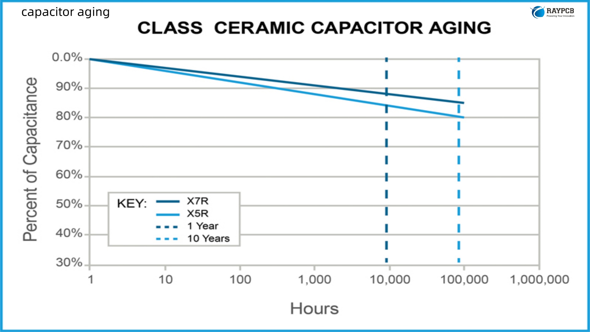
Q3: Do ceramic capacitors age the same way electrolytics do?

No โ€” ceramics age differently. Class II ceramics (X5R, X7R) exhibit capacitance loss due to dielectric polarization decay, but this is partially reversible by heating above the Curie temperature. They don’t have liquid electrolytes, so they don’t dry out. For high-reliability filter applications, ceramics generally outlast electrolytics by a significant margin under most operating conditions.

Q4: Can I slow down capacitor aging by running at lower voltage?

Yes, meaningfully so โ€” especially for larger snap-in and screw-terminal types. For small radial types, the voltage derating effect is less pronounced. For all sizes, temperature reduction is the single most effective aging mitigation. Voltage derating is a secondary but useful strategy, particularly when combined with a conservative thermal design.

Q5: What’s the difference between capacitor lifespan and MTBF?

These are often confused. Lifespan (endurance) describes when a single capacitor will wear out under specific conditions โ€” it’s a wear-out mechanism. MTBF is a statistical failure rate based on random failures during the normal operating period. If you parallel multiple capacitors, the MTBF of the assembly improves, but the lifespan of each individual component stays the same. Wear-out failure of any one cap can still cause system failure.

Understanding capacitor aging isn’t just academic โ€” it directly determines the service life of your product in the field. The Arrhenius equation gives you the tools to predict and control that degradation. Good layout, thermal management, voltage derating, and proactive replacement schedules are the engineering levers available to you. Use them, and capacitor aging becomes a managed risk rather than a mystery failure.

Bypass Capacitor: What It Does and How to Use It on a PCB

Bypass capacitor guide for PCB engineers: covers SRF, value selection tables, placement rules, common mistakes, and IC-specific strategies for clean power rails.

Every experienced PCB engineer has been there. The board passes simulation, the schematic looks correct, and then on the bench the microcontroller locks up randomly, the ADC readings are noisier than expected, or the digital logic occasionally throws spurious pulses. Half the time, the culprit is a missing or badly placed bypass capacitor.

Understanding what a bypass capacitor actually doesโ€”not just the textbook definition but the physical reality of why loop inductance kills its effectiveness and why “sprinkle them around the board” is genuinely bad adviceโ€”is one of those fundamentals that searates PCB designs that work reliably in production from ones that are quietly unreliable.

This guide covers the theory, the practical value selection, the placement rules that actually matter, and the common mistakes that show up repeatedly in design reviews.

What Is a Bypass Capacitor?

A bypass capacitor is a capacitor connected between a power supply rail and ground, placed close to an active component, with the specific purpose of providing a low-impedance local energy reservoir that can instantaneously supply current during fast switching transientsโ€”and simultaneously route high-frequency noise from the power rail directly to ground before it reaches the device’s supply pins.

The name comes from the function: high-frequency noise is “bypassed” around the sensitive circuitry to ground. One end of the bypass capacitor connects to the VCC (or other supply) pin of the IC, and the other end connects to the ground reference.

A clean DC voltage at the supply input of a power converter or regulator is not the same thing as a clean voltage at the power pin of an IC switching at 100 MHz or faster. The traces, vias, and power plane copper between the supply and the IC all have resistance, capacitance, andโ€”most criticallyโ€”inductance. That parasitic inductance resists instantaneous current changes. When a digital gate switches and demands a sharp spike of current, the power supply cannot respond fast enough because the parasitic inductance of the PDN (Power Distribution Network) between the supply and the IC limits the rate of current delivery.

The bypass capacitor is local to the IC. Because it is physically close, the parasitic loop inductance between the capacitor and the IC’s supply pins is very small. When the gate switches and demands current, the bypass capacitor discharges and supplies that current almost instantaneously, long before the power supply can react. After the transient, the power supply slowly recharges the bypass capacitor, ready for the next switching event.

Bypass Capacitor vs Decoupling Capacitor: Clearing Up the Confusion

These two terms are frequently used interchangeably, and in casual conversation that is often fine. In a design review, however, precision matters.

TermPrimary FunctionFrequency RangeTypical Value
Bypass capacitorRoute HF noise to groundHigh frequency (MHz range)1 nF โ€“ 100 nF
Decoupling capacitorSupply local transient current to ICMid frequency (kHzโ€“MHz)100 nF โ€“ 10 ยตF
Bulk capacitorEnergy reservoir for PDNLow frequency (Hzโ€“kHz)10 ยตF โ€“ 1000 ยตF

In practice, the same physical component placed between VCC and GND near an IC is doing both jobs simultaneouslyโ€”routing noise to ground and supplying transient current. The terminology difference is really about emphasis and scale. A 100 nF ceramic capacitor near a microcontroller’s VDD pin is typically called a bypass capacitor because its primary role at high frequency is shunting noise to ground. A 10 ยตF tantalum or electrolytic nearby is more commonly called a decoupling capacitor because its bulk charge storage supplies transient current demand. Both concepts describe aspects of the same power integrity challenge.

How a Bypass Capacitor Works: The Electrical Reality

To understand why placement and value matter so much, you need to think about a bypass capacitor not as an ideal component but as a real one with three parasitic elements: capacitance (C), equivalent series resistance (ESR), and equivalent series inductance (ESL).

Self-Resonant Frequency (SRF)

Every real capacitor has a self-resonant frequency (SRF), determined by its capacitance and ESL:

SRF = 1 / (2ฯ€ ร— โˆš(L ร— C))

Below the SRF, the component behaves as a capacitorโ€”impedance decreases with frequency. Above the SRF, the ESL dominates and the component behaves as an inductorโ€”impedance increases with frequency. This means every bypass capacitor has a frequency range where it is actually useful, and outside that range it is either doing very little or actively making things worse.

A 100 nF MLCC in a 0402 package typically has a SRF around 50โ€“100 MHz. A 10 ยตF ceramic in an 0805 package might resonate at 5โ€“10 MHz. A 100 ยตF electrolytic might resonate below 1 MHz. This is why a single bypass capacitor can never cover the full frequency range of a modern high-speed designโ€”you need a network of values.

The PDN Impedance Target

The goal of bypass capacitor strategy is to keep the impedance of the power distribution network flat and below a target level across the frequency range where the IC draws current. That target impedance (Z_target) is typically calculated as:

Z_target = Allowable voltage droop / Maximum transient current

For a 3.3 V microcontroller with a 5% tolerance (165 mV droop budget) drawing 500 mA transients, the target is 165 mV / 500 mA = 0.33 ฮฉ. The bypass capacitor networkโ€”in combination with the power and ground planesโ€”must maintain impedance below this threshold across frequency.

Bypass Capacitor Value Selection

This is the area most often handled by rule-of-thumb rather than analysis. The rules-of-thumb are reasonable starting points, but understanding why they work helps you deviate correctly when a design demands it.

Standard Value Guidelines

ApplicationRecommended ValuePackageNotes
High-speed digital IC (per power pin)100 nF (0.1 ยตF)0402 or 0603Standard starting point for most logic
High-speed IC supplementary bypass10 nF0402Placed closest to pin; handles higher freq
MCU / FPGA bulk decoupling1 ยตF โ€“ 10 ยตF0603 or 0805One per power rail, handles mid-freq
Board-level bulk storage47 ยตF โ€“ 470 ยตFElectrolytic or tantalumSupply rail energy reservoir
Analog IC / op-amp bypass100 nF 10 ยตF
RF IC / oscillator bypass100 pF + 10 nF0402Use lowest-inductance package available
DDR memory VDD bypassPer JEDEC spec, multiple values0402/0201Follow IC vendor layout guidelines

The 100 nF (0.1 ยตF) MLCC has been the dominant bypass capacitor value for decades because it resonates in a frequency rangeโ€”roughly 10โ€“100 MHzโ€”that aligns with the switching speeds of most digital logic. It is not a magic number; it is a practical starting point that can be tuned through simulation or measurement.

Choosing the Right Capacitor Type

The capacitor type matters almost as much as the value for bypass applications. Here’s how the main types compare:

TypeESRESLMax FrequencyTemperature StabilityCost
MLCC (ceramic X5R/X7R)Very lowVery low100 MHz+Good (X7R: ยฑ15%)Low
MLCC (C0G/NP0)Extremely lowVery low100 MHz+Excellent (ยฑ30 ppm/ยฐC)Medium
TantalumLowโ€“mediumLow1โ€“10 MHzGoodMedium
Aluminum electrolyticMediumโ€“highMedium<1 MHzPoor at extremesLow
Film (PP or PET)Very lowLow1โ€“10 MHzGoodMedium

For high-frequency bypass, MLCC ceramic capacitorsโ€”particularly X7R dielectric in 0402 or smaller packagesโ€”are the clear choice. Their extremely low ESL makes them effective at the frequencies where high-speed ICs need help most. C0G (NP0) ceramic is preferred in precision analog and RF bypass positions where capacitance must remain stable with voltage and temperature.

One critical note on MLCC capacitors: X5R and X7R types exhibit significant capacitance reduction under DC bias. A 100 nF X5R capacitor rated at 10 V may only deliver 60โ€“70 nF at its actual operating voltage of 3.3 V. Always derate accordingly, or use the manufacturer’s derating curves to verify actual capacitance at the operating point.

How to Place a Bypass Capacitor: PCB Layout Rules That Actually Matter

Selecting the right value is only half the job. A correctly specified bypass capacitor placed badlyโ€”or routed sloppilyโ€”can perform worse than a poorly specified capacitor placed well. Placement is where most design errors with bypass capacitors actually occur.

Rule 1: Minimize Loop Inductance Above All Else

The parasitic inductance of the bypass capacitor loopโ€”from the IC’s power pin, through the trace to the capacitor, through the capacitor, back through the ground trace to the IC’s ground pin, and back to the power pinโ€”determines how effective the capacitor is at high frequency. Every nanometer of trace length adds inductance. Every via adds inductance. At 100 MHz, even 1 nH of extra loop inductance is meaningful.

To minimize loop inductance, keep bypass capacitors as close to the IC power and ground pins as physically possible. On a two-layer board, this means right beside the power pin with the shortest possible traces. On a four-layer board with inner power and ground planes, place the capacitor’s via immediately adjacent to the capacitor pads, not at the end of a long stub trace.

Rule 2: Place on the Opposite Side When Possible

Placing the bypass capacitor on the bottom side of the board, directly underneath the IC’s power pin position, is often the best option. This keeps the connection loop very short, avoids consuming routing space on the top side, and frequently allows via-in-pad construction that further reduces loop inductance. The ground return path through a device ground pin to the capacitor beneath it is shorter and less inductive than routing along the top side of the board.

Rule 3: Order Multiple Capacitors by Value

When multiple bypass capacitors of different values serve the same IC power pin, place the smallest-value capacitor physically closest to the pin. The smallest capacitor has the highest SRF and handles the fastest (highest-frequency) transients. The larger capacitors handle lower-frequency transients and can tolerate slightly more physical distance from the pin.

For example, a typical arrangement might look like:

  • 10 nF (0402) โ€” placed directly adjacent to the IC power pin, or underneath it
  • 100 nF (0402) โ€” placed next, just beyond the 10 nF cap
  • 10 ยตF (0805) โ€” placed nearby, slightly further away but still local to the IC

Rule 4: Keep Vias Short and Multiple

The via from the bypass capacitor pad to the power plane (or ground plane) adds series inductance. Use multiple vias in parallel when possibleโ€”each via in parallel halves the via inductance. On dense boards, via-in-pad construction (vias drilled directly through the capacitor land pads) is the gold standard for minimizing loop inductance, though it requires filling and plating the vias to provide a flat solder surface.

Rule 5: Avoid Daisy-Chaining Through the Bypass Capacitor

A routing practice that occasionally appears on older boards is “sequencing” the bypass connection: power plane โ†’ bypass capacitor โ†’ IC pin. The intent is to force all supply current through the capacitor as a filter. This is incorrect for high-speed designs. The trace from the capacitor to the IC pin adds series inductance that partially counteracts the capacitor’s effectiveness. The correct routing connects the bypass capacitor directly to the IC’s power and ground pins with the shortest possible loop, and separately connects to the power and ground planes.

Rule 6: One Bypass Capacitor Per Power Pin

ICs with multiple power supply pinsโ€”common in FPGAs, high-performance microcontrollers, and DDR memory interfacesโ€”need at least one bypass capacitor per power pin, not one capacitor shared across multiple pins. Each power pin has its own transient current demand, and a capacitor at one pin cannot effectively supply transient current to a pin several millimeters away at switching speeds.

Bypass Capacitor Placement: Common Mistakes to Avoid

MistakeWhy It MattersCorrect Practice
Placing bypass caps far from ICIncreased loop inductance nullifies HF effectivenessPlace within 1โ€“2 mm of IC power pin
Using one large cap instead of parallel valuesOne value can’t cover full frequency rangeUse 10 nF + 100 nF + 1โ€“10 ยตF in parallel
Long trace between cap and IC pin~7 nH/inch on FR-4; kills HF performanceUse shortest trace possible or via-in-pad
Skipping bypass on “quiet” analog ICsOp-amps still need supply bypassing100 nF ceramic + 10 ยตF bulk per supply pin
Using electrolytic only for HF bypassHigh ESR and ESL; poor above ~1 MHzCeramic MLCC for HF, electrolytic for bulk
Sharing one bypass cap across multiple power pinsEach pin has independent transient demandOne bypass cap per supply pin
Not derating MLCC capacitance for DC biasX7R/X5R capacitance drops significantly under DCVerify actual capacitance at operating voltage

Bypass Capacitor Strategy for Specific IC Types

Microcontrollers and DSPs

For most modern 32-bit MCUs (ARM Cortex-M series, for example), the datasheet will specify the recommended bypass capacitor arrangement explicitly. A typical recommendation is 100 nF ceramic at each VDD pin plus a shared 4.7โ€“10 ยตF bulk ceramic or tantalum capacitor. Follow the IC vendor’s layout guidelines preciselyโ€”they test these recommendations against their specific die and package inductances.

FPGAs

FPGAs are the most demanding bypass capacitor consumers on a board. A mid-range FPGA may have dozens of VCC and VCCIO pins, each needing individual bypass. The FPGA vendor’s power guidelines (Xilinx/AMD, Intel/Altera, Lattice all publish detailed PDN application notes) will specify required capacitor values, quantities, and placement rules. Skipping this step and just “sprinkling” 100 nF caps is a reliable way to cause random fabric errors under load.

Analog ICs and Op-Amps

For analog ICs, bypass capacitor selection focuses on keeping supply noise out of the signal path. A 100 nF X7R ceramic handles high-frequency noise. A 10 ยตF tantalum or ceramic handles mid-frequency supply variations. For very low-noise analog front-ends, C0G ceramics are preferred because their capacitance is voltage- and temperature-independent, preventing the capacitor itself from modulating the supply impedance.

RF and High-Speed Serial ICs

RF ICs and SerDes transceivers (PCIe, USB 3.x, Ethernet PHYs) often require very small bypass capacitorsโ€”as small as 100 pFโ€”in addition to standard 100 nF caps. These tiny capacitors handle frequencies above the SRF of the 100 nF cap. The vendor’s layout guidelines are mandatory reading; RF IC bypass layouts are often extremely specific about capacitor placement relative to the IC body.

Bypass Capacitor Value Calculator Reference

Use this quick reference table for common IC supply rails:

Supply VoltageIC TypeRecommended Bypass Network
3.3 VGeneral digital logic100 nF (0402) per power pin + 10 ยตF bulk
3.3 VHigh-speed MCU/DSP10 nF (0402) + 100 nF (0402) + 10 ยตF
1.8 V / 1.2 VFPGA corePer vendor PDN guide; typically 100 nF ร— 4โ€“6 + 10โ€“47 ยตF
5 VTTL / legacy logic100 nF (0603) per IC + 47โ€“100 ยตF bulk per supply section
ยฑ15 VPrecision op-amp100 nF ceramic + 10 ยตF electrolytic per supply rail
3.3 VRF IC100 pF (0402) + 10 nF (0402) + 100 nF (0402)
1.0โ€“1.2 VDDR memory VDDPer JEDEC/vendor: 100 nF per device + bulk 100โ€“470 ยตF

Useful Resources for Bypass Capacitor Design

These are the reference materials that belong in any serious PCB engineer’s bookmarks:

TI Application Report SLOA089 โ€“ Bypass Capacitor, Its Functions, Selection and Application โ€” ti.com โ€” Clear, practical Texas Instruments guide covering selection, placement, and value calculation.

Altium Designer PDN Analyzer Documentation โ€” altium.com โ€” In-tool PDN impedance analysis that can validate bypass capacitor networks before fabrication.

Murata SimSurfing Impedance Simulator โ€” ds.murata.com/simsurfing โ€” Simulate impedance vs frequency for Murata MLCC types; essential for verifying SRF and capacitance under DC bias.

Wรผrth Elektronik REDEXPERT โ€” we-online.com/redexpert โ€” Excellent tool for simulating real-world capacitor behavior including DC bias derating for Wรผrth MLCC products.

Henry Ott Consultants โ€“ Decoupling and Bypassing โ€” hottconsultants.com โ€” Henry Ott’s seminal work on EMC and signal integrity is required reading; his articles on bypass and decoupling remain foundational.

Digi-Key MLCC Parametric Search โ€” digikey.com/capacitors โ€” Real-time stock, pricing, and datasheet access with derating curve data for major MLCC manufacturers.

IPC-2141A โ€“ Controlled Impedance Circuit Boards and High-Speed Logic Design โ€” ipc.org โ€” Industry standard covering PCB design guidelines including power distribution and decoupling requirements.

Frequently Asked Questions About Bypass Capacitors

What value bypass capacitor should I use?

The standard starting point is 100 nF (0.1 ยตF) ceramic MLCC at each IC power supply pin. For high-speed designs, pair this with a 10 nF ceramic for higher-frequency bypassing placed closer to the pin, and a 1โ€“10 ยตF bulk capacitor for lower-frequency decoupling placed nearby. Always check the IC vendor’s datasheet and layout guidelinesโ€”many modern ICs specify their required bypass network explicitly, and deviating from it can cause reliability issues that are difficult to debug.

How close to the IC does a bypass capacitor need to be?

As close as physically practicalโ€”ideally within 1โ€“2 mm of the IC’s power pin. The critical metric is the loop inductance of the bypass path, which increases with trace length at roughly 7โ€“10 nH per inch on a standard FR-4 board. Even a short 5 mm trace adds 1.5โ€“2 nH of series inductance, which can meaningfully degrade the capacitor’s effectiveness above 50โ€“100 MHz. On multi-layer boards with power planes, placing the bypass capacitor on the opposite side of the board directly beneath the IC’s power pin is often the most effective approach.

Can I use one large capacitor instead of multiple small bypass capacitors?

Not effectively for high-frequency bypassing. A single 10 ยตF capacitor has a lower self-resonant frequency than a 100 nF capacitor, so it becomes inductiveโ€”and therefore ineffective as a bypassโ€”at the high frequencies where digital ICs need help most. Parallel combinations of capacitors with different values cover a broader frequency range. The 10 nF + 100 nF + 10 ยตF combination provides overlapping coverage from roughly 1 MHz to several hundred MHz, which a single large value cap simply cannot match.

Why does my circuit still have noise even with bypass capacitors installed?

The most common reason is placementโ€”the bypass capacitors are the right value but are positioned too far from the IC’s power pins, allowing too much parasitic inductance in the bypass loop. Other causes include incorrect routing (traces that are too long or too narrow between the cap and the IC pin), insufficient via connections to the ground plane, absence of a solid ground plane, or the capacitance value being mismatched to the frequency of the noise problem. Measure the noise frequency with a scope and verify that the bypass capacitor’s self-resonant frequency actually falls in that range. If the dominant noise is at 200 MHz, a 100 nF cap with an SRF of 50 MHz won’t helpโ€”you need smaller-value, lower-inductance caps.

Is a bypass capacitor the same as a decoupling capacitor?

Functionally, they are related but not identical, though the terms are often used interchangeably in schematics and BOMs. A bypass capacitor specifically routes high-frequency noise from the power pin to ground. A decoupling capacitor acts as a local charge reservoir that supplies transient current to the IC, keeping supply voltage stable during fast switching events. In practice, a single capacitor placed between VCC and GND near an IC performs both functions simultaneously. The distinction becomes meaningful mainly when designing a layered bypass strategyโ€”small ceramics for high-frequency bypass, larger ceramics or tantalums for mid-frequency decoupling, and bulk electrolytics for low-frequency energy storage.

Summary

The bypass capacitor is one of those components that gets taken for granted until the design is on the bench and something is clearly wrong. Getting bypass capacitor strategy right means thinking through three things together: the right value (or set of values) for the frequency range that matters, the right capacitor type with appropriately low ESR and ESL, andโ€”most criticallyโ€”the right placement with minimal loop inductance.

A 100 nF MLCC placed 10 mm from the IC with a long trace connecting it is far less effective than the same 100 nF cap placed 1 mm away with a direct via to the ground plane. The physics are the same whether you are designing a simple single-supply MCU board or a multi-rail FPGA platform. Loop inductance is the enemy, proximity is the solution, and layered bypass networks are what make the strategy complete across frequency. Understanding your capacitor choices at this level of depth is what separates designs that pass first-article testing from designs that need another revision spin.

Audio Capacitor Guide: Coupling, Bypass & Crossover Selection

Choosing the right audio capacitor for coupling, bypass, or crossover? Compare polypropylene, polyester, electrolytic, and ceramic with practical selection tables.

Ask ten audio engineers which capacitor sounds best and you’ll get ten different answersโ€”some informed by measurement, some by legend, and a few by genuine listening experience on revealing systems. The truth, as usual, sits in the engineering data rather than the mythology. Understanding what an audio capacitor actually does in each circuit position, and why certain dielectric types perform better than others in those positions, cuts through most of the noise.

This guide covers the three main audio capacitor applicationsโ€”coupling, power supply bypass, and speaker crossoverโ€”with practical selection guidance grounded in what the datasheets, impedance measurements, and physics actually tell us.

Why Audio Capacitors Are a Separate Conversation

Most of the time, choosing a capacitor is a straightforward exercise in matching value, voltage rating, and package to a circuit position. Audio design adds a layer of complexity because capacitors in the signal path are working with dynamic, frequency-sensitive electrical signals that a loudspeaker or headphone driver converts directly into mechanical motion that a human ear evaluates. Several capacitor characteristics that are irrelevant in a digital power rail position become audibleโ€”or at least measurableโ€”in an audio signal path.

The three parameters that drive audio capacitor selection, beyond the basic value and voltage specification, are equivalent series resistance (ESR), dissipation factor (DF), and dielectric absorption (DA). Understanding each is the starting point for making defensible component choices.

ESR in Audio Circuits

ESR represents the total resistive loss inside a real capacitor. In a crossover network, a capacitor’s ESR adds series resistance that slightly shifts the crossover frequency and introduces frequency-dependent losses. Measurements using an impedance analyzer show that electrolytics have high series resistance compared to polypropyleneโ€”an amount that is not negligible in crossover design, comparable to the series resistance that designers routinely model in inductors. Polypropylene film capacitors have ESR values low enough that they are typically below the noise floor of most measurement instruments in audio frequency bands.

Dissipation Factor

Dissipation factor (DF) is the ratio of energy lost per cycle to energy stored. Notice how capacitance drops with frequency and dissipation factor rises in electrolytic capacitorsโ€”electrolytics show around a 10% change in capacitance from 100 Hz to 10 kHz, while polypropylene capacitors are fairly linear in capacitance with frequency and most have dissipation factors too low to reliably measure. In a coupling capacitor carrying a small signal voltage, the practical consequences of DF are debated. In a crossover capacitor handling watts of power, a high DF means the capacitor heats up internallyโ€”shortening its life and shifting its capacitance value as temperature rises.

Dielectric Absorption

Dielectric absorption is the tendency of a capacitor’s dielectric to retain a residual charge after it has been discharged, releasing it slowly afterward. Low dielectric absorption keeps transient responsesโ€”like the attack of a snare drum or the pluck of a guitar stringโ€”reproduced clearly. Polypropylene’s DA is typically below 0.02%. Polyester runs around 0.2%. Standard electrolytics can be 2โ€“5%. In a sample-and-hold circuit this difference is decisive. In an audio coupling capacitor with a small AC signal riding on DC bias, the effect is small and contested; in a crossover carrying significant signal power the effect is larger and more defensible.

Audio Capacitor Types: What’s Actually Available

Before getting into application-specific guidance, here is a practical comparison of the main capacitor types used in audio work and their key characteristics.

TypeESRDissipation FactorDielectric AbsorptionPolarityAudio Signal Path?
Polypropylene film & foilVery low<0.02%<0.02%Non-polarExcellent
Metallized polypropylene (MKP)Low<0.1%<0.05%Non-polarVery good
Polyester / PET (MKT)Low-medium1.0โ€“1.5%~0.2%Non-polarAcceptable
Non-polar electrolytic (NP)Mediumโ€“high2โ€“15%1โ€“5%Non-polarBudget only
Polar electrolyticHigh2โ€“50%2โ€“5%PolarizedPower supply only
C0G / NP0 ceramicVery low<0.1%NegligibleNon-polarBypass/decoupling only
X7R ceramicLow~1.0%ModerateNon-polarDecoupling only
PolystyreneExtremely low<0.02%<0.02%Non-polarExcellent (legacy)

High-k ceramic capacitors such as X7R and Z5U are perfectly suited for bypassing and decoupling op-amp supply rails, but should never be used for audio coupling, in filters, tone controls, or anywhere else in the signal pathโ€”these caps are designed for supply rail decoupling, not to replace film caps. They exhibit a piezoelectric effect where they vibrate under AC current and generate a small voltage when mechanically disturbed, which shows up as audible distortion called microphonics.

Coupling Capacitors in Audio Amplifiers

A coupling capacitor sits in series with the audio signal path, passing AC audio frequencies while blocking any DC offset between circuit stages. The DC bias of a transistor, FET, or op-amp output stage must not reach the next stage’s inputโ€”it would shift the operating point, cause distortion, or in the case of a speaker output, drive the driver to one extreme of its travel.

How to Calculate Coupling Capacitor Value

The coupling capacitor forms a high-pass filter with the input impedance of the following stage. The โ€“3 dB cutoff frequency is:

f = 1 / (2ฯ€ ร— R ร— C)

For a 20 Hz lower frequency limit (the bottom of human hearing) with a 10 kฮฉ input impedance following stage:

C = 1 / (2ฯ€ ร— 10,000 ร— 20) = approximately 800 nF โ†’ use 1 ยตF

For a 2 kฮฉ input impedance, you’d need 4 ยตF to maintain the same lower cutoff. In practice, coupling capacitor values in amplifier stages run from around 470 nF to 10 ยตF depending on source and load impedances.

What Capacitor to Use for Audio Coupling

For small-signal coupling in a line-level or preamplifier stageโ€”where the signal voltage across the capacitor is smallโ€”a well-chosen polyester (MKT) film capacitor is entirely adequate for most designs. Polypropylene is better on measured parameters and preferred in high-performance designs, but the signal voltage across a coupling capacitor in normal operation is so small that the difference in distortion is largely theoretical at typical listening levels.

For large-signal couplingโ€”output coupling in a power amplifier stage, or tube amplifier coupling where the capacitor sees significant signal voltageโ€”the choice matters more. Polypropylene film-and-foil is the correct dielectric. When it comes to high current applications such as passive loudspeaker crossover networks, there will be significant voltage across the capacitor and current through it, and the devices used need to be stable with time and temperatureโ€”this generally means polypropylene, polyester, or paper-in-oil.

One practical issue with large coupling capacitors in tube amplifiers is that polypropylene film-and-foil types become physically large and expensive above about 2โ€“4 ยตF. A common engineering compromise is to use a smaller-value polypropylene capacitor for the high-frequency signal path and bypass it with a larger-value bipolar electrolytic for the low-frequency extensionโ€”keeping the polypropylene cap in the dominant signal path where it matters most.

Coupling Capacitor Selection Table

StageSignal LevelRecommended DielectricTypical Value Range
Phono preamp inputVery small (mV)Polypropylene (PP)100 pF โ€“ 10 nF
Line-level preamplifierSmall (100 mV โ€“ 1 V)PP or polyester (MKT)470 nF โ€“ 2.2 ยตF
Tube amplifier interstageMedium (1โ€“10 V)PP film & foil1 ยตF โ€“ 10 ยตF
Solid-state power amp outputLarge (1โ€“30 V)Non-polar electrolytic or PP1000 ยตF โ€“ 10,000 ยตF
Headphone amp outputSmallโ€“mediumPP film100 ยตF โ€“ 470 ยตF (or DC-coupled)
Tone control networkSmallPolyester (MKT) acceptable10 nF โ€“ 100 nF

Bypass Capacitors in Audio Power Supplies

The bypass capacitor in an audio context refers primarily to the capacitors used to decouple the power supply rails of op-amps and audio IC stages. This is where the ceramic capacitor discussion entersโ€”and where understanding the distinction between signal-path and supply-path decisions matters enormously.

Op-Amp Supply Bypass in Audio Circuits

Every op-amp used in an audio circuit needs bypass capacitors on its supply pins. The op-amp draws transient currents as it responds to audio signals, and without a local energy reservoir, the supply voltage droops, injecting supply noise into the output. The standard approach is to place a 100 nF X7R ceramic MLCC directly at each supply pin, possibly supplemented by a 10 ยตF tantalum or electrolytic further away for bulk energy storage.

X7R multilayer ceramic capacitors are perfectly alright for bypassing and decoupling op-amp supply rails, and that is what they were designed forโ€”don’t believe anyone who claims otherwise. The ceramic capacitor’s low ESR and low ESL make it effective at the high frequencies where op-amp supply rejection degrades. The fact that X7R has relatively poor capacitance stability with DC bias is irrelevant here because it is working against an AC supply impedance, not as a precision signal component.

Audio-Specific Power Supply Bypass Strategy

Supply PositionRecommended Bypass CapacitorNotes
Op-amp VCC/VEE pin (HF)100 nF X7R ceramic (0402/0603)Place within 1โ€“2 mm of supply pin
Op-amp VCC/VEE pin (LF)10 ยตF electrolytic or tantalumBulk charge reservoir
Audio IC power rail100 nF ceramic + 100 ยตF electrolyticStandard dual-value approach
Voltage regulator output100 nF ceramic + 10โ€“22 ยตF electrolyticCheck regulator’s minimum ESR requirement
Reference bypass (precision DAC)1โ€“10 ยตF C0G or filmNoise-sensitive; avoid X5R/X7R here
Phantom power rail (microphone preamp)10 ยตF + 100 nFLow-noise supply essential

For the reference voltage bypass on a high-precision DAC or ADC, C0G ceramic or a small film capacitor is preferred over X7R, because C0G has no capacitance variation with voltage or temperatureโ€”keeping the reference impedance precisely defined across operating conditions.

Crossover Capacitors: The Most Demanding Audio Application

The passive loudspeaker crossover network is where capacitor selection has the clearest, most measurable impact on audio performanceโ€”and where getting it wrong has the most direct consequences. Unlike a small-signal coupling capacitor that sees millivolts, a crossover capacitor in a 100-watt speaker system may carry several amps of AC current at audio signal voltages up to tens of volts. The dielectric is working hard.

How a Crossover Capacitor Works

In a first-order crossover high-pass filter feeding a tweeter, the crossover capacitor is in series with the tweeter. Below the crossover frequency the capacitor’s impedance is high, attenuating low frequencies. Above the crossover frequency the capacitor passes freely. The crossover frequency is:

f_crossover = 1 / (2ฯ€ ร— C ร— Z_speaker)

For an 8 ฮฉ tweeter with a 10 ยตF capacitor:

f = 1 / (2ฯ€ ร— 0.000010 ร— 8) โ‰ˆ 2,000 Hz

Any resistance in the capacitor (ESR) adds to this 8 ฮฉ load, shifting the crossover frequency upward and introducing power dissipation. Any non-linearity in the capacitor’s behavior causes harmonic distortion in the audio signal passing through to the tweeter.

Why Ceramics Fail in Crossover Positions

Ceramic capacitors are susceptible to microphonic effectsโ€”converting mechanical vibrations into electrical signals that can significantly distort audio signals. Moreover, the low insulation resistance and relatively high ESR of ceramic capacitors make them unsuitable for crossover networks. Inside a speaker cabinet that is vibrating at acoustic frequencies, a ceramic MLCC will generate noise voltages. This is not a subtle effectโ€”it is directly measurable and in a tweeter position, directly audible.

Why Standard Electrolytics Are Problematic

The performance of a standard non-polar aluminum electrolytic capacitor creates distortion when it is used in audio AC applications. Off-the-shelf single non-polar design capacitors have an extremely high dissipation factor ranging from 2% to 150%, which results in excessive heating and shortened life in audio applications.

Beyond DF, electrolytics exhibit capacitance that drifts with frequency, temperature, and age. After 10โ€“15 years, electrolytic capacitors in crossovers often no longer hold their rated valueโ€”and they can explode with overvoltages from powerful amplifiers. For a high-end loudspeaker expected to perform accurately for decades, an electrolytic crossover cap is a design compromise that accumulates interest over time.

The Case for Polypropylene in Crossovers

Polypropylene capacitors stand out as the preferred choice for high-end audio crossover applications. Their low dielectric absorption keeps transient responses reproduced clearly. Polypropylene film is stable during temperature fluctuations, so speakers will sound consistent whether in a cold basement or a warm dedicated listening room. Ultra-low ESR and minimal inductance allow them to pass high frequencies with minimal phase shift or energy loss.

Film capacitor selection is extremely important for acceptable quality sound reproduction. The ESR and dielectric absorption of film capacitors must be as low as possible to avoid distortion, and film-and-foil polypropylene constructions are designed specifically for audio applications, providing low ESR, low DA, high insulation resistance, and wide temperature range.

Film-and-foil types (where both electrodes are separate sheets of metal foil, not vacuum-deposited metallization) offer the lowest ESR of any film capacitor construction. Their price is significantly higher, but in tweeter positions of serious loudspeaker designs, they are the accepted standard.

Crossover Capacitor Selection by Speaker Position

Speaker PositionSignal LevelRecommended TypeNotes
Tweeter (high pass)HighPP film & foil, or metallized PPMost revealing position; use highest quality
Midrange (bandpass)Mediumโ€“highMetallized PP (MKP)Good performance at moderate cost
Woofer (low pass, shunt)HighNP electrolytic + PP bypassLarge values; mixed approach works
Budget full-rangeAnyNon-polar electrolytic (NP)Accept performance trade-off
High-end 3-way systemAll positionsPP film & foil throughoutConsistent performance across system

Crossover Capacitor Value Formula

C (ยตF) = 159,000 / (f_crossover_Hz ร— Z_speaker_ฮฉ)

For a 3,000 Hz crossover into an 8 ฮฉ tweeter: C = 159,000 / (3,000 ร— 8) = 6.625 ยตF โ†’ use 6.8 ยตF standard value

For a 2,500 Hz crossover into a 6 ฮฉ tweeter: C = 159,000 / (2,500 ร— 6) = 10.6 ยตF โ†’ use 10 ยตF standard value, or parallel values to reach exact target

Voltage Rating for Crossover Capacitors

For most passive crossover applications it does not matter whether the capacitor is rated at 100, 200, 250, 400, 630, 800 or 1200 V DCโ€”what matters is the RMS AC rating of the speaker system. A 100-watt amplifier into an 8 ฮฉ load produces up to 28 V RMS. Select a crossover capacitor rated for at least twice the maximum expected RMS voltageโ€”so 63 V AC or 100 V DC minimum for most home systems. Never use a part just at its limit; derating is good engineering practice in audio as much as in industrial electronics.

Choosing the Right Audio Capacitor: Full Decision Framework

Understanding how a capacitor fits into an audio circuit is not just about selecting a dielectricโ€”it requires matching the component’s full specification to the electrical stresses and performance requirements of the specific circuit position. Use this framework when making audio capacitor selections:

Circuit PositionPriority ParameterSecondary ParameterAvoid
Small-signal coupling (preamp, DAC)Low ESR, low DAValue stability over temperatureX7R/X5R ceramic
Large-signal coupling (power amp)Low DF, voltage ratingPhysical sizeStandard polar electrolytic
Supply bypass (op-amp, IC)Low ESR at HFValue under DC biasFilm caps (overkill, wrong tool)
Precision reference bypassValue stability vs. voltageLow ESRX5R/X7R ceramic
Tweeter crossoverLow DF, low DA, low ESRAC voltage ratingAny electrolytic, all ceramics
Midrange crossoverLow DF, low ESRCost per ยตFStandard polar electrolytic
Woofer crossover (budget)AC voltage rating, value accuracyDF acceptableClass Y or X capacitors (safety types)
Tube amplifier signal pathLow DA, low DFPhysical size and costStandard electrolytic, X7R ceramic

Useful Resources for Audio Capacitor Selection

These reference sources are worth bookmarking for any serious audio PCB or loudspeaker project:

Elliott Sound Products โ€“ Capacitor Characteristics โ€“ sound-au.com/articles/capacitors.htm โ€” One of the most technically rigorous and honestly written articles on capacitor behavior in audio circuits. Essential reading before specifying any signal-path capacitor.

Jantzen Audio โ€“ Capacitor Types and Where to Use Them โ€“ jantzen-audio.com/faq โ€” Practical guidance from one of the premier European audio capacitor manufacturers, with hierarchy from entry-level to reference grade.

Electrocube Technical Bulletin โ€“ Capacitors in Crossover Networks โ€“ electrocube.com โ€” Detailed technical bulletin with measured data on electrolytic vs. film performance in speaker crossover applications.

Passive Components Industry Forum โ€“ Capacitor Selection for Coupling and Decoupling โ€“ passive-components.eu โ€” Technical industry-level overview of dielectric properties and selection criteria.

Digi-Key Film Capacitor Parametric Search โ€“ digikey.com/film-capacitors โ€” Real-time stock, pricing, and datasheet access across all major PP, MKP, and MKT film families.

Parts Express Crossover Design Resources โ€“ parts-express.com โ€” Practical supplier with crossover capacitor stock from major audio brands including Dayton, Jantzen, and Mundorf.

Vishay Film Capacitor Selection Guide โ€“ vishay.com โ€” Comprehensive technical datasheet covering dissipation factor, temperature coefficients, and voltage derating curves for metallized film types.

Frequently Asked Questions About Audio Capacitors

Can I use a ceramic capacitor in an audio signal path?

For supply bypassing and decoupling of op-amp power rails, yesโ€”X7R ceramics are the right tool for that job and work well. For the audio signal path itselfโ€”coupling, crossover, tone controlโ€”ceramics are problematic. X7R and X5R types introduce measurable distortion from their voltage coefficient of capacitance, and most ceramics exhibit microphonics: they convert vibration into electrical noise, which is particularly bad inside a loudspeaker enclosure. Use film capacitors in any position where the audio signal passes through the capacitor.

How important is the capacitor brand in audio crossover design?

The dielectric type matters more than the brand for the fundamental performance parameters. A generic metallized polypropylene capacitor from a reputable manufacturer will outperform a premium brand non-polar electrolytic in every measured parameter relevant to audio. Within polypropylene types, film-and-foil construction generally outperforms metallized construction due to lower contact resistance at the lead terminations. Exotic and premium-priced audio capacitors from brands like Mundorf, Clarity Cap, and Jantzen do exist in a market driven partly by audiophile preferenceโ€”but the biggest gains come from choosing the right dielectric family first, before worrying about which brand’s polypropylene to use.

Why do electrolytic capacitors age and what effect does it have on crossover performance?

Electrolytic capacitors age primarily because their liquid electrolyte slowly evaporates, especially at elevated temperatures. As electrolyte depletes, capacitance decreases and ESR rises. In a speaker crossover, falling capacitance shifts the crossover frequency upwardโ€”progressively reducing bass output and altering the transition band between drivers. In a tweeter high-pass filter, a significant capacitance drop could expose the tweeter to more low-frequency energy than it was designed to handle, potentially causing damage. Film capacitors age far more slowlyโ€”a well-made polypropylene crossover cap should maintain its value within tolerance for 20โ€“30 years under normal conditions.

What is the right voltage rating for an audio coupling capacitor?

The voltage rating must cover the maximum DC bias voltage plus the peak AC signal voltage that will appear across the capacitor in normal operation. For a preamp coupling cap that blocks a 15 V DC rail, the capacitor sees up to 15 V DC plus any signal swing. A 50 V or 63 V rated capacitor provides comfortable margin. For tube amplifier coupling capacitors, plate voltages can be 200โ€“400 V, requiring capacitors rated at 400โ€“630 V DC. Always check the worst-case bias conditions in the circuit, not just the nominal operating point. Under-rating a coupling capacitor results in dielectric breakdown over time, causing the capacitor’s insulation resistance to fall and eventually creating a DC leakage path that degrades the circuit’s operating point.

Is it worth upgrading crossover capacitors in existing speakers?

It depends on the starting quality. If the speakers came from the factory with standard non-polar electrolytic crossover capacitors, upgrading the tweeter crossover cap to a metallized polypropylene type of the same value will almost certainly produce a measurable improvement in the crossover network’s impedance flatness and could be audibly beneficial, particularly if the electrolytics have aged significantly. The tweeter position is where the improvement is most likely to be noticeable, since the tweeter handles the most revealing high-frequency information. Upgrading woofer crossover caps is a lower-priority investmentโ€”the performance difference at bass frequencies is smaller and harder to detect. Match the capacitance value precisely when upgrading; even a 5% shift in a tweeter crossover cap changes the crossover frequency noticeably.

Summary

The audio capacitor conversation is more disciplined than the audiophile community sometimes makes it appear. Ceramics belong in supply bypass positions, not in signal paths. Electrolytics belong in bulk power storage and budget large-value positions, with their limitations clearly understood. Polypropylene filmโ€”and particularly film-and-foil constructionโ€”is the correct dielectric for demanding signal-path positions: tweeter crossovers, tube amplifier coupling caps, and any application where the capacitor carries significant AC signal current. Polyester (MKT) is an entirely acceptable compromise for lower-stress signal positions in cost-constrained designs.

The engineering decision framework is straightforward: identify the electrical stresses the capacitor will see (signal voltage, current, DC bias, frequency range), match those to the dielectric type that handles them without measurable degradation, and select a value that achieves the required cutoff frequency with appropriate margin on voltage rating. When in doubt, polypropylene is almost always the right answer in the signal pathโ€”and C0G ceramic is almost always the right answer on the supply rail.

10000uF Capacitor: When & Why to Use Super-Large Electrolytics

Learn when and why to use a 10000uF capacitor โ€” covers high-power audio amplifier supplies, motor drives, inrush current protection, ESR selection, voltage derating, and PCB layout tips. Practical guide written from a PCB engineer’s perspective.

Most power supply designs never need more than a few hundred microfarads. Then you hit a class A amplifier, a high-current motor drive, or an industrial UPS, and suddenly you’re specifying a 10000uF capacitor โ€” a component that looks more like a chemistry flask than a passive component and weighs more than everything else on the board combined. At this scale, the engineering trade-offs shift dramatically. Inrush current becomes a real problem. Ripple current ratings and ESR matter more than the capacitance number on the label. Physical size and weight become mechanical design considerations. And lifespan calculations can’t be ignored.

This guide explains when a 10000uF capacitor is the right answer, how to select one correctly, the traps that catch out even experienced engineers, and where this size capacitor actually earns its place in a circuit.

What Is a 10000uF Capacitor and What Does It Store?

At 10,000 microfarads, you’re holding a meaningful amount of joules. Using E = ยฝCVยฒ, a 10000uF cap charged to 50V stores 12.5 joules of energy. For comparison, a 1000uF cap at the same voltage holds 1.25J โ€” ten times less. That energy difference is tangible: a 10000uF reservoir can sustain a 10A load for 25 milliseconds before drooping by 5V. In audio terms, that’s enough reserve energy to reproduce a sharp bass transient without rail sag. In motor drive terms, it’s the energy that keeps the DC bus stable during a fast load step.

The typical capacitance range of electrolytic capacitors spans from 1ยตF to 100,000ยตF, with their broad availability in different form factors allowing designers to select the best-fitting component with respect to width and height. At 10,000ยตF, you are firmly in the territory where aluminum electrolytic is virtually the only practical technology โ€” polymer tantalum tops out far below this value, and ceramic capacitors achieving this capacitance would require impractical PCB real estate.

When Does a Circuit Actually Need 10000uF?

This is the first question any engineer should ask. Reaching for a 10000uF capacitor without quantifying the need is lazy engineering โ€” you’ll pay in board space, inrush current headaches, and BOM cost. But there are applications where this value is the right call and nothing smaller will do.

High-Power Audio Amplifier Power Supplies

This is the most common application for 10000uF capacitors in consumer and professional electronics. The traditional design rule of thumb โ€” 2,000uF per amp of load current โ€” means a 5A amplifier supply needs 10,000uF per rail as a minimum. For a 100W/8ฮฉ amplifier, peak rail current approaches 5A, which lands directly on the 10,000uF threshold.

It’s not unusual to see 60,000uF per channel in class A amplifiers โ€” so a pair of 10000uF caps per rail is actually a conservative starting point in high-end audio work. Audio engineers choosing between a few large caps or many smaller ones in parallel should know that high performance amplifier supplies may use multiple smaller capacitors in parallel to achieve high capacitance while overcoming inductance and ESR limitations.

DC Motor Drive and Servo Systems

Brushed and brushless DC motors draw current in pulsed, highly dynamic patterns. When a motor accelerates under load, it demands a burst of current that the DC-DC converter or rectifier can’t supply fast enough on its own. A bulk 10000uF capacitor across the motor supply rail absorbs this demand, keeping the bus voltage stable and protecting the converter from destructive voltage spikes caused by motor back-EMF.

For a PWM motor drive, bulk capacitance is needed to sustain voltage during current transitions such as motor start-up, changes in load torque, or PWM operation. The formula for required bulk capacitance is: C_BULK = ฮ”I_MOTOR ร— T_PWM / ฮ”V_SUPPLY. At 20kHz PWM with a 5A current variation and a 500mV bus tolerance, you need 500ยตF โ€” but safety margins and the need to handle lower-frequency transients quickly push real-world motor drive designs toward 1,000โ€“10,000ยตF depending on motor power.

Industrial UPS and Hold-Up Applications

In uninterruptible power supplies, the reservoir capacitor must bridge the gap between mains dropout and battery switchover โ€” typically 10โ€“20ms. A 10000uF cap charged to 400V (PFC output) stores 800J, far more than needed for bridge-hold. But at lower voltages in 24V or 48V industrial systems, 10000uF provides genuine ride-through energy during voltage dips.

When 10000uF Is the Wrong Answer

Not every application needs this much capacitance. If your ripple calculation at the given load current and frequency shows adequate smoothing at 2200uF, adding a 10000uF cap gains you nothing except inrush headache and board space wasted. When used in switching power supplies, electrolytic capacitors are often the critical component limiting the usable life of the power supply, so high quality capacitors are used. Larger caps are not inherently longer-lived โ€” an oversized, thermally stressed 10000uF can fail faster than a correctly sized 2200uF.

Selecting the Right 10000uF Capacitor: Key Parameters

ParameterWhat to Look ForCommon Mistake
Voltage Rating80% derating minimum under worst-caseUsing 63V cap on a 60V rail
ESR at 100Hz<100mฮฉ for audio grade, <50mฮฉ low-ESRIgnoring ESR-induced ripple voltage
Ripple Current RatingMust exceed circuit ripple currentUsing general-purpose type in SMPS output
Temperature Rating105ยฐC in any warm enclosure85ยฐC types in 60ยฐC ambient = short life
Can DiameterCheck PCB footprint before ordering35mm vs 30mm diameter โ€” incompatible footprints
Series (Grade)Audio, switching, long-life, generalGeneral-purpose in SMPS output fails prematurely

Voltage Derating for 10000uF Caps

Capacitors rated at 100V should not be operated at their maximum voltage continuously. It’s recommended to use a derating of 20โ€“30% (operating at a maximum of 70โ€“80V) to ensure longevity and reliability, especially in high-temperature environments.

Supply RailMinimum Voltage RatingRecommended Rating
ยฑ25V (audio)50V63V or 80V
ยฑ35V (audio)80V100V
ยฑ50V (audio)100V100V with 85% derating
24V industrial50V63V
48V industrial100V100V with hard derating
400V PFC bus450V450V with strict thermal management

ESR and Ripple Current: The Two Parameters That Really Matter

The ESR of electrolytic capacitors is not the lowest, but compared to other capacitor types it remains at a relatively stable level with increasing frequency. Very low ESR capacitors are available in the market. For a 10000uF cap carrying 3A of ripple current, an ESR of 50mฮฉ adds 150mV of ESR-induced ripple voltage. Drop to 20mฮฉ with a premium audio or polymer type and that contribution halves.

More critically, the lifetime of the electrolytic capacitor is primarily dictated by temperature. The key limitation is the fluid electrolyte which evaporates out through the end seal with time. Higher temperature accelerates this physical process. Their life is cut in half for each 10ยฐC rise above ambient (25ยฐC). A 10000uF cap dissipating 1W of IยฒR heating inside a 70ยฐC enclosure will fail years ahead of its datasheet rating.

The Inrush Current Problem with 10000uF Capacitors

This is the issue that separates engineers who have used large caps in real products from those who haven’t. A high inrush current can cause several issues: component failure of fuses and bridge diodes, and also represents excessive current stress. If nothing is implemented to limit the inrush current, the startup current can easily be 10 to 20 times higher than the steady-state current.

At power-up, a discharged 10000uF capacitor is essentially a short circuit. The charging current is limited only by the source impedance โ€” transformer winding resistance, diode forward resistance, and trace resistance. In a low-impedance supply, this can be hundreds of amps for the first few milliseconds. The bridge rectifier diodes and the transformer secondary take the brunt of this.

Inrush Mitigation Options

Temporarily introducing high resistance between the input power and rectifier can increase the resistance at power-up, leading to reduction of inrush current. Using an NTC thermistor inrush current limiter helps because it provides the initial resistance needed โ€” self-heating as current flows until it drops to a low steady-state resistance.

The three practical options for large reservoir capacitor designs are:

NTC Thermistor โ€” Cheapest and simplest. Series resistance of 5โ€“15ฮฉ at cold limits inrush; thermistor self-heats to drop resistance during normal operation. Works well for supplies that power up infrequently. Limitation: the thermistor stays warm between power cycles, so rapid power cycling doesn’t get the full inrush protection on the second cycle.

Soft-Start Resistor + Bypass Relay โ€” A resistor limits inrush for the first 100โ€“500ms, then a relay shorts it out for normal operation. More reliable than NTC for frequent cycling. Adds relay cost and relay failure mode to the design.

Pre-charge Circuit (SMPS / Industrial) โ€” A controlled FET switch with slew-rate limiting provides precise inrush control. Inrush current can be reduced by increasing the voltage rise time on the load capacitance and slowing down the rate at which the capacitors charge. This is the approach used in professional audio equipment and industrial drives where reliability and repeatable behavior matter more than cost.

PCB Layout Considerations for 10000uF Capacitors

A 10000uF electrolytic in a 35ร—50mm can is a substantial mechanical object on a PCB. Layout decisions at this scale have physical consequences beyond electrical performance.

Understanding how capacitors interact with PCB layout at a fundamental design level โ€” including trace widths for high ripple current, via sizing, and ground plane strategy โ€” directly affects whether a large reservoir cap achieves its rated performance or becomes a source of instability and thermal failure.

Key considerations at 10000uF:

Trace width must handle ripple current. A 3A RMS ripple current requires minimum 3mm copper trace width on 1oz copper, more on external layers in confined enclosures. Under-width traces add series resistance that worsens ESR-induced ripple and creates hot spots.

Lead spacing and footprint. 10000uF cans come in multiple standard diameters (25mm, 30mm, 35mm, 40mm). Confirm the exact part number footprint before laying out the PCB โ€” a 5mm diameter mismatch means a board respin.

Mechanical clamping for snap-in types. Large snap-in electrolytics experience significant vibration stress on their PCB leads in automotive and industrial applications. Specify types with mechanical clamp tabs, or use a chassis-mount bracket, particularly in equipment exposed to vibration.

Always parallel with a 100nF ceramic. Even a 10000uF electrolytic has self-inductance of 10โ€“30nH that makes it effectively an inductor above 50โ€“100kHz. The ceramic handles everything above that frequency range that the electrolytic simply cannot.

Recommended Brands and Grades for 10000uF Capacitors

BrandSeriesGradeBest For
NichiconKG / KWAudioHi-fi amplifier reservoir caps
PanasonicTS-HA / FCGeneral/switchingSMPS output, good all-rounder
RubyconZLH / YXFLow-ESRMixed-signal supply rails
KemetALC SeriesIndustrial105ยฐC long-life industrial PSU
Vishay150RXCHigh rippleMotor drives, high ripple environments
MundorfM-LyticPremium audioHigh-end audio reservoir caps

Useful Resources for Engineers

  • Nichicon Series Selection Guideย โ€” nichicon.co.jpย โ€” Complete parametric tables for KG, KW, and UHW series including ripple current derating curves by frequency and temperature.
  • Panasonic Capacitor Selector Toolย โ€” industry.panasonic.comย โ€” Filter by capacitance, voltage, ESR, ripple current, and can size; download SPICE models directly.
  • Rubycon Technical Libraryย โ€” rubycon.co.jpย โ€” Application notes covering lifespan calculations, ripple current derating, and series selection guides.
  • DigiKey Parametric Searchย โ€” digikey.comย โ€” Compare 10000uF caps across vendors with full filterable spec sheets and in-stock availability.
  • Elliott Sound Products โ€“ Power Supply Designย โ€” sound-au.comย โ€” Rod Elliott’s detailed treatment of high-capacitance audio PSU design including inrush current management. Required reading for audio amp reservoir design.
  • Ametherm Inrush Current Limiter Calculatorย โ€” ametherm.comย โ€” Online NTC sizing tool for inrush current limiting in high-capacitance power supply designs.
  • Texas Instruments SLVA670 โ€” Managing Inrush Currentย โ€” Free PDF on ti.com โ€” Covers inrush current causes, quantification, and mitigation solutions for high-capacitance designs.
  • Vishay LDACRIPP Application Noteย โ€” Downloadable from vishay.com โ€” Ripple current calculation methods for aluminum electrolytics at 120Hz and 100kHz.

Frequently Asked Questions

Q1: Can I use multiple smaller capacitors instead of one 10000uF unit?

Yes, and in many applications this is the better engineering choice. Paralleling five 2200uF caps gives you 11,000uF of total capacitance with a fraction of the ESR and better high-frequency performance than a single 10000uF unit. The ripple current is distributed across all five caps, halving thermal stress per unit. The trade-offs are board space distribution and slightly higher BOM complexity. For audio amplifier supplies where sound quality matters, paralleled high-grade smaller caps often outperform a single large cap of equivalent capacitance.

Q2: What happens if I exceed the voltage rating on a 10000uF electrolytic?

Exceeding the rated voltage on a 10000uF capacitor can lead to catastrophic failure. Internal arcing can puncture the dielectric, pressure build-up from electrolyte decomposition may rupture the safety vent, and in severe cases there can be ejection of casing fragments. Failed capacitors can also short other components, damage PCB traces, or cause power supply shutdowns. Always verify your worst-case operating voltage including startup transients before selecting a voltage rating.

Q3: How long will a 10000uF electrolytic last in a 60ยฐC ambient enclosure?

Start with the datasheet lifetime rating โ€” typically 2,000โ€“5,000 hours at 105ยฐC maximum temperature. The actual core temperature equals ambient plus internal self-heating from ripple current. If your cap runs at 75ยฐC core temperature and is rated for 105ยฐC, you have a 30ยฐC derating, which by the halving rule gives you 2ยณ = 8ร— the base lifetime. A 2,000-hour cap becomes 16,000 hours โ€” roughly 1.8 years of continuous operation. Specify 5,000-hour or 10,000-hour rated types for anything expected to run continuously for three or more years.

Q4: My 10000uF cap is getting warm during operation. Is that normal?

Some warmth from IยฒR losses in the ESR is expected. A cap running 10โ€“15ยฐC above ambient with moderate ripple current is normal. If it’s noticeably hot to the touch (40ยฐC+ above ambient), you’re likely exceeding the ripple current rating. Measure the actual AC ripple current through the cap with a clamp meter or current probe, compare it to the datasheet ripple current rating at your operating frequency, and either upgrade to a lower-ESR type or add a second cap in parallel to split the current stress.

Q5: Does polarity matter when installing a 10000uF capacitor?

Absolutely โ€” and at this size, getting it wrong is a memorable experience. If a capacitor becomes reverse-biased, the insulating aluminum oxide which acts as a dielectric may get damaged and start acting as a short circuit between the two capacitor terminals. In a 50V supply, a shorted 10000uF cap immediately absorbs the full energy of the transformer secondary. The result is explosive gas venting, electrolyte spray, and in some cases rupture of the aluminum can. On dual-rail amplifier supplies, confirm that the negative rail capacitors have their positive terminal connected to the negative rail output (which is at negative voltage relative to ground). This polarity inversion on the negative rail catches out engineers regularly.

A 10000uF capacitor is not a component you specify by default. It belongs in high-power audio supplies, demanding motor drives, industrial hold-up systems, and any application where the arithmetic of ripple current, transient load demand, and energy storage genuinely requires it. Spec it right โ€” correct voltage derating, appropriate ESR grade for the application, adequate ripple current rating, and proper inrush protection โ€” and it will do its job for years. Spec it lazily and you’ll be doing a field failure report on why a single passive component took out a high-value product.

4700 ยตF Capacitor: Massive Reservoir for High-Current Power Supplies

The 4700uF capacitor is the backbone of high-current PSU filtering. Learn ripple calculations, ESR specs, voltage derating, layout tips, and top manufacturer comparisons.

When a power supply needs to deliver serious current โ€” think 5A, 10A, 20A and beyond โ€” the filter capacitor can no longer be an afterthought. At that scale, a 4700uF capacitor becomes a real engineering decision. This is the component sitting between your rectifier and your load, absorbing ripple, bridging transients, and keeping your rail from collapsing when the load suddenly demands more current than the transformer can instantly deliver. If you’ve ever scoped a 5V rail and watched it sag 500mV under a step load, you already understand exactly why this value exists.

Why 4700 ยตF? Understanding the Reservoir Capacitor Concept

The term “reservoir capacitor” is more descriptive than “filter capacitor” โ€” it implies exactly what this component does. It stores charge during the peaks of the rectified waveform and releases it during the valleys. The larger the reservoir, the smaller the ripple and the more energy is available during high-demand transients.

The 4700uF capacitor sits at roughly ten times the capacitance of the 470 ยตF workhorses used in moderate-current designs. That extra capacitance is not free โ€” the component is physically larger, more expensive, and requires more careful placement โ€” but for high-current applications, it’s often the difference between a stable power rail and a supply that falls apart the moment a motor spins up or a processor hits a computational peak.

Where Does 4700 ยตF Come From?

This is not an arbitrary value. Capacitor values follow the E6 or E3 preferred number series, and 4700 ยตF (often written 4.7 mF) is the standard step above 3300 ยตF and below 6800 ยตF. In practice, engineers often end up at 4700 ยตF either because the ripple calculation demands it or because paralleling two 2200 ยตF caps gives them 4400 ยตF and they round up to a single 4700 ยตF unit instead.

Ripple Voltage Calculation with a 4700 ยตF Capacitor

The fundamental formula governing ripple across a reservoir capacitor is:

V_ripple โ‰ˆ I_load / (f ร— C)

Where:

  • I_loadย = DC load current (A)
  • fย = ripple frequency in Hz โ€” 100 Hz for full-wave from 50 Hz mains, 120 Hz from 60 Hz mains
  • Cย = capacitance in farads (0.0047 F for 4700 ยตF)

Let’s run some real numbers:

Load CurrentRipple FreqCapacitanceEstimated Ripple (Vpp)
1 A100 Hz4700 ยตF2.13 V
2 A100 Hz4700 ยตF4.26 V
5 A100 Hz4700 ยตF10.6 V
5 A120 Hz4700 ยตF8.83 V
10 A100 Hz4700 ยตF21.3 V

At 10A loads, a single 4700uF cap is nowhere near enough โ€” you’d parallel several or step up to 10,000 ยตF and beyond. But for 1โ€“3A loads, 4700 ยตF delivers ripple levels that a downstream linear regulator or error amplifier can comfortably handle.

Key Specifications of a 4700 ยตF Capacitor

Datasheet values are where real engineering decisions happen. Here are the parameters that actually matter when selecting a 4700uF capacitor for a power supply design:

ParameterTypical RangeEngineering Notes
Capacitance4700 ยตF ยฑ20%Standard electrolytic tolerance
Voltage Rating6.3V โ€“ 100VMost common: 16V, 25V, 35V, 50V
ESR (at 100 Hz, 20ยฐC)0.02 โ€“ 0.8 ฮฉLower is better; critical for ripple current
Ripple Current (105ยฐC)1.5 โ€“ 6.0 A RMSDerate heavily at elevated temperatures
Leakage Currentโ‰ค 0.03 ร— C ร— V (ยตA)Higher at elevated temp and voltage
Operating Temperatureโ€“40ยฐC to +85ยฐC or +105ยฐCAlways specify 105ยฐC for PSU duty
Endurance (at rated temp)1,000 โ€“ 10,000 hoursLifetime at continuous rated conditions
Physical Size (radial)ร˜12.5mmโ€“ร˜22mm ร— 20โ€“40mmVoltage rating drives size significantly
Capacitance at โ€“40ยฐC~60โ€“70% of nominalCold performance derate matters in automotive

Voltage Rating and Derating: Don’t Skimp Here

A 4700uF capacitor on a 24V rail needs a minimum 35V rating, and ideally 50V for a 20% safety margin. The dielectric in an aluminum electrolytic degrades faster when operated close to its rated voltage โ€” accelerating dry-out, increasing leakage, and shortening service life dramatically. The additional cost of stepping from a 35V to a 50V part is usually cents. The cost of a field failure is not.

ESR: The Hidden Performance Killer

Equivalent Series Resistance directly adds to your output ripple voltage through a second ripple component:

V_ESR = I_ripple ร— ESR

A 4700uF cap with 0.4 ฮฉ ESR carrying 3A of ripple current adds 1.2V of ripple that your capacitance calculation didn’t account for. For switching supplies operating at higher frequencies, ESR becomes even more dominant because capacitive reactance drops but ESR stays roughly constant. Low-ESR or polymer variants are the right choice for any SMPS output stage.

Common Applications of the 4700uF Capacitor

Linear Power Supply Output Filtering

This is the original home of large electrolytic capacitors. In a classic unregulated linear supply โ€” transformer, bridge rectifier, capacitor โ€” the 4700uF cap is the main reservoir doing all the heavy lifting before regulation. Post-regulator, a smaller cap handles high-frequency noise.

For a 5V, 3A linear supply from 50 Hz mains, the 4700uF value keeps ripple under 2V at the regulator input, well within the dropout headroom of a 78xx or LM317 series device.

Audio Amplifier Power Rails

High-power class-AB amplifiers are notoriously current-hungry during low-frequency musical content. Bass transients can demand 5โ€“15A for milliseconds. Large reservoir capacitors โ€” often 4700uF in pairs on positive and negative rails โ€” absorb these transients and prevent rail sag that would otherwise compress and distort the audio.

This is why audiophiles fetishize large power supply caps: they’re not wrong. A stiffer power rail genuinely reduces intermodulation distortion caused by power supply modulation.

Industrial Motor Drive PSUs

VFDs and servo drives need substantial bulk capacitance on the DC bus to handle regenerative braking energy and absorb switching transients from the inverter stage. 4700uF capacitors at 200โ€“400V ratings appear frequently in the DC link section of industrial drives.

Embedded System and SBC Power Rails

Single-board computers, especially those running high-performance SoCs, can draw surge currents of 5โ€“10A during boot or heavy computation. A 4700uF cap placed close to the main power input connector on the PCB provides hold-up energy during these transients and prevents the upstream supply from drooping the rail below the processor’s minimum operating voltage.

Server and Telecom Power Distribution

48V telecom bus systems and server PSU outputs frequently use 4700uF bulk capacitors at the point-of-load to decouple the downstream DC/DC converters from one another and to provide local hold-up during redundant supply switchover events.

PCB Layout and Placement Guidelines

A capacitor on a PCB is only as effective as its physical placement and the quality of the copper connecting it to the circuit. This is especially true for large electrolytics where parasitic inductance can significantly impair high-frequency filtering performance.

For a 4700uF through-hole electrolytic:

Keep lead length minimal. Every millimeter of lead adds inductance. Trim leads to the shortest practical length before soldering. Target under 3mm above the PCB surface.

Use wide, direct copper pours. Don’t route a thin trace from the capacitor to the rail. Pour copper on both layers if necessary and use vias to stitch them together for high-current paths.

Place it close to the source. Position the reservoir cap as close to the rectifier output or regulator input as the layout allows. Distance equals inductance, and inductance defeats filtering at higher frequencies.

Mind the thermal environment. Aluminum electrolytics have a finite life that halves for every 10ยฐC rise above rated temperature. Keep 4700uF caps away from heat sinks, power transistors, and other hot components. If airflow is limited, derate the ripple current rating accordingly.

Popular 4700 ยตF Capacitor Series and Manufacturers

SeriesManufacturerVoltage OptionsESR (typ.)Ripple CurrentTemp / Lifetime
EEU-FM / EEU-FPPanasonic6.3โ€“50V0.04โ€“0.3 ฮฉ2.1โ€“5.3 A105ยฐC / 2000 hr
UHW / UKWNichicon16โ€“63V0.03โ€“0.25 ฮฉ2.5โ€“6.0 A105ยฐC / 3000 hr
LGX / LGUKEMET10โ€“63V0.05โ€“0.35 ฮฉ2.0โ€“5.0 A105ยฐC / 2000 hr
860-SeriesWรผrth Elektronik16โ€“63V0.04โ€“0.28 ฮฉ1.8โ€“4.5 A105ยฐC / 2000 hr
RJC / RJH (Polymer)Nichicon6.3โ€“16V< 0.012 ฮฉ5.0โ€“9.0 A105ยฐC / 2000 hr
EEHZG (Polymer)Panasonic6.3โ€“16V< 0.010 ฮฉ5.5โ€“10.0 A105ยฐC / 5000 hr

Polymer types have dramatically lower ESR and longer lifetimes but are currently limited to lower voltage ratings. For 48V and above, standard aluminum electrolytics with low-ESR ratings remain the practical choice.

Useful Resources for Engineers Working with 4700 ยตF Capacitors

Panasonic Capacitor Product Search โ€” https://industrial.panasonic.com/ww/products/capacitors Full parametric search across FM, FP, and polymer series with datasheet downloads.

Nichicon Product Lineup โ€” https://www.nichicon.co.jp/english/products/ UHW and UKW high-ripple series datasheets and application notes.

KEMET Capacitor Selector Tool โ€” https://www.kemet.com/en/us/capacitors.html Includes SPICE models for simulation and ripple current calculators.

Wรผrth Elektronik REDEXPERT โ€” https://www.we-online.com/en/tools/redexpert Frequency-dependent impedance modeling; shows actual impedance curves across frequency.

Murata SimSurfing โ€” https://ds.murata.co.jp/simsurfing/ Impedance simulation for capacitors across a wide frequency range.

IEC 60384-4 โ€” Standard covering fixed aluminum electrolytic capacitors for electronic equipment. Essential reading for anyone writing procurement or qualification specifications.

5 FAQs About the 4700uF Capacitor

Q1: Can I parallel two 2200uF capacitors instead of using one 4700uF? Yes, and there’s actually an advantage to doing so โ€” paralleling caps halves the effective ESR. Two 2200uF caps (total 4400uF) with 0.2ฮฉ each gives you 0.1ฮฉ combined ESR, which outperforms many single 4700uF parts. The trade-off is more board space and two mounting footprints. For high-ripple-current applications, paralleling is often the smarter choice.

Q2: What happens if I use a 4700uF cap with an insufficient voltage rating? Initially, very little. Over time, the dielectric breaks down, leakage current increases, and the capacitor fails โ€” sometimes suddenly with venting, leakage of electrolyte, or an internal short. In worst cases this can damage surrounding components. Always respect voltage derating: use a cap rated at least 1.5ร— your operating voltage, preferably 2ร—.

Q3: How do I check if a 4700uF capacitor is failing in circuit? Use an in-circuit ESR meter โ€” this is the single most useful diagnostic tool for electrolytic capacitors. A healthy 4700uF cap might measure 0.1โ€“0.3ฮฉ ESR. A failing cap can measure 1โ€“10ฮฉ or more. Visual inspection for bulging vents or electrolyte leakage around the base also catches obvious failures, but ESR measurement catches degraded-but-not-yet-failed caps that visual inspection misses entirely.

Q4: Do 4700uF capacitors have a shelf life? Yes. Aluminum electrolytics should ideally be re-formed if stored unused for more than two years. The oxide dielectric layer partially degrades without voltage applied to it. Re-forming involves slowly ramping up voltage while limiting current, allowing the dielectric to rebuild. Most manufacturers publish a re-forming procedure in their application notes. For production, FIFO stock management matters.

Q5: Is a 4700uF polymer capacitor better than aluminum electrolytic for SMPS output? For low-voltage rails (under 25V), polymer is almost always better: lower ESR means less output ripple for the same capacitance value, longer service life, and no risk of electrolyte dry-out. The drawback is higher cost and lower maximum voltage. For rails above 25V, the polymer options thin out quickly and aluminum electrolytic remains the standard. Many modern designs combine a large aluminum electrolytic for bulk capacitance with a smaller polymer cap in parallel for low-ESR high-frequency filtering.

Final Thoughts

A 4700uF capacitor is not a glamorous component. It sits quietly on the board, does its job, and is completely invisible when it’s working correctly. The only time it commands attention is when it fails โ€” or when someone skimped on the spec and the power rail can’t hold up under load. Choose 105ยฐC rated parts, respect the voltage derating rules, check the ESR and ripple current ratings against your actual operating conditions, and place it properly on the PCB. Do that, and this big aluminum cylinder will reliably protect your circuit for the lifetime of the product.

2200 ยตF Capacitor: High Bulk Capacitance for Linear PSUs & Amplifiers โ€” The PCB Engineer’s Definitive Guide

Focus keyword 2200uF capacitorย leads, covers both the power supply and amplifier search intent, and targets engineers actively spec

Open the chassis of almost any linear power supply, audio amplifier, or vintage hi-fi unit and one of the first things you’ll see is a row of large cylindrical electrolytic capacitors. Chances are several of them are 2200uF capacitors. This isn’t coincidence. The 2200uF value sits at exactly the right point in the capacitance spectrum for primary reservoir duties in medium-power linear supplies, output stage filtering in regulated PSUs, and rail bypassing in audio amplifier circuits. It’s bulky enough to store meaningful energy and smooth deep ripple, yet physically manageable enough to use in multiples without the layout challenges of those enormous 10,000ยตF cans.

This guide covers everything a working PCB engineer needs to know about the 2200uF capacitor โ€” from why this specific value exists in the E6 series, through ESR and ripple current selection, to layout best practices and the particular demands of audio and power amplifier applications.

What Is a 2200uF Capacitor and Why This Value?

A 2200uF capacitor stores 2200 microfarads of charge โ€” 2.2 ร— 10โปยณ farads. It belongs to the E6 preferred number series, which is why the value reads 2200 rather than the rounder 2000. The EIA Standards Committee defined these preferred values decades ago to allow electronic component manufacturers to cover the full range of practical capacitance values with minimum overlap, which is why you see 1000ยตF, 2200ยตF, 4700ยตF, and 10,000ยตF as the natural progression rather than 1000, 2000, 4000, 10,000.

In practical terms, 2200uF lands in the sweet spot for single-supply linear regulator filtering and medium-power audio amplifier power supply rails drawing currents in the 500mA to 3A range. Below this value โ€” say, 1000ยตF โ€” ripple becomes significant at these load currents. Above 4700ยตF you start paying a serious penalty in physical size, board footprint, and cost for diminishing returns in many applications. The 2200uF capacitor resolves that tradeoff cleanly for a wide range of real-world designs.

A 2200uF electrolytic typically measures anywhere from 10mm ร— 20mm to 16mm ร— 25mm in a radial through-hole package, depending on voltage rating. Surface-mount polymer types at 2200ยตF in lower voltage ratings are considerably smaller but command a significant price premium. For most linear PSU and amplifier work, radial through-hole aluminum electrolytic is the dominant form factor you’ll encounter and specify.

How the 2200uF Capacitor Works as a Reservoir Capacitor

Smoothing Rectified DC in Linear Power Supplies

In a transformer-based linear power supply, the bridge rectifier output is pulsating DC โ€” not clean rail voltage. A full-wave rectified waveform from a 50Hz mains supply has ripple valleys at 100Hz intervals; at 60Hz mains, the ripple frequency doubles to 120Hz. The reservoir capacitor charges to the peak voltage during each half-cycle and then partially discharges into the load during the interval before the next peak arrives. The ripple voltage produced by this discharge is the core quantity you’re designing against.

The standard reservoir capacitor sizing equation is:

C = I ร— ฮ”t / ฮ”V

Where:

  • Cย = capacitance in farads
  • Iย = DC load current (amps)
  • ฮ”tย = discharge interval (0.01s at 50Hz, 0.0083s at 60Hz for full-wave rectified)
  • ฮ”Vย = acceptable peak-to-peak ripple voltage

Working through the numbers for a 1A load, 50Hz full-wave rectified, with 2V of ripple tolerance: C = 1 ร— 0.01 / 2 = 0.005F = 5,000ยตF. That’s why 2200uF is often used in multiples of two, or why you’ll frequently see two 2200uF caps in parallel for a 4,400ยตF effective reservoir in a 1A linear supply. Single 2200uF at 1A load produces roughly 4.5V of ripple from a 50Hz source โ€” workable when a downstream linear regulator with adequate dropout voltage absorbs it, impractical for an unregulated rail feeding sensitive circuitry directly.

Secondary Rail Filtering After the Regulator

Once a linear regulator โ€” a 7812, LM317, or LDO equivalent โ€” handles the bulk rectifier output, a 2200uF capacitor often appears at the regulator’s output as well. This output cap serves a different function than the reservoir cap. Its job is transient response: supplying current to the load during the brief interval between a sudden load step and the moment the regulator’s error amplifier can respond and increase output current. Most linear regulators have response times in the 10ยตs to 100ยตs range. A 2200uF cap can supply a 1A transient for approximately 2.2ms before voltage drops by 1V โ€” enough headroom in most practical designs to keep the output rail stable during sudden load changes.

2200uF Capacitor Types: Aluminum Electrolytic, Polymer, and What to Use Where

Not all 2200uF capacitors perform identically, and the differences between construction types are not subtle at these capacitance levels. Here is the full comparison across the types you’ll actually encounter at 2200ยตF:

Type Comparison Table: 2200uF Capacitors

TypeTypical ESRVoltage RangeRipple CurrentPolarityPrimary Use Case
Standard Aluminum Electrolytic0.1ฮฉ โ€“ 3ฮฉ6.3V โ€“ 450VLowโ€“moderatePolarizedLinear PSU reservoir, audio rail
Low-ESR / Long-Life Aluminum0.05ฮฉ โ€“ 0.5ฮฉ16V โ€“ 100VModeratePolarizedRegulated supply output, quality audio
Polymer Aluminum10mฮฉ โ€“ 80mฮฉ2.5V โ€“ 100VHighPolarizedSMPS output, VRM, high-ripple rails
Snap-In Can Electrolytic0.05ฮฉ โ€“ 0.2ฮฉ25V โ€“ 450VHighPolarizedMains-fed amplifier reservoir, industrial

Standard Aluminum Electrolytic at 2200uF

The commodity standard aluminum electrolytic is the workhorse of linear power supplies at this capacitance value. Its strengths are wide voltage availability, low cost, and decades of reliable field history in properly derated applications. Its weaknesses are ESR (which can run from 0.5ฮฉ to 3ฮฉ in general-purpose grades), temperature sensitivity, and finite life driven by electrolyte evaporation.

A critical engineering reality with large-value aluminum electrolytics: ESR increases over time as the electrolyte ages. ESR rising to 2ร— or 3ร— its original value may not show up as a measurable capacitance drop โ€” standard capacitance meters will still report 2000ยตF to 2400ยตF โ€” but the increased ESR shows up as higher ripple voltage and internal heating. Many failed PSU designs are traced to capacitors that measured “fine” on capacitance but had severely degraded ESR. Use an ESR meter, not a standard LCR meter, when troubleshooting aging electrolytics.

Low-ESR Long-Life Aluminum Electrolytic at 2200uF

The step up from general-purpose to low-ESR, 105ยฐC-rated aluminum electrolytic is small in cost and large in reliability. Brands like Panasonic FC, Nichicon HE, and Rubycon ZLJ occupy this tier. ESR in the 50โ€“200mฮฉ range is typical, ripple current ratings are substantially higher, and rated lifetime at 105ยฐC is typically 3,000โ€“10,000 hours versus 1,000โ€“2,000 hours for basic 85ยฐC parts.

In any design running above room temperature, near heat-generating components, or in an enclosed case, the difference between an 85ยฐC and 105ยฐC rated 2200uF electrolytic is not a minor spec detail โ€” it can mean the difference between 18 months of service life and 10 years. The 10ยฐC lifetime halving rule is well established: a capacitor rated at 1,000 hours at 85ยฐC run at 75ยฐC gets approximately 2,000 hours. At 65ยฐC, approximately 4,000 hours. Temperature derating is your most powerful reliability tool with aluminum electrolytics.

Polymer Aluminum at 2200uF

Polymer capacitors use a solid conductive polymer electrolyte instead of liquid, eliminating the dry-out failure mode and dramatically reducing ESR โ€” typically to 10โ€“80mฮฉ at a 2200ยตF value. This makes them the right choice for SMPS output filtering, VRM designs on processor boards, and any application where ripple current is high and ESR-driven voltage ripple must be minimized.

In audio power supply applications, some engineers prefer polymer 2200uF caps on regulated rails precisely because the low ESR keeps output impedance low across a wider frequency range than a wet electrolytic can manage. The tradeoff is that some LDO regulators require a minimum ESR on the output capacitor for stability โ€” more on that below.

Snap-In Can Electrolytic at 2200uF

For mains-fed amplifier supplies operating at 50V, 63V, or higher voltage rails, snap-in can electrolytics are the practical choice at 2200ยตF. Their large physical construction handles higher ripple current ratings than standard radial parts, and snap-in lead format allows them to be soldered directly to heavy-gauge PCB traces or to mounting brackets. If you’re building a class AB amplifier power supply or a bench linear PSU with ยฑ35V to ยฑ60V rails, 2200uF snap-in cans from Kemet PEH169, Nichicon LGU, or Vishay 056 series are appropriate.

Voltage Ratings for 2200uF Capacitors: Derating Is Non-Negotiable

The single most impactful reliability decision when specifying a 2200uF capacitor is voltage rating. The rule of thumb experienced engineers apply without exception: derate operating voltage to no more than 50โ€“67% of the rated voltage.

Running an electrolytic at or near its rated voltage accelerates dielectric stress and leakage current, dramatically shortening service life and increasing failure probability. At 2200ยตF the physical size penalty for selecting a higher voltage rating is real but almost always worth the reliability gain.

2200uF Voltage Rating Selection Guide

Operating Rail VoltageMinimum Cap RatingPreferred RatingNotes
5V10V16VStandard digital supply
12V25V35VPC power, industrial
15V (amplifier rail)25V35V or 50VAudio amplifier common rail
24V50V63VIndustrial control supply
35V (amplifier rail)63V80V or 100VClass AB amplifier
48V100V160VTelecom, pro audio rack
Mains rectified 120VAC200V250VTransformer PSU
Mains rectified 240VAC350V400V or 450VTransformer PSU

Note that “operating rail voltage” is the nominal regulated or rectified output โ€” not the peak rectified input voltage. For an unregulated rectifier output, the peak voltage is the transformer secondary RMS voltage multiplied by 1.414. A 25V RMS winding produces approximately 35V peak DC before dropout. Your 2200uF reservoir cap must be rated for that peak, not the RMS winding voltage.

ESR and Ripple Current: The Two Parameters That Actually Matter

Capacitance value alone doesn’t determine whether a 2200uF capacitor will perform reliably in a given power supply application. ESR and ripple current rating are equally important and are frequently underspecified in budget designs.

How ESR Affects Ripple and Heat in 2200uF Applications

ESR (Equivalent Series Resistance) is the total internal AC resistance of the capacitor โ€” contributions from the electrolyte’s ionic resistance, the aluminum foil electrode resistance, and terminal lead resistance. At the frequencies relevant to linear power supply filtering (100Hzโ€“120Hz ripple from rectification), ESR directly adds to output ripple voltage:

ฮ”V_ESR = I_ripple ร— ESR

A 2200uF electrolytic with 500mฮฉ ESR carrying 500mA of ripple current contributes 250mV of ESR-driven ripple โ€” on top of whatever capacitive ripple the 2200ยตF capacitance produces at that frequency. In a tightly regulated supply this might be absorbed by the regulator. In an unregulated rail feeding an audio output stage, it appears directly in the supply noise floor.

ESR also governs internal heating. Power dissipated inside the capacitor is:

P = Iยฒ_rms ร— ESR

At 500mA RMS ripple current and 500mฮฉ ESR, that’s 125mW of internal heat in a component sitting on a PCB inside an enclosure. Over time this heat drives electrolyte evaporation, which raises ESR further, which generates more heat โ€” a positive feedback loop that ends in capacitor failure. The ripple current rating in the datasheet defines the maximum continuous RMS current the cap can handle while staying within its maximum rated core temperature rise. Always design to keep actual ripple current below the rated value, with a derating of at least 1.5ร— for reliability.

ESR Benchmark Table: 2200uF Capacitors at 100Hz and 100kHz

Series / TypeESR at 120HzESR at 100kHzRipple Current RatingLifetime at 105ยฐC
General-purpose 85ยฐC aluminum0.5ฮฉ โ€“ 3ฮฉ2ฮฉ โ€“ 8ฮฉ0.5A โ€“ 1.5A1,000โ€“2,000h
Low-ESR 105ยฐC aluminum (e.g., Panasonic FC)50mฮฉ โ€“ 200mฮฉ200mฮฉ โ€“ 800mฮฉ1.5A โ€“ 3A3,000โ€“10,000h
Polymer aluminum (e.g., Panasonic FR)10mฮฉ โ€“ 50mฮฉ10mฮฉ โ€“ 80mฮฉ3A โ€“ 8A+5,000โ€“15,000h
Snap-in can (e.g., Nichicon LGU)30mฮฉ โ€“ 150mฮฉ100mฮฉ โ€“ 500mฮฉ2A โ€“ 5A3,000โ€“10,000h

The table makes the case for low-ESR and polymer types clearly. For applications with meaningful ripple current, the cost premium of Panasonic FC or equivalent is recovered many times over in extended service life and lower output ripple.

The 2200uF Capacitor in Audio Amplifier Power Supplies

Why Amplifier PSUs Demand High Capacitance

Audio amplifiers โ€” particularly class AB designs driving 4ฮฉ or 8ฮฉ loads โ€” draw current in pulses synchronized to the audio waveform. At low frequencies (20Hzโ€“200Hz), the amplifier output stage demands significant current for extended half-cycles. Without adequate rail capacitance, the supply rail sags during these current peaks, reducing available headroom and introducing supply-modulated distortion into the audio signal.

The rule of thumb used in DIY and professional audio amplifier design is approximately 10,000ยตF per ampere of peak output current per rail, sized for the lowest frequency the amplifier must reproduce cleanly โ€” typically 20Hz. This is why serious audio amplifiers use large banks of capacitors in parallel. A common approach for a 50W/8ฮฉ class AB amplifier with ยฑ35V rails draws peak currents of around 2โ€“3A, calling for 20,000ยตFโ€“30,000ยตF per rail in a pure theoretical model. In practice, output stage capacitors combined with the transformer’s own regulation handle a portion of this, so real-world designs often use 4ร— to 8ร— 2200uF caps per rail rather than single enormous cans.

Paralleling Multiple 2200uF Capacitors for Amplifier Rails

Paralleling 2200uF capacitors instead of using a single large-value can has concrete advantages that experienced audio amplifier engineers prefer. Five paralleled 2200uF 50V Panasonic FC capacitors (11,000ยตF total) produce approximately 12.4A of combined ripple current rating โ€” which measurably outperforms a single 10,000ยตF 63V wet aluminum can from most manufacturers at around 9โ€“10A. You also get lower ESL through the parallel combination, which improves transient response. Physical layout is more flexible โ€” a bank of standard 2200uF radial cans can be arranged to minimize lead inductance to the rectifier and load connection points.

The caution with paralleling: increasing total reservoir capacitance increases inrush current at power-on, since a larger capacitor bank draws a larger charging surge from the rectifier bridge and transformer. In designs with large parallel capacitor banks, a soft-start NTC thermistor in series with the AC primary, or a dedicated inrush limiting circuit, prevents repeated stress on the rectifier bridge and transformer at each power cycle.

Audio-Specific Brand Considerations for 2200uF Capacitors

Not all 2200uF electrolytics sound the same in audio power supply applications โ€” a claim that generates debate, but one with a measurable root cause. Different capacitor series have different ESR profiles across frequency, different lead inductance, and different self-resonant frequencies. Capacitors with higher inductance in their winding structure have degraded high-frequency impedance, which means supply noise at frequencies above the self-resonant frequency passes through to the audio stage more freely.

Well-regarded series for audio amplifier power supply use at 2200ยตF include Panasonic FC (a consistently specified low-ESR part widely used by DIY and professional amplifier builders), Nichicon KW and HE series, and Rubycon ZLJ. These parts combine low ESR, high ripple current ratings, and 105ยฐC temperature ratings that make them appropriate for the demanding thermal environments inside amplifier chassis.

PCB Layout Best Practices for 2200uF Capacitors

The component specification is only half the engineering problem. Getting a 2200uF capacitor to perform as intended depends heavily on PCB layout decisions that are easy to get wrong.

Keep the reservoir cap close to the rectifier output. Every millimeter of PCB trace between the rectifier bridge and the 2200uF reservoir cap adds inductance that slows the charging current. In a well-designed linear PSU PCB, the bridge rectifier and reservoir capacitors are grouped together with short, wide copper connections. For a detailed walkthrough of how capacitors interact with PCB layout and power distribution design, reviewing established PCB engineering guidelines before finalizing your layout is time well spent.

Use short, wide traces with a solid ground plane. A narrow 0.5mm trace might carry the current in steady state but will show inductive behavior during transient current demands. For 2200uF capacitor applications carrying more than 500mA, traces should be at minimum 2โ€“3mm wide, with ground return paths kept equally wide. On multilayer boards, the ground return for bulk capacitors should connect directly to the ground plane via multiple vias.

Two ground vias minimum per 2200uF cap. Each PCB via carries approximately 0.3โ€“1nH of parasitic inductance. In low-frequency linear supply applications this rarely matters, but in mixed-supply designs where a 2200uF cap is also serving audio bypass duties, minimizing parasitic inductance keeps the cap effective at higher frequencies. Two vias in parallel halves via inductance.

Never place a 2200uF electrolytic directly next to a heat source. Switching transistors, rectifier diodes, and power resistors all radiate heat. An electrolytic sitting in the thermal shadow of a dissipating component runs hotter than the ambient temperature, accelerating the electrolyte aging that ultimately kills it. Leave at least 5mm clearance from heat-generating components and use a thermally aware layout that directs heat away from capacitor zones.

Mark polarity unambiguously in silkscreen. Reversed polarity on a 2200uF aluminum electrolytic does not produce a graceful failure. It produces a venting capacitor, potentially a detonation, and definitely a failed board. Silkscreen marking and a PCB footprint with a clearly asymmetric land pattern โ€” where the negative pin pad is chamfered or distinctively shaped โ€” prevent costly assembly errors.

Common Applications of the 2200uF Capacitor

ApplicationConstruction TypeKey ParameterNotes
Linear PSU main reservoir (500mAโ€“2A load)Low-ESR 105ยฐC aluminumVoltage rating, ripple currentOften in parallel pairs
Audio amplifier rail per-channel (50W class AB)Low-ESR 105ยฐC or snap-inESR, ripple current, lifetimeParallel banks common
LDO regulator output filterLow-ESR aluminum or polymerESR range per datasheetCheck LDO ESR requirement
Post-rectifier RC filter capacitorStandard aluminumVoltage ratingDownstream of main reservoir
Motor driver supply bulk capPolymer or low-ESRHigh ripple currentRepetitive transient stress
Industrial 24V/48V supply rail bufferSnap-in canVoltage rating, high temp105ยฐC rated minimum

Useful Resources for Engineers Working with 2200uF Capacitors

These databases and tools are directly useful when specifying or troubleshooting 2200uF capacitor applications:

Panasonic Capacitor Selector โ€” industrial.panasonic.com: Filter by capacitance, voltage, ESR, ripple current, and series. The FC and FR series in 2200ยตF are well-documented and widely stocked.

Nichicon Product Search โ€” nichicon.co.jp/english/products/alm_elec: Comprehensive ESR tables and lifetime graphs across temperature for HE, KW, and LGU series in 2200ยตF.

Rubycon Capacitor Catalog โ€” rubycon.co.jp/en/catalog: ZLJ and ZLH series are highly regarded for audio and power supply applications; full ESR and ripple current specifications available.

Kemet Capacitor Finder โ€” kemet.com/en/us/products/capacitors/aluminum-electrolytic.html: PEH169 series is excellent for high-voltage mains-fed amplifier reservoir applications; robust construction and high ripple current ratings.

Wรผrth Elektronik REDEXPERT โ€” we-online.com/redexpert: Impedance versus frequency simulation including temperature variation; useful for visualizing how a 2200uF electrolytic behaves across the audio and power supply frequency range.

Electronics Tutorials โ€” Capacitor Characteristics โ€” electronics-tutorials.ws/capacitor/cap_3.html: Thorough explanation of working voltage, ESR, tolerance, and leakage current parameters in practical language.

Digikey Parametric Search for 2200uF Capacitors โ€” digikey.com/en/products/filter/aluminum-electrolytic-capacitors: Cross-reference pricing, stock, temperature rating, and ESR across multiple brands and voltage ratings simultaneously.

5 Frequently Asked Questions About 2200uF Capacitors

Q1: Can I parallel two 2200uF capacitors to get 4400uF, and is it better than buying a single 4700uF?

Yes, paralleling two 2200uF caps gives you 4400ยตF โ€” close to the standard 4700ยตF value. In many cases this is actually preferable to a single 4700ยตF for two reasons. First, the parallel combination halves ESR and roughly halves ESL, improving transient response and high-frequency impedance. Second, if one of the pair degrades, the circuit continues to function with degraded but not catastrophic performance. The caution: paralleling two capacitors of different types (say, one low-ESR and one general-purpose) creates an unequal ESR distribution that can cause the higher-ESR cap to carry disproportionately less ripple current โ€” check that both caps are matched in type and series for consistent current sharing.

Q2: My 2200uF capacitor gets warm during operation. How warm is too warm?

The capacitor surface temperature should not feel uncomfortably hot to touch โ€” a rough threshold of approximately 60ยฐC surface temperature is a practical warning level for standard 85ยฐC-rated parts. If the capacitor surface feels distinctly hot rather than warm, either the ripple current exceeds the rating, ESR has risen due to aging, or the ambient temperature is pushing the internal temperature above the component’s limit. Measure the actual ripple current with a clamp meter or inline shunt and compare to the datasheet ripple current rating. If the capacitor has been in service for years, check ESR directly with an ESR meter before attributing the heat to a design fault โ€” the cap itself may be degraded.

Q3: Why does my LDO regulator oscillate when I use a 2200uF polymer capacitor at its output?

Many linear regulator designs โ€” particularly older bipolar LDO types โ€” rely on the output capacitor’s ESR to provide a frequency compensation zero in the feedback loop. A polymer 2200uF cap with 20โ€“30mฮฉ ESR places that zero at a much higher frequency than a standard electrolytic would, removing the compensation effect and causing the regulator to oscillate. The fix is either to use a standard low-ESR aluminum electrolytic within the ESR range specified in the LDO datasheet, or to add a small series resistor (typically 0.1ฮฉ to 1ฮฉ) in series with the polymer cap’s positive terminal to synthesize the required ESR. Always check the output capacitor ESR range in the regulator datasheet โ€” it is not optional information.

Q4: How long should a 2200uF 105ยฐC electrolytic capacitor last in a typical amplifier power supply?

Electrolytic capacitor lifetime follows the Arrhenius equation โ€” a 10ยฐC reduction in core temperature doubles the operating lifetime. A 105ยฐC-rated 2200uF cap with a 5,000-hour base rating at maximum temperature, operating in an amplifier where the capacitor core temperature reaches 70ยฐC (a realistic figure for a well-ventilated chassis), theoretically extends to approximately 80,000 hours โ€” nearly a decade of continuous operation. In practice, the real life depends on ripple current loading, actual ambient temperature, and manufacturing quality. Premium parts from Nichicon, Panasonic, and Rubycon running within their ripple current ratings at realistic temperatures routinely last 10โ€“20 years in quality audio equipment. Budget general-purpose 85ยฐC parts in the same conditions may fail in 3โ€“5 years.

Q5: Can I replace a failed 2200uF 35V electrolytic with a 2200uF 50V part of the same physical dimensions?

Yes โ€” a higher voltage rating on the same capacitance value is always a safe substitution provided the physical dimensions fit the PCB footprint and the component doesn’t touch adjacent parts or the chassis wall. Higher voltage rating means a thicker dielectric layer, which typically results in slightly lower capacitance per unit volume โ€” but since you’re maintaining the same 2200ยตF value, this doesn’t apply here. The practical catch is physical size: a 2200uF 50V cap is physically larger than a 2200uF 35V cap in most series. Verify the replacement’s diameter and height against the available clearance before ordering. In many recapping situations, a slightly taller cap that still clears the PCB confines is perfectly acceptable.

Summary

The 2200uF capacitor is one of the most frequently specified values in linear power supply and audio amplifier engineering for well-justified reasons. It hits the right capacitance level for reservoir duties in medium-current supplies, provides meaningful bulk storage for audio rail bypassing, and scales practically in parallel banks for higher-demand applications. Selecting the right construction โ€” standard aluminum electrolytic for cost-sensitive general-purpose use, low-ESR 105ยฐC aluminum for quality power supplies and audio, polymer for high-ripple and long-life applications, and snap-in can for high-voltage mains-fed designs โ€” matters as much as the 2200ยตF capacitance value itself. Correct voltage derating, ESR verification against the application requirements, careful ripple current budgeting, and disciplined PCB layout will ensure this component serves reliably across years of continuous operation.

Verify all component specifications against current manufacturer datasheets before finalizing any design. Component series, availability, and ratings change โ€” the resources listed above are recommended starting points for your own verification process.

1000uF Capacitor: Large Reservoir Caps for Power Supplies & Audio Amps

A PCB engineer’s complete guide to the 1000uF capacitor โ€” covers power supply reservoir sizing, ripple current calculations, ESR selection, audio amplifier design rules, voltage derating, and PCB layout tips. Includes worked examples and comparison tables.

If you’ve ever cracked open a class AB amplifier or a linear bench supply and spotted those tall, fat cylinders sitting right after the bridge rectifier โ€” those are your 1000uF capacitors at work. They’re the workhorses of bulk energy storage in power electronics: large enough to hold meaningful charge between rectifier cycles, robust enough to handle the ripple current that comes with real-world loads, and cheap enough that engineers have been specifying them liberally for decades.

But “big cap, put it after the rectifier” is only half the story. Choosing the right 1000uF capacitor for your application requires understanding ripple current ratings, ESR behavior, voltage derating, temperature life calculations, and the physical placement decisions that make a difference between a power supply that runs clean for ten years and one that starts bulging caps in eighteen months. This guide covers all of it โ€” written from the bench, not from a marketing brochure.

What Makes a 1000uF Capacitor Different from Smaller Values?

At 1000 microfarads, you’ve crossed into “bulk reservoir” territory. This is a capacitor that stores a meaningful amount of joules โ€” at 50V, a 1000uF cap holds 1.25J of energy (E = ยฝCVยฒ). That’s the energy that keeps your amplifier’s output stage fed between mains cycles when the rectifier diodes aren’t conducting, which is roughly 90% of the time in a typical capacitor-input supply.

The key difference between a 100uF and a 1000uF in a power supply isn’t just that you have ten times more smoothing. It’s that the 1000uF cap can supply a sustained high current for longer before the voltage droops significantly. In audio amplifiers, where a bass transient can demand a short burst of several amperes, that reserve capacity is what separates an amplifier that clips gracefully from one that sags audibly on low-frequency peaks.

A well-known rule of thumb in amplifier design is 2,000uF per amp of load current for the main reservoir. By that metric, a 1000uF cap is the entry point for 500mA supplies, and two 1000uF caps in parallel covers a 1A supply with margin to spare.

How a 1000uF Capacitor Works as a Reservoir

The mechanism is straightforward but worth being precise about. A full-wave rectified supply from a 50Hz transformer produces a 100Hz pulsating DC waveform. Each cycle, the voltage rises to the peak (Vpeak = VRMS ร— 1.414) and then decays. Without a reservoir capacitor, the output tracks this pulsation directly โ€” essentially unusable for anything analog or sensitive.

With a 1000uF cap across the output, the capacitor charges to Vpeak during the brief conducting period of the diodes (typically just 1โ€“2ms per half-cycle) and then discharges into the load for the remaining 8ms until the next charging cycle. The residual voltage variation is the ripple voltage, and you can estimate it with:

Vripple โ‰ˆ Iload / (f ร— C)

For a 1A load at 100Hz ripple frequency: Vripple = 1 / (100 ร— 0.001) = 10V of ripple

For a 500mA load, that drops to 5V โ€” which is why 1000uF alone is not sufficient as the only filtering element in a precision supply. But feeding a downstream linear regulator that has 60dB+ of power supply rejection? That 5โ€“10V of ripple gets crushed to sub-millivolt levels at the output. That’s the classic topology: 1000uF reservoir โ†’ LDO regulator โ†’ clean DC rail.

1000uF Capacitor in Audio Amplifier Power Supplies

Audio is where the 1000uF capacitor becomes genuinely interesting from an engineering standpoint, because the demands on the power supply are dynamic rather than static.

Why Audio Amplifiers Demand Large Reservoir Caps

A class AB amplifier draws current from the power supply in proportion to the output signal. During a loud bass note, the instantaneous current demand from both rails spikes dramatically. The reservoir capacitor has to supply this burst of current faster than the rectifier diodes and transformer can respond โ€” and it has to do so with minimal voltage sag on the supply rails, because that sag modulates the output signal.

During and after a bass transient, the 100/120Hz ripple voltage can increase to as much as 1V โ€” some of which leaks through and contaminates the signal, potentially perceived as a loss of sonic detail. This is why experienced audio engineers don’t treat the reservoir cap as a one-size-fits-all component: they size it specifically to the output power, rail voltage, and the acceptable rail modulation for the application.

How Much Capacitance Do Audio Amps Actually Need?

A practical rule of thumb is that 2,000uF is the minimum per amp of load current โ€” so a supply that delivers 5A needs at least 10,000uF total. For a modest 20W amplifier running ยฑ25V rails drawing a peak of roughly 2.5A per rail, you need a minimum of 5,000uF per rail โ€” meaning two or three 1000uF caps in parallel per rail gets you in the ballpark, while four gives you real headroom.

However, bigger is not unconditionally better. Adding extra reservoir capacitance increases the peak charging current that flows through the diodes as the mains voltage approaches its peak, which increases dissipation in the transformer and rectifier. If the original design was sized tightly, wholesale upsizing of the reservoir caps without upgrading the diode bridge and transformer is poor engineering.

Paralleling 1000uF Capacitors

Putting two or more 1000uF caps in parallel is a standard practice in amplifier PSU design, and it offers benefits beyond just adding capacitance. Parallel capacitors share ripple current, halving the thermal stress on each individual component. They also combine to reduce effective ESR in proportion to the number of units โ€” which directly reduces ESR-generated ripple voltage. Two 100mฮฉ ESR caps in parallel give you 50mฮฉ effective ESR on the combined capacitance of 2000uF.

High performance amplifier supplies may use multiple smaller capacitors in parallel to attain high capacitance while overcoming inductance and ESR limitations. This is cleaner engineering than a single massive cap, particularly at higher audio frequencies where ESL starts to dominate.

1000uF Capacitor Types and When to Use Each

TypeESR RangeRipple CurrentVoltage RangeBest Application
Standard Aluminum Electrolytic80โ€“400 mฮฉModerate6.3Vโ€“450VBudget reservoir, general PSU
Low-ESR / Audio Grade Electrolytic30โ€“100 mฮฉHigh6.3Vโ€“100VAudio amp supply rails
Polymer Aluminum8โ€“30 mฮฉVery High2.5Vโ€“100VSMPS output, class D amp PSU
105ยฐC Long-Life Electrolytic60โ€“200 mฮฉModerateโ€“High6.3Vโ€“450VIndustrial PSU, high-temp environments
Snap-In Electrolytic30โ€“100 mฮฉHigh10Vโ€“450VLarge-format PCB reservoir, amplifier PSU

The choice between standard and low-ESR electrolytic is often glossed over, but it matters significantly in audio applications. Changing reservoir capacitors from general purpose types to high ripple current types can produce a noticeable improvement in amplifier performance โ€” these have lower ESR at the cost of a higher price. Brands like Nichicon KW/KG, Panasonic FM, and Rubycon ZLH are the go-to “audio grade” electrolytic series that engineers reach for when the application justifies the price premium over generic types.

ESR: The Parameter That Matters as Much as Capacitance

ESR (equivalent series resistance) is the resistance in series with the ideal capacitance inside the component. In a 1000uF reservoir cap carrying 1A of ripple current, an ESR of 200mฮฉ produces 200mV of additional ripple voltage on top of the capacitance-limited ripple. Drop the ESR to 50mฮฉ with a polymer type and that contribution shrinks to 50mV. The formula is simple: V_ESR = I_ripple ร— ESR.

ESR also determines how much heat the capacitor generates internally: P = Iยฒripple ร— ESR. For a 1000uF electrolytic in a 3A-ripple-current environment with 150mฮฉ ESR, that’s 1.35W of internal heating. In a 70ยฐC ambient environment, this thermal stress can cut capacitor life significantly โ€” particularly in standard wet electrolytic types where every 10ยฐC rise above rated temperature roughly halves operational lifespan.

ESR determines ripple voltage and power dissipation. High ripple currents with elevated ESR cause thermal stress and premature failure โ€” lifespan approximately halves for every 10ยฐC rise above rated temperature. This is why specifying the ripple current rating from the datasheet and comparing it against your circuit’s actual ripple current is not optional. It is a required step.

Voltage Derating for Long-Term Reliability

One of the most consistent causes of premature electrolytic failure in the field is insufficient voltage derating. An engineer picks a 1000uF/16V cap for a 12V rail, the supply has a 10% regulation tolerance and moderate transients on startup, and six months later the cap is bulging. The math tells the story: 12V nominal + 10% variation = 13.2V worst-case, leaving only 2.8V of headroom on a 16V cap โ€” that’s less than 18% margin.

The standard practice for aluminum electrolytic capacitors is to derate to 80% of rated voltage maximum under worst-case conditions. For tantalum types, the traditional guidance is 50% derating โ€” and it’s not conservative paranoia, it reflects the physics of MnOโ‚‚ tantalum failure modes.

Supply RailMinimum Electrolytic Voltage RatingNotes
5V10V16V preferred for transient headroom
12V25VCommon supply; 35V gives more margin
15V (audio)35VDual supply, account for initial charge spike
24V50VStandard industrial rail
ยฑ35V (audio)80VHigh-power audio amp; 100V is safer
48V100VTelecom/PoE rails

PCB Layout for Large Reservoir Capacitors

A well-selected 1000uF cap placed poorly on a PCB is a partially wasted investment. The parasitic inductance of the copper path between the cap and the rectifier โ€” or between the cap and the load โ€” limits how quickly the cap can respond to transient current demands.

Understanding how capacitors interact with PCB layout at a fundamental design level โ€” including trace width, via selection, and ground plane strategy โ€” should inform your approach before placing any reservoir capacitor footprint.

The practical layout rules that actually matter are these:

Keep the reservoir cap in the rectifier-to-load loop, not scattered elsewhere. The return current path is just as important as the positive rail โ€” both should be short, wide copper paths.

Use the largest through-hole footprint that fits your board. Snap-in terminals and large-can electrolytic packages have lower parasitic inductance in their leads than small axial types, and they’re physically more stable under vibration.

Don’t route sensitive signal traces past the reservoir cap. The charge/discharge pulses flowing in the cap’s ground and positive leads create magnetic fields. A 3A current pulse in a 5cm loop creates a measurable magnetic field that can couple into adjacent signal traces.

Pair the 1000uF with a 100nF ceramic bypass in parallel. The electrolytic is inductive above roughly 10โ€“50kHz due to its construction. The ceramic handles the high-frequency transients that the electrolytic simply cannot respond to fast enough. This is non-optional in any switched-mode circuit; it’s strongly recommended in audio supplies too.

Calculating Reservoir Capacitance: Two Worked Examples

Example 1: 30W Class AB Audio Amplifier, ยฑ25V Rails, 50Hz Mains

Peak rail current โ‰ˆ 1.5A per rail (30W into 8ฮฉ, accounting for class AB efficiency) Target ripple: 3V (12% of 25V โ€” acceptable for a pre-LDO stage or decent PSRR amplifier)

C = I / (f ร— Vripple) = 1.5 / (100 ร— 3) = 5,000uF per rail minimum

Five 1000uF/50V caps per rail covers this with zero margin; six gives a 20% safety buffer. A practical design would use 4x1000uF/50V caps per rail with low-ESR audio grade types.

Example 2: 5V/2A Linear Supply, 60Hz Mains

Target ripple: 500mV (10% of 5V)

C = 2 / (120 ร— 0.5) = 33uF minimum

A single 1000uF cap is massively over-specified here โ€” which is fine and costs pennies. What you gain is a very small ripple (~17mV), excellent transient response, and a long operational life since the cap is lightly stressed. This is the correct engineering instinct: when in doubt in a low-cost, non-space-constrained design, use more capacitance.

Common Failure Modes and How to Prevent Them

Electrolyte dry-out is the dominant long-term failure mechanism in wet aluminum electrolytic capacitors. Operating temperature is the primary driver. Specify 105ยฐC rated types in any enclosure that will regularly exceed 40ยฐC ambient. Avoid placing reservoir caps near heat-generating power components without adequate spacing or thermal separation.

Ripple current overload causes internal self-heating independent of ambient temperature. The ripple current produces IยฒR losses in the ESR. Always compare the datasheet ripple current rating (at your operating frequency) against the actual ripple current in your circuit. A safety factor of 1.5ร— is a minimum; 2ร— is comfortable.

Polarity reversal in aluminum electrolytic and tantalum types causes irreversible damage. On dual-rail amplifier supplies, double-check that the negative rail capacitor has its positive terminal connected to the circuit’s negative rail (which sits at a negative voltage relative to ground). This catches out even experienced designers on occasion.

Initial inrush current on power-up can stress both the capacitor and rectifier diodes in high-capacitance supplies. Large reservoir caps draw a massive inrush current on first charge. If your design uses 10,000uF or more of total capacitance, consider a soft-start NTC thermistor or inrush limiter relay to protect the bridge rectifier and transformer.

Useful Resources for Engineers

These are the tools and references worth saving when working with 1000uF capacitors in power supply and audio applications:

  • Nichicon Capacitor Catalogย โ€” nichicon.co.jpย โ€” Full parametric data for KW (audio grade), KG, and UHW series. Start here for audio amp reservoir cap selection.
  • Panasonic Capacitor Selectorย โ€” industry.panasonic.comย โ€” FM and FR series low-ESR electrolytics with SPICE model downloads.
  • Rubycon Capacitor Series Guideย โ€” rubycon.co.jpย โ€” ZLH, YXF, and ZLJ series; preferred by many audio engineers for reservoir duty.
  • DigiKey Parametric Searchย โ€” digikey.comย โ€” Filter 1000uF caps by ESR, voltage, ripple current, temperature, and can diameter simultaneously. Fastest way to compare cross-vendor options.
  • Mouser Electronicsย โ€” mouser.comย โ€” Full datasheet access and cross-reference tool. Useful for comparing lead time and finding second-source equivalents.
  • Vishay Ripple Current Application Note (LDACRIPP)ย โ€” Downloadable PDF from vishay.com โ€” Covers ripple current calculations for electrolytic and tantalum caps at 120Hz and 100kHz. Essential reading.
  • Elliott Sound Products โ€“ Power Supply Designย โ€” sound-au.comย โ€” Rod Elliott’s detailed, no-nonsense treatment of transformer-rectifier-capacitor supplies for audio applications. Highly recommended.
  • LTspiceย โ€” Free from Analog Devices โ€” Simulate your reservoir capacitor with realistic ESR and ESL parasitics before committing to a PCB layout. Models available from Nichicon, Panasonic, and others.

Frequently Asked Questions

Q1: Can I replace a 1000uF/25V with a 1000uF/50V capacitor?

Yes, always. A higher voltage-rated cap with the same capacitance is a drop-in replacement and will generally be more reliable due to reduced electrical stress on the dielectric. The only downside is that higher-voltage-rated electrolytics are physically larger, so verify the footprint fits before committing. There is no electrical disadvantage to using a higher voltage rating.

Q2: Is there a maximum capacitance for a reservoir cap in an amplifier?

There is no hard upper limit on capacitance value, but there are diminishing returns and real costs to oversizing. Beyond a certain point โ€” above about 10,000ยตF with modern capacitor types, increasing capacitance delivers diminishing returns โ€” and the inrush current on power-up increases as capacitance grows, which stresses the bridge rectifier and transformer secondary winding. Very large reservoir caps also extend the time required for the supply to reach full voltage after power-up, which can interact unexpectedly with soft-start and muting circuits in amplifiers.

Q3: What is the lifespan of a 1000uF electrolytic capacitor?

Datasheet ratings are typically given as hours at maximum temperature with maximum rated voltage and ripple current. A 105ยฐC rated cap might be rated for 5,000 hours at full stress โ€” but derate those conditions to 70ยฐC ambient, 80% voltage, and 50% ripple current, and that figure can extend to 50,000+ hours. The 10ยฐC halving rule means that thermal management is the single most effective lever for extending capacitor life in any real-world design.

Q4: My 1000uF capacitor has +/- 20% tolerance. Does that matter?

For reservoir and filtering applications, a 20% tolerance is perfectly acceptable โ€” you’re not making a precision RC timing circuit. Whether the cap is 850uF or 1150uF in practice makes negligible difference to ripple voltage performance at this scale. Tolerance matters much more in signal-path coupling and timing applications. For power supply reservoir work, just ensure your minimum acceptable capacitance (the -20% worst case) still meets your ripple voltage requirement.

Q5: Should I use a 1000uF electrolytic or a combination of smaller caps in parallel?

In audio amplifier supplies, paralleling two or more smaller caps often outperforms a single large cap of equivalent total capacitance. Two 1000uF caps in parallel halve the effective ESR, distribute ripple current stress, and provide some redundancy against single-unit failure. The tradeoff is board area and cost. In cost-sensitive, space-constrained designs, a single 2200uF unit is the pragmatic choice. In high-quality audio work where ESR and ripple current handling matter, paralleled 1000uF units is the cleaner approach.

The 1000uF capacitor is the backbone of any serious linear power supply โ€” and in audio amplifier design, it’s the component that determines how well your output stage handles the dynamic demands of real music at real levels. Get the ESR right, derate the voltage properly, size for your actual load current rather than guessing, and place it where it can actually do its job. Everything else in the supply chain depends on the reservoir cap doing its work cleanly.

470 ยตF Capacitor: PSU Filtering, Ripple Reduction & Specifications

Learn how a 470uF capacitor works in PSU filtering and ripple reduction. Covers key specs, ESR, voltage derating, SMPS vs linear regulator use, manufacturer comparison tables, and PCB placement tips for engineers.

If you’ve spent any time debugging a noisy power rail or tracing an unstable supply rail on an oscilloscope, you already know how much a single well-chosen 470uF capacitor can change everything. This value sits in a sweet spot โ€” large enough to handle meaningful bulk decoupling and ripple smoothing, small enough to be practical in tight board layouts. Let’s break down exactly what makes this component tick, where it earns its place, and how to spec it correctly for your next design.

What Is a 470 ยตF Capacitor and Why Does This Value Matter?

A 470uF capacitor stores 470 microfarads of charge โ€” roughly in the middle of the electrolytic range used for power supply work. It isn’t the smallest (that’s your 10โ€“100 ยตF decoupling caps) and it isn’t the largest bulk storage cap you’ll find in a PSU (those go into the thousands of ยตF). What it is, however, is a reliable workhorse value stocked by every major distributor and manufactured to tight tolerances by dozens of vendors.

From a PCB design perspective, 470 ยตF is often the first value engineers reach for when they need to filter a rectified DC rail in a linear supply, smooth the output of a switching converter, or hold up a voltage rail during brief load transients. Its capacitance is substantial enough to deliver real low-frequency filtering without demanding excessive board real estate.

How the 470 ยตF Capacitor Works in PSU Filtering

The Basic Ripple Problem

When AC mains power is rectified โ€” either half-wave or full-wave โ€” what you get on the DC side is not a clean flat line. It’s a pulsating waveform riding the DC average. This AC variation riding on top of your DC supply is called ripple voltage, and it causes noise, instability, and in audio or analog circuits, audible hum.

The capacitor’s job is to charge up during the peaks of the rectified waveform and discharge into the load during the valleys, effectively “filling in” the gaps and smoothing the output.

Ripple Reduction Formula

The peak-to-peak ripple voltage across a filter capacitor can be estimated with:

V_ripple โ‰ˆ I_load / (f ร— C)

Where:

  • I_loadย = load current in amps
  • fย = ripple frequency in Hz (100 Hz for full-wave rectification from 50 Hz mains, 120 Hz from 60 Hz)
  • Cย = capacitance in farads

Plugging in a 470uF capacitor (0.00047 F) with a 100 mA load at 100 Hz:

V_ripple โ‰ˆ 0.1 / (100 ร— 0.00047) โ‰ˆ 2.1 V peak-to-peak

Increase to 1 A load and that ripple jumps to 21 V โ€” which is why large PSUs use multiple capacitors in parallel, or step up to 1000 ยตF and beyond. But for moderate loads, 470 ยตF is often exactly right.

Key Specifications of a 470 ยตF Capacitor

When you pull a 470uF capacitor from a datasheet, these are the numbers that actually matter in real circuit design:

ParameterTypical RangeNotes
Capacitance470 ยตF ยฑ20%Most electrolytics are ยฑ20% tolerance
Voltage Rating6.3V โ€“ 450VMatch to your rail with margin
ESR (Equivalent Series Resistance)0.02 โ€“ 2 ฮฉCritical for ripple current handling
Ripple Current Rating0.5 โ€“ 3 A RMSDerate for temperature
Temperature Rangeโ€“40ยฐC to +105ยฐC105ยฐC grades preferred for PSU use
Leakage Current< 0.01 ร— C ร— VIncreases with age and temperature
Lifetime1,000 โ€“ 10,000 hrs at rated tempKey reliability parameter
Package (Radial Through-Hole)ร˜6.3mm โ€“ ร˜16mm ร— 11โ€“25mmSize varies with voltage rating
Package (SMD Polymer)D, E, V case sizesLower ESR, more expensive

Voltage Rating: Always Derate

Never run a capacitor at its rated voltage. Standard practice is to derate by at least 20%, and many engineers use 50% derating in harsh or high-reliability designs. A 25V-rated 470uF cap on a 12V rail? Comfortable. A 16V-rated part on a 12V rail? Too tight โ€” even a small transient can stress the dielectric.

ESR Is Not Optional Information

Low ESR is critical in switching power supply output stages. High ESR means more of the ripple current turns into heat inside the capacitor rather than being filtered. It also adds directly to your output ripple voltage:

V_ESR_ripple = I_ripple ร— ESR

For a 1A ripple current through a 470uF cap with 0.5 ฮฉ ESR, that’s an additional 0.5 V of ripple you hadn’t planned for. Polymer electrolytic or OS-CON type capacitors offer ESR values an order of magnitude lower than standard aluminum electrolytics.

Common Applications of the 470uF Capacitor

Output Filtering in Linear Regulators

Linear regulators like the LM317 or 7805 series typically recommend a 0.1 ยตF ceramic on the output for high-frequency stability and a larger electrolytic โ€” often 470uF โ€” for bulk filtering and load transient response. Without the 470uF, the output may ring or sag during sudden load steps.

Bulk Decoupling in SMPS Designs

In flyback, buck, and boost converters, the output capacitor is responsible for both filtering the switching frequency ripple and supplying instantaneous current during load transients. The 470uF value appears frequently in 12V and 5V SMPS outputs for loads up to a few amps.

Audio Amplifier Power Rails

In class-AB amplifier PSUs, 470uF capacitors are used in pairs (for positive and negative rails) at the secondary side of the transformer. Larger values improve bass performance by reducing rail sag during high-current audio peaks.

Motor Driver Hold-Up Capacitance

On motor control boards, 470uF capacitors are placed close to the H-bridge or driver IC to absorb the current spikes that occur during PWM switching and motor commutation events.

PCB Design Considerations

Placement matters enormously. A capacitor on a PCB should be placed as close as possible to the IC or circuit it’s filtering โ€” not on the other side of the board where trace inductance defeats its purpose. For through-hole electrolytics, keep the lead length short. The parasitic inductance of even a few centimeters of trace begins to limit filtering effectiveness above a few kHz.

470 ยตF Capacitor Specifications Comparison Table

SeriesManufacturerVoltageESR (100 Hz)Ripple CurrentTemp RatingUse Case
EEU-FM SeriesPanasonic6.3โ€“100V0.06โ€“0.3 ฮฉ0.9โ€“2.1 A105ยฐCGeneral PSU
UHW SeriesNichicon16โ€“100V0.05โ€“0.2 ฮฉ1.0โ€“2.5 A105ยฐCHigh ripple SMPS
860010672013Wรผrth25โ€“63V0.08โ€“0.25 ฮฉ0.8โ€“1.8 A105ยฐCIndustrial
EEHZK SeriesPanasonic (Polymer)4โ€“16V< 0.018 ฮฉ2.5โ€“4.0 A105ยฐCLow ESR SMPS
UCS SeriesNichicon (Polymer)6.3โ€“16V< 0.015 ฮฉ3.0โ€“5.0 A105ยฐCHigh-frequency SMPS

Useful Resources for Engineers

Here are some genuinely useful references when working with 470uF capacitors:

  • Murata SimSurfingย (https://ds.murata.co.jp/simsurfing/) โ€” Impedance simulation tool for capacitors across frequency
  • Panasonic Capacitor Selectorย (https://industrial.panasonic.com/ww/products/capacitors) โ€” Full series datasheets and parametric search
  • Nichicon Capacitor Productsย (https://www.nichicon.co.jp/english/products/) โ€” UHW, UHE, and polymer series datasheets
  • KEMET Spice Modelsย (https://www.kemet.com/en/us/capacitors.html) โ€” Downloadable SPICE models for simulation
  • Wรผrth Elektronik REDEXPERTย (https://www.we-online.com/en/tools/redexpert) โ€” Frequency-dependent impedance and ESR modeling
  • IPC-A-610ย โ€” Acceptability of Electronic Assemblies standard, covers capacitor mounting inspection criteria

5 Frequently Asked Questions About the 470 ยตF Capacitor

Q1: Can I replace a 470uF capacitor with a higher value, like 1000uF? In most cases, yes โ€” more capacitance generally means less ripple and better transient response. The exception is certain linear regulators that specify a maximum output capacitance due to stability concerns. Always check the datasheet of the driving IC before upsizing.

Q2: What voltage rating should I choose for a 12V supply? A 25V-rated 470uF cap gives you a comfortable 2ร— derating margin on a 12V rail. For higher reliability or industrial applications, a 35V rating is even safer and often the same price.

Q3: My 470uF capacitor is getting warm during operation โ€” is that normal? Some warmth is normal due to ripple current flowing through ESR. Excessive heat (too hot to touch) indicates either the ripple current exceeds the cap’s rating, the ESR is too high, or the ambient temperature is too high. Measure the ripple current and compare to the datasheet rating.

Q4: How do I identify a failed 470uF electrolytic capacitor on a PCB? Physical signs include a bulging top vent, electrolyte leakage (brown or dried crust around the base), and in-circuit ESR measurement significantly above the datasheet value. An LCR meter or dedicated ESR meter is the most reliable diagnostic tool.

Q5: What’s the difference between a standard aluminum electrolytic and a polymer 470uF cap? Polymer capacitors use a conductive polymer electrolyte instead of liquid electrolyte. This gives them 5โ€“20ร— lower ESR, much longer operating lifetime (especially at high temperatures), and immunity to dry-out failure. They cost more but are the right choice for high-frequency SMPS output filtering.

Final Thoughts

The 470uF capacitor is one of those components that doesn’t get much attention until something goes wrong โ€” and when you’ve watched a power supply rail collapse under load because someone specified an undersized or poor-quality filter cap, you learn quickly to take it seriously. Spec for voltage with margin, pay attention to ESR and ripple current ratings, choose 105ยฐC parts for any PSU application, and place them properly on the PCB. Do those things and this humble capacitor will quietly do its job for the lifetime of your product.

220 ยตF Capacitor: High Capacitance for Power Supplies & Audio โ€” A PCB Engineer’s Complete Guide

Complete guide to the 220uF capacitor โ€” power supply filtering, audio coupling, ESR selection, voltage derating, and PCB layout tips from a circuit engineer’s view.

Every time you trace the power rail on an audio amplifier board or inspect the output stage of a switching regulator, there’s a solid chance a 220uF capacitor is sitting right where the work gets done. It’s not a glamorous value. It doesn’t grab headlines the way a 10,000ยตF bulk reservoir does. But the 220uF capacitor occupies a critical tier in power distribution networks and audio signal paths that few other values can cover as cleanly. This guide breaks down exactly how it works, when to use it, and how to choose the right one without making the common mistakes that kill circuits or shorten design life.

What Is a 220uF Capacitor?

A 220uF capacitor stores 220 microfarads of charge โ€” 220 ร— 10โปโถ farads. It falls in the upper-mid range of the capacitance spectrum, large enough to act as meaningful bulk storage on local power rails, handle significant ripple current, and serve as a coupling element in audio paths โ€” yet compact enough to appear across dense PCB layouts without dominating the real estate budget.

The 220ยตF value is part of the standard E6/E12 preferred number series and is one of the most widely stocked values in aluminum electrolytic, polymer, tantalum, and bipolar electrolytic construction types. As a PCB engineer, you’ll reach for a 220uF cap when a 47uF isn’t quite enough and a 470uF would be overkill for the local rail you’re trying to stabilize.

Its three most common jobs on a PCB are:

  • Bulk capacitanceย on intermediate power rails to absorb current transients between the main supply and fast-switching loads
  • Output filter capacitorย on linear regulators and SMPS converters to reduce output ripple
  • Coupling or bypass capacitorย in audio circuits to pass audio-frequency signals while blocking DC

Understanding which role it’s playing changes every decision you make about type, voltage rating, ESR, and placement.

How the 220uF Capacitor Works in Power Supply Filtering

Smoothing Rectified DC Rails

In a transformer-based linear power supply, the bridge rectifier output is pulsating DC โ€” a full-wave rectified waveform with deep ripple valleys at twice the mains frequency (100Hz at 50Hz mains, 120Hz at 60Hz). A smoothing capacitor placed across this output charges to the peak voltage and slowly discharges into the load between successive peaks. The basic ripple equation:

C = I ร— ฮ”t / ฮ”V

Where:

  • Cย = capacitance in farads
  • Iย = DC load current in amps
  • ฮ”tย = discharge interval (approximately 0.01s for 50Hz full-wave)
  • ฮ”Vย = acceptable peak-to-peak ripple voltage

A 220uF capacitor supplying a 50mA load over a 10ms discharge interval produces roughly 2.3V of ripple โ€” workable for a regulated supply where a downstream linear regulator will knock it down further, but too much for a raw unregulated rail feeding sensitive circuitry. This positions the 220uF cap firmly in the secondary filtering tier: after a large primary reservoir electrolytic, before a regulated or sensitive load.

Secondary RC and LC Filtering

One of the most effective uses of the 220uF cap in practical PCB design is as the downstream capacitor in a simple RC or LC post-filter. The topology is straightforward: a main reservoir capacitor charges from the rectifier, a small series resistor or ferrite bead follows, and a 220uF cap sits on the clean side close to the load. The RC network forms a low-pass filter, and the 220uF cap provides local energy storage so the load sees low-impedance supply even when the series resistor limits the current delivery from the main rail.

This technique is especially effective in mixed-signal designs where an analog circuit โ€” an op-amp, a DAC reference voltage, or an audio preamplifier stage โ€” needs cleaner supply voltage than the shared digital rail can provide. Place a 10โ€“100ฮฉ resistor between the digital supply plane and the analog section’s local VCC point, then put a 220uF electrolytic right there at the analog supply node. The result is a quiet, locally buffered rail that is largely immune to the switching noise on the main power bus.

220uF Capacitor Types: Which Construction Suits Your Application?

Choosing correctly between construction types at 220ยตF is not optional โ€” it directly affects ripple performance, temperature lifetime, ESR behavior, and failure mode. Here’s the full breakdown:

Comparison Table: 220uF Capacitor Types

TypeTypical ESRVoltage RangeFrequency ResponsePolarityKey Advantage
Aluminum Electrolytic0.1ฮฉ โ€“ 3ฮฉ6.3V โ€“ 450VLowโ€“mediumPolarizedCost, wide voltage range
Polymer Aluminum5mฮฉ โ€“ 100mฮฉ2.5V โ€“ 100VMediumโ€“highPolarizedVery low ESR, no dry-out
Tantalum (solid)20mฮฉ โ€“ 500mฮฉ4V โ€“ 50VMediumPolarizedCompact, stable
Bipolar Electrolytic0.3ฮฉ โ€“ 2ฮฉ6.3V โ€“ 100VLowโ€“mediumNon-polarizedAC coupling in audio
MLCC Ceramic1mฮฉ โ€“ 50mฮฉ4V โ€“ 100VVery highNon-polarizedLowest ESR/ESL

Aluminum Electrolytic: The Standard Workhorse

Standard aluminum electrolytics are the dominant choice for 220uF applications in linear power supplies, audio circuits, and general-purpose filtering. They’re inexpensive, widely available in voltage ratings from 6.3V to 450V (and above), and physically large enough to handle meaningful ripple current. Their weakness is ESR โ€” a typical general-purpose 220uF electrolytic might show 0.5ฮฉ to 2ฮฉ of ESR at 100Hz, and this value climbs as the electrolyte ages and evaporates. Capacitor life is halved for every 10ยฐC rise in operating temperature above the rating. A standard 85ยฐC-rated part run near its thermal limit will fail within months. Always choose 105ยฐC-rated electrolytics for anything near a heat source or in a confined enclosure.

Polymer Aluminum: The Modern Performance Choice

Polymer capacitors replace the liquid electrolyte with a solid conductive polymer, which reduces ESR dramatically โ€” often down to tens of milliohms โ€” and eliminates the electrolyte evaporation failure mode entirely. For SMPS output filtering, VRM designs, and any application with high ripple current, polymer is the right answer at 220ยตF. Since roughly 2007, better-quality motherboards and power supply designs have moved predominantly to polymer caps for exactly this reason. The tradeoff is cost and a narrower voltage range compared to aluminum electrolytics.

Tantalum: Compact but Handle with Care

Tantalum capacitors offer lower ESR than aluminum electrolytics in a considerably smaller package โ€” useful in portable, space-constrained designs. However, tantalum has a well-documented catastrophic failure mode when subjected to reverse voltage, overvoltage, or fast voltage transients. The 50% voltage derating rule is non-negotiable with tantalum: a 220uF 10V-rated tantalum should never see more than 5V in a production design. Never place a tantalum directly at the input of a power supply without adequate inrush current limiting โ€” the surge can detonate it.

Bipolar Electrolytic: The Audio Coupling Workhorse

Bipolar (non-polarized) electrolytics are essentially two electrolytic capacitors wired back-to-back, allowing them to handle AC signals and bi-directional voltage swings. In audio circuits, a 220uF bipolar electrolytic is commonly used at transformer input stages, as a DC offset correction element, or in speaker crossover networks where the capacitor must pass audio-frequency AC without a DC bias to set its polarity. Standard polarized electrolytics cannot be used here โ€” a 220uF bipolar is the correct part.

Voltage Ratings for the 220uF Capacitor: The Derating Rule

One of the most reliable ways to reduce long-term reliability problems is correct voltage rating selection. The rule of thumb that every experienced engineer has internalized: derate voltage by at least 1.5ร— to 2ร— the operating rail voltage.

220uF Voltage Rating Selection Guide

Operating Rail VoltageMinimum Recommended RatingPreferred Rating
3.3V10V16V
5V10V16V or 25V
12V25V35V or 50V
24V50V63V
48V100V160V
Mains rectified (120VAC)200V250V
Mains rectified (240VAC)350V400V

Operating a capacitor at or near its voltage rating accelerates dielectric stress, leakage current, and aging. This is doubly important in 220uF electrolytics because their physically larger size means there’s more electrolyte to heat and more surface area degrading under voltage stress. Applying voltage derating costs almost nothing at the BOM level โ€” a 220uF 35V cap versus a 220uF 16V cap is a few cents in most cases โ€” and the reliability improvement is substantial.

ESR in the 220uF Capacitor: Why It Matters More Than You Think

Equivalent Series Resistance (ESR) is the total internal AC resistance of the capacitor โ€” contributions from the foil electrode resistance, terminal connections, and the electrolyte’s ionic resistance. For a 220uF capacitor serving in a power supply filter or audio circuit, ESR has direct consequences for performance and device longevity.

In a switching power supply, output voltage ripple has two components: the component driven by capacitor charge/discharge (determined by capacitance value and switching frequency), and the component driven by ripple current flowing through ESR. At high switching frequencies, the ESR component often dominates entirely. A 220uF aluminum electrolytic with 1ฮฉ ESR subjected to 200mA ripple current contributes 200mV of resistive ripple on the output rail โ€” worse than the capacitive component in many practical designs. Switching to a polymer cap at 50mฮฉ drops that ESR-driven ripple to 10mV.

ESR also determines how much heat the capacitor self-generates. The power dissipated internally is P = IยฒRMS ร— ESR. At high ripple currents, this internal heating accelerates electrolyte aging, which increases ESR further โ€” a positive feedback loop that ends in capacitor failure. The ripple current rating in the datasheet reflects the maximum continuous RMS current the cap can handle while staying within its maximum rated core temperature. Always verify that your calculated ripple current falls below the datasheet ripple current rating, derated for operating temperature.

Typical ESR Reference Values for 220uF Capacitors at 100kHz

Capacitor Series TypeTypical ESR at 100kHz
General-purpose aluminum electrolytic0.5ฮฉ โ€“ 2ฮฉ
Low-ESR aluminum electrolytic0.1ฮฉ โ€“ 0.5ฮฉ
Polymer aluminum (e.g., Panasonic FR/FM)15mฮฉ โ€“ 80mฮฉ
Solid tantalum (MnOโ‚‚ cathode)100mฮฉ โ€“ 500mฮฉ
Polymer tantalum20mฮฉ โ€“ 100mฮฉ

If your measured ESR on an in-service capacitor is 2ร— to 3ร— the new-part specification, plan for replacement โ€” it’s showing early signs of electrolyte degradation.

The 220uF Capacitor in Audio Circuits

Power Supply Bypassing for Op-Amp and Amplifier Stages

In audio circuit design, the power supply bypassing strategy directly affects noise floor, channel separation, and immunity to supply-coupled interference. A common and highly effective technique uses a 220uF electrolytic in parallel with a 100nF ceramic cap at each op-amp power supply pin. The 220uF handles low-frequency supply rejection below a few kHz โ€” the range where mains-frequency harmonics, hum, and slow transient load changes occur. The 100nF ceramic covers the high-frequency range where the electrolytic’s rising ESR and self-resonance make it ineffective. Together, they provide a low-impedance supply across a wide frequency range.

For a more aggressive approach in sensitive preamplifier designs, many engineers place a 100ฮฉ resistor in series with the supply rail feeding the op-amp stage, followed by a 220uF electrolytic to ground. This RC combination creates a simple low-pass filter with a corner frequency around 7Hz, which effectively decouples the op-amp’s local supply from noise on the main rail. The 220uF cap needs to be close โ€” within a centimeter of the op-amp supply pin โ€” for this to work. Layout kills this technique faster than any component selection error.

Coupling Capacitors in Audio Signal Paths

The 220uF electrolytic appears as an audio coupling capacitor in single-supply op-amp circuits, particularly at output stages where a DC offset needs to be blocked before a speaker or headphone load. The coupling capacitor forms a high-pass filter with the load impedance:

f_corner = 1 / (2ฯ€ ร— R ร— C)

With a 220uF cap and an 8ฮฉ speaker load, the corner frequency is approximately 90Hz โ€” suitable for most full-range audio applications. Dropping to 47uF raises the corner to about 425Hz, cutting bass response. Increasing to 470uF brings it down to 42Hz. When the load is higher impedance โ€” a 32ฮฉ headphone or a 10kฮฉ line input โ€” even a 10uF cap works fine. The 220uF value makes sense specifically when you’re driving low-impedance loads and need solid bass extension.

Use a bipolar 220uF electrolytic here rather than a standard polarized type unless a positive DC bias is always maintained across the capacitor in normal operation. An audio coupling cap regularly sees near-zero average DC voltage and audio AC swings around that point โ€” which can momentarily reverse-bias a standard electrolytic and damage it over time.

Practical PCB Layout Tips for 220uF Capacitors

Getting the component right is one thing. Getting the layout right is another entirely.

Place the cap close to the load, not the source. A 220uF cap next to a power supply output connector does almost nothing for an IC three inches away on the other side of the board. The inductance of the PCB trace between them prevents the capacitor from delivering instantaneous current to the load. Put it within a centimeter of the IC supply pin or the circuit it’s protecting โ€” for more detail on capacitor placement strategies, this guide to PCB capacitor design covers the critical layout rules engineers frequently overlook.

Use short, wide traces to ground. The ground return from a 220uF cap must have low inductance, which means short and wide. A narrow 0.1mm ground trace that snakes across the board is nearly as bad as no cap at all at frequencies above a few kHz.

Two vias minimum for ground connection. If the cap’s ground pin connects to an inner ground plane via vias, use at least two vias and keep them as close to the ground pad as possible. Each via has approximately 0.3โ€“1nH of inductance โ€” stacking them in parallel cuts that in half.

Don’t parallel a 220uF electrolytic with a small ceramic without care. A large electrolytic and a small ceramic in close parallel create an anti-resonance impedance peak at a specific frequency where the two caps interact destructively. At that frequency, the combined impedance actually rises rather than falling. Adding a small series resistance โ€” even 0.5ฮฉ or a short ferrite bead โ€” between them damps the resonance. This is a real phenomenon that affects designs in the 1โ€“10MHz range and often gets dismissed until a scope reveals unexpected noise exactly at that frequency.

Respect polarity and mark it clearly. Reversed polarity on a 220uF aluminum electrolytic doesn’t result in a polite failure โ€” it often ends in a venting capacitor or a detonation. Mark the negative terminal clearly in silkscreen and use a PCB footprint that makes the correct orientation visually unambiguous during assembly.

Common Applications of the 220uF Capacitor at a Glance

ApplicationConstruction TypeVoltage Rating GuideNotes
LDO regulator output filterLow-ESR electrolytic or polymer2ร— rail voltageCheck LDO datasheet for ESR range
SMPS output bulk capPolymer aluminum1.5ร— rail voltage minHigh ripple current โ€” verify rating
Audio op-amp supply bypassGeneral electrolytic2ร— rail voltageParallel with 100nF ceramic
Audio output coupling capBipolar electrolytic2ร— max output swingUse bipolar type for AC-coupled outputs
Motor driver supplyLow-ESR electrolytic2ร— rail voltageHigh repetitive transient stress
Transformer rectifier filterStandard electrolyticExceeds peak rectified VSecondary filtering tier, not primary

Useful Resources for Engineers Working with 220uF Capacitors

These tools and databases are worth bookmarking if you’re selecting or troubleshooting 220uF capacitors in power supply or audio designs:

Murata SimSurfing โ€” murata.com/en-us/tool/simsurfing: Simulate capacitor impedance versus frequency, including DC bias derating for MLCC types. Essential for visualizing anti-resonance effects when paralleling capacitors.

Panasonic Capacitor Selector โ€” industrial.panasonic.com: Filter by capacitance, voltage, ESR, and ripple current rating. The FM/FR polymer series in 220ยตF is particularly well-specified for SMPS applications.

Nichicon Product Database โ€” nichicon.co.jp/english/products/alm_elec: Detailed ESR tables and ripple current ratings across temperature for aluminum electrolytic series including low-impedance (UHW/UHE) lines.

Rubycon Capacitor Search โ€” rubycon.co.jp/en/catalog: ZLH and ZLJ low-impedance series are well-regarded in audio and power supply designs for their consistent ESR specification and long rated lifetime.

YAGEO Simulation Tools โ€” yageo.com: Frequency-domain impedance modeling for capacitor selection with comparisons across electrolytic and polymer technologies.

Wรผrth Elektronik REDEXPERT โ€” we-online.com/redexpert: Impedance simulation for Wรผrth capacitor parts, useful for both individual cap behavior and parallel combination analysis.

Electronics Tutorials: Capacitor Characteristics โ€” electronics-tutorials.ws/capacitor/cap_3.html: Clear explanation of ESR, working voltage, tolerance, and the practical implications of each parameter for circuit design.

Frequently Asked Questions About the 220uF Capacitor

Q1: Can I substitute a 220uF capacitor with a 100uF or 470uF of the same voltage rating?

In bulk filtering and decoupling roles, increasing capacitance generally reduces ripple and improves transient response, so 470uF is a safe substitution in most filter applications. Dropping to 100uF reduces the filtering capacity and may increase ripple voltage beyond acceptable levels โ€” always run the ripple calculation with the actual load current before substituting down. In circuits where the capacitor sets a timing constant (soft-start, power-up delay, or bias ramp) a direct substitution changes the timing behavior. Check what role the cap plays before swapping it.

Q2: Why does my 220uF capacitor get warm during operation?

Heat in a capacitor almost always comes back to ripple current and ESR. The internal power dissipated equals IยฒRMS ร— ESR. A standard 220uF aluminum electrolytic with 1ฮฉ ESR carrying 300mA of ripple current dissipates 90mW internally โ€” enough to noticeably warm a small component and shorten its life significantly. Solutions: switch to a low-ESR polymer 220uF, parallel multiple caps to share the ripple current, or reduce the ripple current at the source through better filtering topology.

Q3: What’s the difference between a polarized and bipolar 220uF capacitor?

A standard polarized 220uF electrolytic must always have positive voltage on its positive terminal โ€” reverse polarity will cause catastrophic failure. A bipolar (non-polarized) 220uF is constructed with two electrolytics in series back-to-back, allowing it to handle AC signals and voltage swings in both directions. Use bipolar 220uF caps in audio coupling applications where the capacitor sits in a signal path without a sustained DC bias, in speaker crossover networks, and at any circuit node where the average DC voltage across the cap is near zero.

Q4: My LDO datasheet says to use a 10ยตF output cap. Can I use 220uF instead?

Not always without checking. Many LDO regulators use the output capacitor’s ESR as part of their compensation network. The datasheet typically specifies both a minimum capacitance and an acceptable ESR range (e.g., “ESR must be between 0.1ฮฉ and 10ฮฉ”). A 220uF polymer cap at 30mฮฉ ESR might actually destabilize a regulator that expects a standard electrolytic’s higher ESR to maintain phase margin. Read the output capacitor section of the datasheet carefully. If the LDO explicitly supports ceramic and low-ESR outputs, a 220uF polymer is fine. If it specifies a minimum ESR, choose a cap that stays within that window.

Q5: How do I know when a 220uF electrolytic capacitor has failed or is degrading?

Physical signs include a bulging top vent, electrolyte residue on the board around the capacitor base, or a blown pressure vent. Electrically, the first measurable sign of aging is ESR rising above 2โ€“3ร— its new-part specification, which an ESR meter will detect even before capacitance has dropped outside tolerance. An aging 220uF electrolytic may still measure 200โ€“230ยตF on a standard capacitance meter while its ESR has tripled โ€” the capacitance measurement gives a false pass. If a circuit is exhibiting increased output ripple, instability, or unexpected heat near an electrolytic, check ESR first before assuming the capacitance value is at fault.

Summary

The 220uF capacitor earns its place in power electronics and audio design because it operates at a scale few other values can match cleanly โ€” large enough for meaningful bulk energy storage and low-frequency ripple filtering, compact enough to distribute across PCBs without dominating board area. Selecting the right construction type โ€” standard electrolytic for budget-conscious filtering, polymer for SMPS and high ripple current, bipolar for audio coupling โ€” combined with correct voltage derating, ESR awareness, and disciplined PCB layout will make this component perform reliably across years of service. Get those fundamentals right and the 220uF capacitor will be among the most dependable components in your design.

Always verify component specifications against current manufacturer datasheets before finalizing any design. Component series and availability change โ€” the brands and tools listed above are recommended starting points, not exhaustive sourcing guidance.

100uF Capacitor: Power Supply Reservoir & Ripple Filtering Guide

A PCB engineer’s complete guide to the 100uF capacitor โ€” covers power supply reservoir sizing, ripple filtering calculations, electrolytic vs tantalum vs MLCC selection, ESR effects, PCB layout rules, and voltage derating. With worked examples and comparison tables.

Walk into any lab, crack open any bench power supply, or pop the lid on a consumer electronics board and there it is โ€” a 100uF capacitor sitting right after the bridge rectifier, doing the unglamorous but critical job of smoothing out the chaos that rectified AC leaves behind. It’s one of the most frequently specified capacitor values in existence, and for good reason. At 100 microfarads, you have enough bulk capacitance to tame ripple in low-to-moderate current supplies, handle transient load demands from digital ICs, and provide the kind of energy reservoir that keeps your circuit from browning out the moment something switches on.

This guide is written from a PCB engineer’s perspective โ€” practical, design-focused, and grounded in the kind of trade-offs you actually face during a layout session. We’ll cover what a 100uF capacitor does in a reservoir and filtering context, how to calculate the right value for your supply, which type to specify and why, placement strategy on the PCB, and the common mistakes that cause field failures.

What Does a 100uF Capacitor Actually Do?

Before getting into selection criteria, it’s worth being precise about the mechanism. When you rectify an AC signal โ€” whether half-wave or full-wave โ€” what comes out of the diodes isn’t clean DC. It’s a pulsating waveform that rises to the peak voltage and then collapses. Without any smoothing, the output voltage would track this waveform directly, which is useless for powering anything sensitive.

A capacitor placed across the rectifier output acts as a reservoir. During the rising portion of each half-cycle, the diodes conduct and the capacitor charges up to the peak voltage. When the waveform drops, the diodes stop conducting and the capacitor takes over โ€” it discharges into the load, maintaining voltage while the supply “catches up” on the next half-cycle. The residual AC component that remains after this smoothing action is what engineers call ripple voltage.

The ripple voltage across the output filter capacitor can be estimated with this formula:

Vripple โ‰ˆ Iload / (f ร— C)

Where Iload is the load current in amps, f is the ripple frequency in Hz (twice the mains frequency for full-wave rectification โ€” so 100Hz on a 50Hz system, 120Hz on a 60Hz system), and C is capacitance in farads.

So for a 100uF cap running a 100mA load at 100Hz ripple frequency, you’d get approximately 10mV of ripple โ€” very manageable. Push the load to 500mA and that same capacitor delivers 50mV of ripple. The math tells the story clearly: heavier loads demand more capacitance.

How Much Ripple Is Acceptable?

This is where application context matters. A 1% ripple specification on a 12V supply translates to 120mV peak-to-peak โ€” perfectly fine for powering a motor driver or LED array, completely unacceptable for a precision ADC reference or a low-noise analog front end.

ApplicationAcceptable RippleNotes
Motor drivers, relays5โ€“10% of supplyCoarse load, tolerant of noise
Microcontroller logic1โ€“3% of supplyCheck datasheet PSRR specs
Op-amp analog circuits0.1โ€“1% of supplyPSRR rolls off with frequency
ADC voltage references<0.05% of supplyReservoir cap + post-regulator required
Audio amplifier supply<0.5% at 100Hz60Hz hum becomes audible

Once you know your ripple budget, you can size the capacitor directly using the formula above โ€” or reach for a voltage regulator stage after the reservoir, which is the right call for anything below the 1% threshold.

100uF Capacitor Types: Which One for Your Application?

Not every 100uF capacitor is the same component. The dielectric technology, package, and construction determine ESR, ripple current handling, lifespan, and cost โ€” four things that can make or break a power supply design.

Aluminum Electrolytic

The classic choice for reservoir duty. High capacitance per unit cost, available in voltage ratings from 6.3V to 450V and beyond, and physically robust enough to handle the ripple current of a typical rectifier output. The downsides are well-known: ESR in the range of 50โ€“500mฮฉ depending on type and frequency, lifespan that shortens dramatically with temperature (every 10ยฐC rise roughly halves operational life), and mandatory polarity โ€” reverse one of these and you’ll regret it quickly.

For reservoir applications where you just need bulk energy storage on a budget, aluminum electrolytic is still the right answer in 2025. Just specify a low-ESR or “long life” grade if you’re building something that has to run for years.

Polymer Aluminum Electrolytic

Solid polymer electrolyte instead of liquid โ€” which means dramatically lower ESR (often below 20mฮฉ), better high-frequency performance, and a much more benign failure mode (open circuit rather than venting or explosion). The tradeoff is cost and the fact that voltage ratings top out lower than wet types. For switching converter outputs and modern decoupling applications, polymer aluminum is increasingly the right call.

Tantalum (MnOโ‚‚ and Polymer)

High volumetric efficiency makes these attractive for space-constrained boards. A 100uF tantalum in a case D footprint takes up far less board area than an equivalent aluminum electrolytic. ESR for standard MnOโ‚‚ types runs 0.5โ€“3ฮฉ; polymer tantalum gets this down to 10โ€“50mฮฉ, rivaling polymer aluminum at higher density. The critical limitation: tantalum capacitors are sensitive to voltage transients and require derating โ€” typically to 50% of rated voltage for MnOโ‚‚ types. Use them on clean, well-regulated rails only.

MLCC (Ceramic)

Getting 100uF in a ceramic is now possible โ€” X5R and X7R dielectrics in a 1210 package can hit this value at 6.3V or 10V. But be aware that DC bias derating is severe: a 100uF/6.3V MLCC in 1210 may deliver as little as 30โ€“40ยตF of effective capacitance at 3.3V operating voltage. Always check the Murata SimSurfing or manufacturer de-rating curve before committing to a BOM line. For actual reservoir duties, ceramic alone is rarely the right choice at 100ยตF โ€” it’s best used in parallel with electrolytic types to extend the high-frequency filtering range.

TypeTypical ESRRipple CurrentVoltage RangeKey Risk
Aluminum Electrolytic50โ€“300 mฮฉModerate6.3โ€“450VLifespan at high temp
Polymer Aluminum10โ€“50 mฮฉHigh2.5โ€“100VHigher cost
MnOโ‚‚ Tantalum500mฮฉโ€“3ฮฉLowโ€“Moderate4โ€“50VVoltage transients
Polymer Tantalum10โ€“50 mฮฉHigh2.5โ€“35VCost, limited voltage
MLCC (Ceramic)<10 mฮฉVery High6.3โ€“50VDC bias de-rating

Sizing a 100uF Reservoir Capacitor: Worked Examples

Example 1: 5V, 500mA Linear Supply (50Hz Mains)

Ripple frequency for full-wave rectification: 100Hz Target ripple: 200mV (4% of 5V)

C = I / (f ร— Vripple) = 0.5 / (100 ร— 0.2) = 25ยตF minimum

A 100uF cap gives you four times the margin โ€” about 50mV of ripple โ€” which is sensible engineering. For a linear supply feeding a voltage regulator, the regulator’s PSRR will clean up the remaining ripple, so 100uF is a solid, cost-effective choice here.

Example 2: 12V, 1A Supply (60Hz Mains)

Ripple frequency: 120Hz Target ripple: 500mV

C = 1 / (120 ร— 0.5) = 16.7ยตF minimum

Again, 100uF gives substantial margin. But if this supply feeds an audio amplifier rather than a digital load, you’d typically go much larger โ€” 1000uF or more โ€” because the target ripple needs to stay below the noise floor of the audio chain, not just 500mV.

ESR: The Overlooked Parameter in Ripple Filtering

Most engineers think about capacitance when sizing a reservoir cap. Experienced ones think about ESR too โ€” and it matters for two reasons.

First, ESR contributes directly to output ripple. The ripple current flowing through the capacitor creates a voltage drop across its ESR: Vripple_ESR = Iripple ร— ESR. In a 1A supply with a 200mฮฉ ESR cap, that’s 200mV of additional ripple on top of whatever the capacitance alone produces. In high-current supplies, ESR-induced ripple can dominate over capacitance-limited ripple.

Second, ESR determines how much heat the capacitor generates internally. The IยฒR power dissipated inside the cap has to go somewhere. Exceeding the ripple current rating causes thermal stress that accelerates electrolyte evaporation in wet aluminum types, shortening lifespan. Always verify your capacitor’s rated ripple current against your circuit’s actual ripple current โ€” especially in SMPS designs where the switching frequency means continuous high-frequency ripple current flows through the output capacitors.

PCB Layout: Placement and Routing for 100uF Capacitors

A 100uF cap placed poorly on a PCB is partially wasted silicon. The parasitic inductance of traces between the reservoir capacitor and the load means the cap can’t respond fast enough to high-frequency transients โ€” the inductance limits di/dt.

Understanding how capacitors interact with PCB layout โ€” including placement strategy, via selection, and ground plane continuity โ€” is essential before finalizing your layer stackup.

Here are the layout rules that make the real difference:

Rule 1: Place reservoir caps close to the rectifier output, not the load. The reservoir cap’s job is to smooth the rectified waveform. It should be within the rectifier-to-regulator loop, not scattered around the board.

Rule 2: Pair the 100uF with a 100nF ceramic in parallel. The electrolytic handles low-frequency ripple (50โ€“1000Hz). The ceramic covers the high-frequency transients (1MHz+) that the electrolytic can’t see due to its ESL. Together they cover the full spectrum.

Rule 3: Keep vias out of the high-current path. Each via adds inductance (typically 0.5โ€“1nH). In a reservoir circuit carrying several amps of ripple current, multiple vias in series start to matter. Use wide, short copper paths and multiple vias in parallel if layer transitions are unavoidable.

Rule 4: Don’t share ground return paths with noisy circuits. The ground return current from the reservoir capacitor is large and pulsed. If it shares a trace with sensitive signal grounds, the resistive drop in the shared copper creates noise coupling. Solid ground planes solve this.

100uF Capacitor Voltage Ratings: Derating Correctly

This is one of the most common causes of premature capacitor failure in the field. Engineers reach for the cheapest 100uF option and spec the voltage rating to match the supply rail exactly. Then the board runs in a 60ยฐC enclosure, the supply has startup spikes, and the capacitor fails six months later.

A 20โ€“50% voltage derating margin is the minimum for aluminum electrolytic types in any real-world environment. On a 5V rail, use a 10V or 16V rated cap. On a 12V rail, use a 25V minimum. For tantalum types, the standard recommendation is 50% derating โ€” a 100uF/16V tantalum on a 5V rail, not a 6.3V one.

Supply RailMinimum Voltage Rating (Electrolytic)Minimum Voltage Rating (Tantalum)
3.3V6.3V10V
5V10V16V
12V25VNot recommended above 35V
24V50VNot typically available
48V100VNot available โ€” use electrolytic

Common Failure Modes of 100uF Capacitors

Knowing how these caps fail helps you design to prevent it:

Electrolyte dry-out is the most common long-term failure in wet aluminum electrolytics. Operating temperature is the key variable โ€” keep caps away from heat sources and use 105ยฐC rated types in any environment above room temperature.

Ripple current overload causes internal heating independent of ambient temperature. If your calculated ripple current exceeds the datasheet rating, either use a larger cap, use a low-ESR polymer type, or put two caps in parallel to split the ripple current between them.

Reverse polarity in electrolytic or tantalum caps is immediately destructive. Always double-check polarity in the schematic, verify the silkscreen matches the footprint orientation, and consider non-polarized film or polymer types for applications where polarity might be ambiguous.

Voltage transient damage in tantalum MnOโ‚‚ types can cause thermal runaway and ignition. Always apply adequate derating and consider polymer tantalum where transients are possible.

Useful Resources for Engineers

These are the tools and references worth bookmarking when working with 100uF capacitors in power supply design:

  • Murata SimSurfingย โ€” product.murata.com/simsurfingย โ€” Interactive simulation of MLCC capacitance de-rating versus DC bias and temperature. Essential before finalizing any MLCC selection.
  • DigiKey Parametric Searchย โ€” digikey.comย โ€” Filter 100uF caps by ESR, ripple current, voltage rating, temperature range, and package simultaneously.
  • Mouser Electronicsย โ€” mouser.comย โ€” Cross-reference tool and full datasheet access for virtually all major cap manufacturers.
  • KEMET SPICE Modelsย โ€” Downloadable SPICE models for aluminum and tantalum types, including ESR and ESL parasitics for LTspice simulation.
  • ElectronicBase Smoothing Capacitor Calculatorย โ€” electronicbase.netย โ€” Online calculator for sizing filter capacitors in rectifier circuits with adjustable ripple voltage targets.
  • Analog Devices AN-202: “An IC Amplifier User’s Guide to Decoupling, Grounding, and Making Things Go Right for a Change”ย โ€” Classic application note covering reservoir and decoupling capacitor placement strategy for mixed-signal systems.
  • TI Power Supply Design Seminar Referenceย โ€” Available on ti.com โ€” Covers reservoir capacitor sizing, ESR effects, and switching converter output filter design in depth.

Frequently Asked Questions

Q1: Can I replace a 100uF capacitor with a 220uF in a power supply?

In most cases, yes โ€” larger capacitance means less ripple and better transient response, which is generally harmless. The exception is in circuits where the reservoir cap is also part of an LC or RC filter with a defined cutoff frequency โ€” increasing C shifts the frequency. Also, larger electrolytics draw bigger inrush currents from the rectifier diodes and transformer. If the original design was sized tightly, increasing cap value could stress those components. Always check the diode and transformer current ratings before upsizing significantly.

Q2: Why does my 100uF MLCC only show 35โ€“40ยตF on my LCR meter?

Because you’re measuring it at zero DC bias, or the meter has a different test voltage than your actual operating conditions. X5R and X7R ceramic capacitors suffer from severe DC bias-dependent capacitance loss. A 100uF/10V MLCC running at 5V DC may retain only 40โ€“50% of its rated capacitance. Use Murata SimSurfing or TDK’s online tool to check the effective capacitance at your actual operating voltage before finalizing the BOM.

Q3: What’s the difference between a reservoir capacitor and a decoupling capacitor?

Reservoir (or filter) caps are large-value caps โ€” typically 10ยตF to several thousand ยตF โ€” placed at the output of a rectifier or power supply to smooth low-frequency ripple and supply bulk charge during transient load steps. Decoupling caps are small-value caps โ€” typically 100nF to a few ยตF โ€” placed directly at IC power pins to suppress high-frequency noise and supply the fast transient currents that the reservoir cap can’t deliver due to its parasitic inductance. Both are necessary; they work at different frequency ranges and neither can replace the other.

Q4: How do I know if my 100uF cap is overheating from ripple current?

The easiest field test: touch the cap carefully during operation (after confirming it’s a safe voltage to be near). An electrolytic getting warmer than about 15โ€“20ยฐC above ambient is stressed. Properly, compare your circuit’s actual ripple current (measure with a current probe on the capacitor lead) against the datasheet ripple current rating at your operating frequency. If you’re above 80% of the rated ripple current, consider upsizing to a low-ESR polymer type or paralleling a second cap.

Q5: Does a 100uF capacitor have polarity?

Aluminum electrolytic and tantalum types: yes, always polarized. Connect the positive terminal to the higher voltage point. Reversing polarity even briefly can cause permanent damage, venting, or in extreme cases, rupture. MLCC ceramic capacitors: no polarity, connect either way. Polymer film types: no polarity. When in doubt, the longer lead on a through-hole electrolytic is positive, and the stripe on the body (with the negative signs printed on it) marks the negative terminal. On SMD electrolytic caps, the marked end with a stripe or band is typically the negative terminal โ€” verify against the datasheet for your specific part.

The 100uF capacitor is one of those components where the gap between getting it right and getting it wrong shows up months or years down the line, not on day one. Size it correctly for your ripple budget, derate the voltage rating properly, select the right technology for your ESR and temperature requirements, place it thoughtfully on the PCB, and it will do its job reliably for the life of the product. Skip any of those steps and you’ll eventually be doing a field failure analysis wondering why a $0.08 cap took down a $500 piece of equipment.