Learn the key differences between a motor start capacitor and a motor run capacitor — including specs, sizing formulas, replacement rules, testing methods, and failure symptoms — with comparison tables and a full FAQ.
If you’ve ever replaced a capacitor on an HVAC compressor, a pool pump motor, or an industrial fan — and stared at two physically similar cans wondering which is which — this guide is for you. A motor start capacitor and a motor run capacitor look alike from the outside. They’re both cylindrical, both measured in microfarads (µF), and both connected to motor windings. But they do completely different jobs, operate under completely different electrical conditions, and swapping one for the other is a guaranteed way to kill your motor fast.
This article breaks down everything you actually need to know — the physics behind each type, the specifications that matter, how to size a replacement, how to test one under load, and what failure looks like before it takes the motor with it.
Why Single-Phase Motors Need Capacitors at All
Before getting into the differences, it helps to understand why capacitors are in the circuit in the first place. Three-phase motors generate a naturally rotating magnetic field because three voltage phases arrive at 120° intervals. Single-phase AC motors don’t have that luxury — they only have one voltage waveform, which means the magnetic field it creates simply pulsates back and forth. Left alone, a single-phase induction motor will hum and vibrate in place but won’t self-start. Give it a physical spin in the right direction and it will run, but it can’t generate starting torque on its own.
The engineering fix is to add a second winding — the auxiliary or start winding — and to feed it with a phase-shifted current. A capacitor creates that phase shift by leading or lagging the current relative to the main winding. The result is two magnetic fields that peak at different times, effectively simulating the rotating field of a three-phase motor long enough to get the rotor spinning. Once spinning, the rotor can sustain itself on the main winding’s alternating field through induction.
That one sentence — long enough to get the rotor spinning — is where motor start and motor run capacitors diverge fundamentally.
What Is a Motor Start Capacitor?
A motor start capacitor is an electrolytic capacitor designed to provide a large burst of capacitance for a very short duration — typically only a few seconds — to generate the high starting torque required to bring the motor up to speed from a dead stop.
How a Motor Start Capacitor Works
When power is applied, the start capacitor is in series with the auxiliary winding. The high capacitance value creates a large phase shift — ideally approaching 90° between main and auxiliary winding currents — which produces the maximum possible starting torque. Some motor designs achieve starting torques as high as 300% of full-load running torque.
Once the motor reaches approximately 75% of its rated full speed, a centrifugal switch mounted on the motor shaft opens and disconnects the start capacitor from the circuit. At that point the motor is running fast enough for the rotor’s induction to sustain rotation without it.
The centrifugal switch is critical. If the switch fails in the open position, the start capacitor never enters the circuit and the motor won’t start. If it fails closed, the start capacitor stays energized continuously — and because it’s built for intermittent duty only, it will overheat and fail catastrophically, often blowing its top off entirely.
Motor Start Capacitor Specifications
| Specification | Typical Range | Notes |
| Capacitance | 70 µF – 1,200 µF | Always above 70 µF; given as a range (e.g., 88–108 µF) |
| Voltage ratings | 125 V, 165 V, 250 V, 330 VAC | Match or exceed original rating |
| Construction | Aluminum electrolytic | Non-polarized; handles short duty only |
| Duty cycle | Intermittent (seconds) | Will fail if energized continuously |
| Case | Black plastic, round | Typically 50–60 Hz rated |
| Tolerance | ±10% | Wider tolerance acceptable for starting |
One key identifier: start capacitor values are always expressed as a range (e.g., 88–108 µF at 250 VAC), because the starting torque requirement is forgiving within that window. A run capacitor, by contrast, is always a fixed single value.
What Is a Motor Run Capacitor?
A motor run capacitor is a film capacitor — almost always polypropylene — that remains permanently energized in the circuit the entire time the motor is running. Its job is not to provide maximum starting torque but to maintain a continuous phase shift between main and auxiliary windings, improving running efficiency, power factor, and torque stability under load.
Understanding how run capacitors are constructed, selected, and integrated into PCB-level motor control designs is well covered in resources on PCB capacitors, particularly regarding dielectric selection and voltage derating principles that apply equally to motor and circuit-board capacitor applications.
How a Motor Run Capacitor Works
Where a start capacitor dumps its charge in seconds and gets disconnected, the motor run capacitor handles continuous AC current at line voltage for the entire operating life of the motor. This demands fundamentally different construction. Electrolytic capacitors — fine for the start capacitor’s momentary duty — would overheat and fail within minutes under continuous AC stress. Instead, run capacitors use metallized polypropylene film (or historically, oil-impregnated paper) which provides:
- Very low dissipation factor (low heat generation under continuous AC)
- Self-healing properties when metallized film types experience minor dielectric breakdown
- Long service life: quality run capacitors are rated for 30,000–60,000 operating hours
- Stable capacitance value over temperature and service life
The run capacitor keeps the auxiliary winding energized and phase-shifted, which maintains a more symmetrical rotating magnetic field around the rotor. Without it, the motor would run on only the main winding — possible, but inefficient, noisy, and hard on the windings.
Motor Run Capacitor Specifications
| Specification | Typical Range | Notes |
| Capacitance | 1.5 µF – 100 µF | Fixed single value on label |
| Voltage ratings | 250 V, 370 V, 440 VAC | Use same or higher voltage rating only |
| Construction | Polypropylene film (MPP) | Wet-fill or dry-fill versions available |
| Duty cycle | Continuous | Designed to run as long as motor runs |
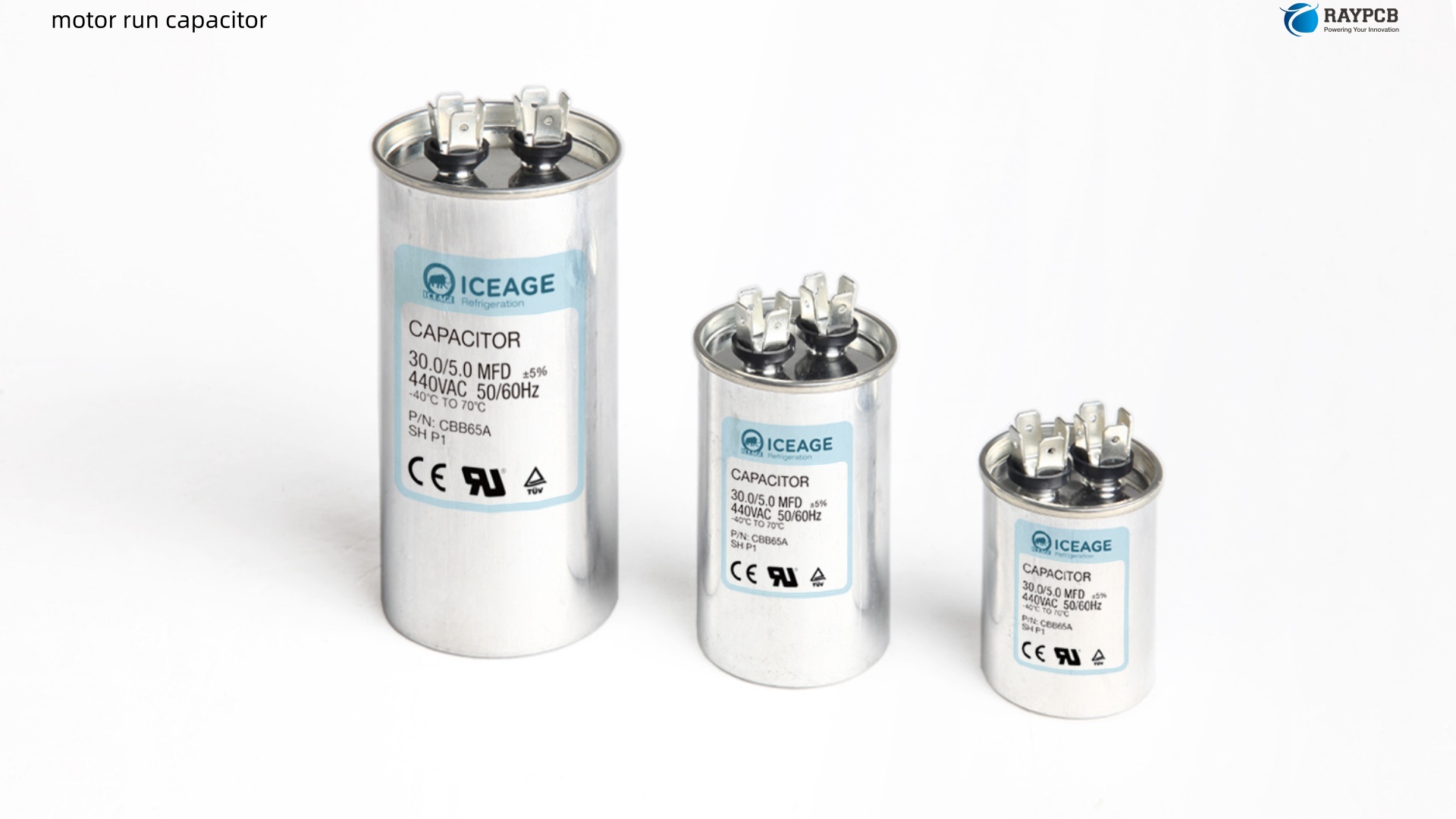
| Case | Metal cylinder or oval canister | Round most common; oval also available |
| Tolerance | ±5% to ±10% | Must match spec within 5–10% |
Motor Start Capacitor vs Motor Run Capacitor: Head-to-Head Comparison
| Feature | Motor Start Capacitor | Motor Run Capacitor |
| Primary function | Boost starting torque | Maintain running efficiency |
| Time in circuit | Seconds (until ~75% speed) | Continuously while motor runs |
| Capacitance value | 70–1,200 µF (range) | 1.5–100 µF (fixed) |
| Construction | Aluminum electrolytic | Polypropylene film |
| Voltage ratings | 125 V, 165 V, 250 V, 330 VAC | 250 V, 370 V, 440 VAC |
| Duty rating | Intermittent | Continuous |
| Disconnection | Via centrifugal switch | Always in circuit |
| Case color | Typically black plastic | Typically metal, silver/gray |
| Value marking | Range (e.g., 88–108 µF) | Single value (e.g., 35 µF) |
| Can it replace the other? | Never — fails under continuous duty | Only in unusual circumstances; values too low |
| Failure mode | Catastrophic (blows top) | Gradual capacitance drop; sometimes bulge |
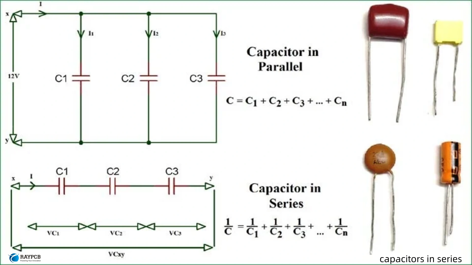
The Dual Run Capacitor: One Can, Two Jobs
In many HVAC systems — particularly air conditioner condensing units — you’ll find a dual run capacitor. This is simply two run capacitors sharing a single cylindrical can. The three terminals are labeled:
- C — Common
- HERM — Hermetically sealed compressor motor
- FAN — Condenser fan motor
A common example would be a 40+5 µF at 440 VAC dual capacitor: the 40 µF section serves the compressor, and the 5 µF section serves the fan motor. These are electrically independent inside the can; the only shared element is the common terminal and the physical housing. When one section fails, the entire dual capacitor is typically replaced, though it’s technically possible to replace a failed section with a separate run capacitor wired to match.
A 440 V rated capacitor can always substitute for a 370 V application, but never the reverse — voltage ratings must match or exceed the original.
Capacitor-Start vs Capacitor-Run Motor Types
The application tells you which capacitor arrangement is in use:
Capacitor-Start Motor (CS)
Uses only a start capacitor and runs on the main winding alone after the centrifugal switch opens. Delivers high starting torque but less efficient running performance. Common in compressors, pumps, and any application needing heavy load starts.
Capacitor-Run / Permanent Split Capacitor (PSC) Motor
Uses only a run capacitor, permanently connected. No centrifugal switch required. Lower starting torque but quieter, more efficient running. Common in direct-drive fans, small pumps, HVAC blower motors.
Capacitor-Start Capacitor-Run (CSCR) Motor
Uses both. The start capacitor delivers high starting torque; the centrifugal switch disconnects it once the motor reaches speed; the run capacitor remains in the circuit for efficient continuous operation. Most expensive and mechanically complex, but the best all-around performance. Used for demanding applications where both high starting torque and efficient continuous running are required.
Motor Type and Capacitor Configuration Summary
| Motor Type | Start Cap | Run Cap | Starting Torque | Running Efficiency |
| Capacitor-Start (CS) | Yes | No | High | Moderate |
| Permanent Split Cap (PSC) | No | Yes | Low-Moderate | High |
| Cap-Start Cap-Run (CSCR) | Yes | Yes | Very High | High |
| Split-Phase (resistance start) | No | No | Moderate | Low |
How to Size a Replacement Motor Run Capacitor
Getting the replacement wrong — even slightly — causes the rotor’s magnetic field to become uneven. The rotor hesitates at those uneven spots during each rotation, creating noise, increased power consumption, reduced output torque, and accelerated winding wear. Here’s the correct sizing process:
Step 1: Read the Motor Nameplate
Always start with the motor’s data tag or nameplate, not the old capacitor. The motor manufacturer tested specific capacitor values for that exact motor design. The nameplate may specify the run capacitor value directly. If not, check the motor manufacturer’s documentation.
Step 2: Match the Capacitance Value Exactly
For motor run capacitors, exact replacement is mandatory. The acceptable tolerance is ±5% to ±10%. Do not substitute a higher or lower value thinking it will “work close enough.” A wrong value disrupts the balance between main and auxiliary winding currents, causing hesitation and overheating.
Step 3: Match or Exceed Voltage Rating
Never install a lower voltage rating than the original. The common run capacitor voltage classes are 250 VAC, 370 VAC, and 440 VAC. A 440 V capacitor can replace a 370 V application but not vice versa. The voltage rating must meet or exceed the line voltage the motor will see.
Step 4: Verify with the Load Test Formula
If the original rating is unknown, you can calculate the correct µF value from live measurements:
µF = (Start Winding Amps × 2,652) ÷ Capacitor Voltage
Measure the amperage on the wire running from the capacitor to the start winding, and the voltage between the capacitor’s relevant terminals (HERM to C, or FAN to C for a dual cap). Plug those values in and compare to the installed capacitor’s rating. If it’s outside the ±10% range, replacement is warranted.
Motor Run Capacitor Sizing Reference Table
| Motor HP | Voltage | Typical Run Capacitor Value |
| 1/6 HP | 115 V | 3–5 µF |
| 1/4 HP | 115 V | 5–7.5 µF |
| 1/3 HP | 115 V | 7.5–10 µF |
| 1/2 HP | 230 V | 10–15 µF |
| 3/4 HP | 230 V | 15–20 µF |
| 1 HP | 230 V | 25–35 µF |
| 2 HP | 230 V | 35–50 µF |
These are general guidelines. Always verify against the motor’s nameplate or manufacturer documentation first.
How to Test a Motor Run Capacitor
Visual Inspection First
A failed or failing run capacitor often shows physical signs:
- Bulging or swollen sides/ends — internal pressure buildup; replace immediately
- Leaking oil (wet-fill types) — dielectric fluid escaping; replace immediately
- Blown pressure relief — safety interrupter has tripped; replace immediately
If the capacitor looks intact, proceed to electrical testing.
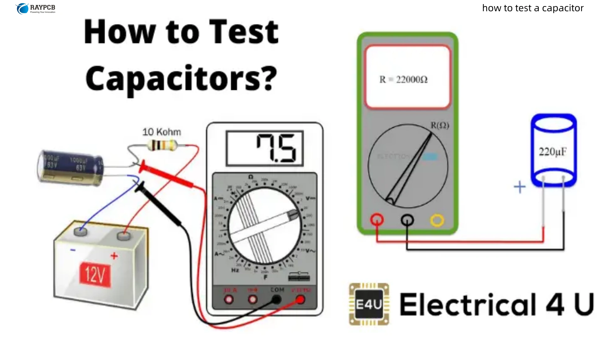
Testing with a Multimeter (Capacitance Mode)
- De-energize and discharge the capacitor — bridge the terminals briefly with a resistor (10–20 kΩ, 2W) or use a discharge tool. Never short directly.
- Set the multimeter to capacitance (µF) mode.
- Connect test leads to the capacitor terminals.
- Compare the reading to the rated value on the label.
- If the measured value is outside the specified ±5–10% tolerance, replace the capacitor.
Testing Under Load (More Accurate)
The load test using the formula above (amps × 2,652 ÷ voltage) gives a more realistic reading because it measures the capacitor’s actual behavior under operating conditions rather than just static capacitance. A capacitor can pass a static test but still underperform under load, particularly in aging units.
Signs of a Failing Motor Run Capacitor
Pay attention to these symptoms — they often show up well before complete failure:
| Symptom | Likely Cause |
| Motor hums but won’t start | Start cap failed or run cap too weak to assist |
| Motor runs but draws high current | Run cap value dropped; magnetic field unbalanced |
| Motor runs hot | Inefficient field from weak cap; windings overcompensating |
| Noisy operation (vibration, buzzing) | Rotor hesitating at uneven magnetic field spots |
| Motor turns off unexpectedly | Overload protection tripping from excess current |
| Slow acceleration to full speed | Weak or failed start cap |
Motor Run Capacitor Lifespan and Failure Causes
A quality run capacitor has a design life of 30,000 to 60,000 operating hours. Factory-installed capacitors in highly cost-competitive products sometimes have design lives as short as 1,000 hours. Three factors dramatically shorten run capacitor life:
Heat is the primary killer. Every 10°C rise above the capacitor’s rated operating temperature roughly halves its service life. Motors running in hot environments, poorly ventilated enclosures, or next to heat-generating components will eat through run capacitors far faster than expected.
Overvoltage has an exponential effect. Running a 370 V capacitor on a line that regularly spikes to 420 V will degrade the dielectric far faster than normal aging predicts. Always use the 440 V class capacitor when line voltage stability is uncertain.
Motor faults upstream can overload the capacitor. If motor windings are beginning to fail, current through the capacitor rises above its rated value, accelerating thermal aging. A string of run capacitor failures in a motor that otherwise seems fine is a warning sign to check the motor windings closely.
Useful Resources for Motor Capacitor Selection and Design
| Resource | Type | Link |
| Capacitor Industries – Run vs Start Capacitor Guide | Technical PDF | capacitorindustries.com PDF |
| TemcoIndustrial – Motor Capacitor FAQ | Technical Guide | temcoindustrial.com |
| TemcoIndustrial – Run Capacitor Selection Guide | Selection Guide | temcoindustrial.com |
| HVAC School – Testing Run Capacitors Under Load | Practical Guide | hvacrschool.com |
| Wikipedia – Motor Capacitor | Reference Overview | en.wikipedia.org |
| InspectApedia – Motor Capacitor Selection Guide | Diagnostic Guide | inspectapedia.com |
| DigiKey TechForum – Start vs Run Capacitors | Forum/Technical Reference | forum.digikey.com |
| IC-Online – Capacitor Sizing Chart Guide | Sizing Reference | ic-online.com |
Frequently Asked Questions About Motor Run Capacitors
Q1: Can I use a motor start capacitor as a motor run capacitor in an emergency?
No. A start capacitor is built for intermittent duty — seconds at a time. Leaving it energized continuously will cause it to overheat and fail catastrophically, often destroying the motor winding in the process. The direction is one-way only: a run capacitor can theoretically substitute for a start capacitor in unusual circumstances if the capacitance and voltage ratings match, but a start capacitor can never substitute for a run capacitor under continuous operation.
Q2: What happens if I install the wrong µF value motor run capacitor?
The motor’s magnetic field becomes unbalanced. The rotor will hesitate at uneven spots during each rotation, causing audible noise, elevated current draw, reduced output torque, and overheated windings. The motor will still run, but it will run poorly and its lifespan will be shortened. Both over-sized and under-sized capacitors cause problems. The correct value is the one specified by the motor manufacturer — not the nearest available standard value.
Q3: Can I use a 440 V run capacitor to replace a 370 V run capacitor?
Yes, in terms of voltage rating, a 440 V capacitor is a safe substitute for a 370 V application. The higher voltage rating simply means the dielectric can withstand more stress, which never hurts. The reverse — using a 370 V capacitor in a 440 V application — is not acceptable and will shorten the capacitor’s life and risk failure. The capacitance value (µF) must still match the motor specification exactly regardless of which voltage class you use.
Q4: My motor run capacitor reads within tolerance on a multimeter but the motor is still running hot. Could the capacitor still be the problem?
Yes. A static capacitance test measures the capacitor at low voltage with no AC stress. A capacitor that reads correctly off-circuit can still have elevated ESR (equivalent series resistance) or poor high-frequency characteristics that cause it to underperform under operating conditions. The load test formula — amps × 2,652 ÷ capacitor voltage = µF — gives a much more accurate picture of actual performance under load. If the under-load value diverges significantly from the static test, the capacitor is degraded and should be replaced even if the static reading looks fine.
Q5: How often should a motor run capacitor be replaced as preventive maintenance?
There’s no universal interval because operating conditions vary so much. In a climate-controlled indoor environment with a well-ventilated motor, a quality run capacitor may last a decade or more. In a hot outdoor HVAC condensing unit running most of the summer, life can be considerably shorter. A practical approach is to test run capacitors annually with a calibrated multimeter. If the value has dropped more than 5–10% below the rated value, replace it before it causes a motor fault. After the sixth or seventh season of service in a demanding HVAC application, proactive replacement is cheaper than an emergency service call.
The Bottom Line
The motor start capacitor and the motor run capacitor share a body style and a unit of measurement. That’s roughly where the similarity ends. The start capacitor is a short-burst electrolytic that lives in the circuit for seconds, gets switched out by a centrifugal switch, and must never be left energized. The motor run capacitor is a polypropylene film component that runs continuously at line voltage for the entire service life of the motor, keeping the auxiliary winding phase-shifted and the magnetic field balanced.
Getting replacement right means matching the µF value exactly for run capacitors, matching or exceeding voltage ratings for both, never substituting a start cap for a run cap, and testing under load rather than relying only on a static multimeter reading. Do those things and motor capacitor failures become predictable, diagnosable, and cheap to fix — instead of surprises that take the motor with them.