Kingboard PCB: Complete Guide to Types, Materials & Applications [2026]

Kingboard PCB materials explained by engineers, for engineers. This complete 2026 guide covers all FR-4, CEM-1, CEM-3 laminate grades (KB-6160, KB-6167, KB-616XF), surface finishes, Tg ratings, and real-world applications โ€” with datasheets and a buyer’s selection framework.

If you’ve spent any time sourcing PCB laminates, you’ve almost certainly crossed paths with Kingboard PCB materials โ€” probably without even realizing it. Kingboard Laminates Holdings Ltd. is one of the world’s largest copper-clad laminate (CCL) producers, and their materials quietly sit inside everything from industrial control boards to automotive ECUs to everyday consumer electronics. Yet surprisingly, a lot of engineers still pick Kingboard PCB laminates based on price alone without fully understanding what differentiates one grade from another. That’s a mistake that can cost you rework cycles and field failures down the line.

This guide breaks down the full Kingboard PCB lineup โ€” laminate grades, surface finishes, real-world applications, and how to make the right material call for your next design.

What Is Kingboard PCB? A Quick Company Background

Kingboard Holdings Limited (SEHK: 148), formerly Kingboard Chemical Holdings, is a Hong Kong-headquartered multinational that established its first laminate manufacturing plant in Shenzhen in 1988. Today, the group operates more than 60 manufacturing facilities across China and Thailand, covering the full vertical supply chain โ€” from glass yarn and copper foil production right through to finished printed circuit boards.

The PCB materials business is handled by Kingboard Laminates Holdings Ltd., a separately listed subsidiary that specializes in glass epoxy laminates, paper laminates, and CEM (Composite Epoxy Material) laminates. On the finished PCB side, their subsidiary Elec & Eltek International (acquired in 2004) manufactures high-density interconnect (HDI) and backplane PCBs of up to 50 layers for major global OEMs.

What makes Kingboard PCB materials a go-to for manufacturers is a combination of consistent batch quality, globally scalable supply, competitive pricing, and broad IPC/UL compliance. They aren’t a boutique material supplier โ€” they’re a volume workhorse, and that’s exactly what most production engineers need.

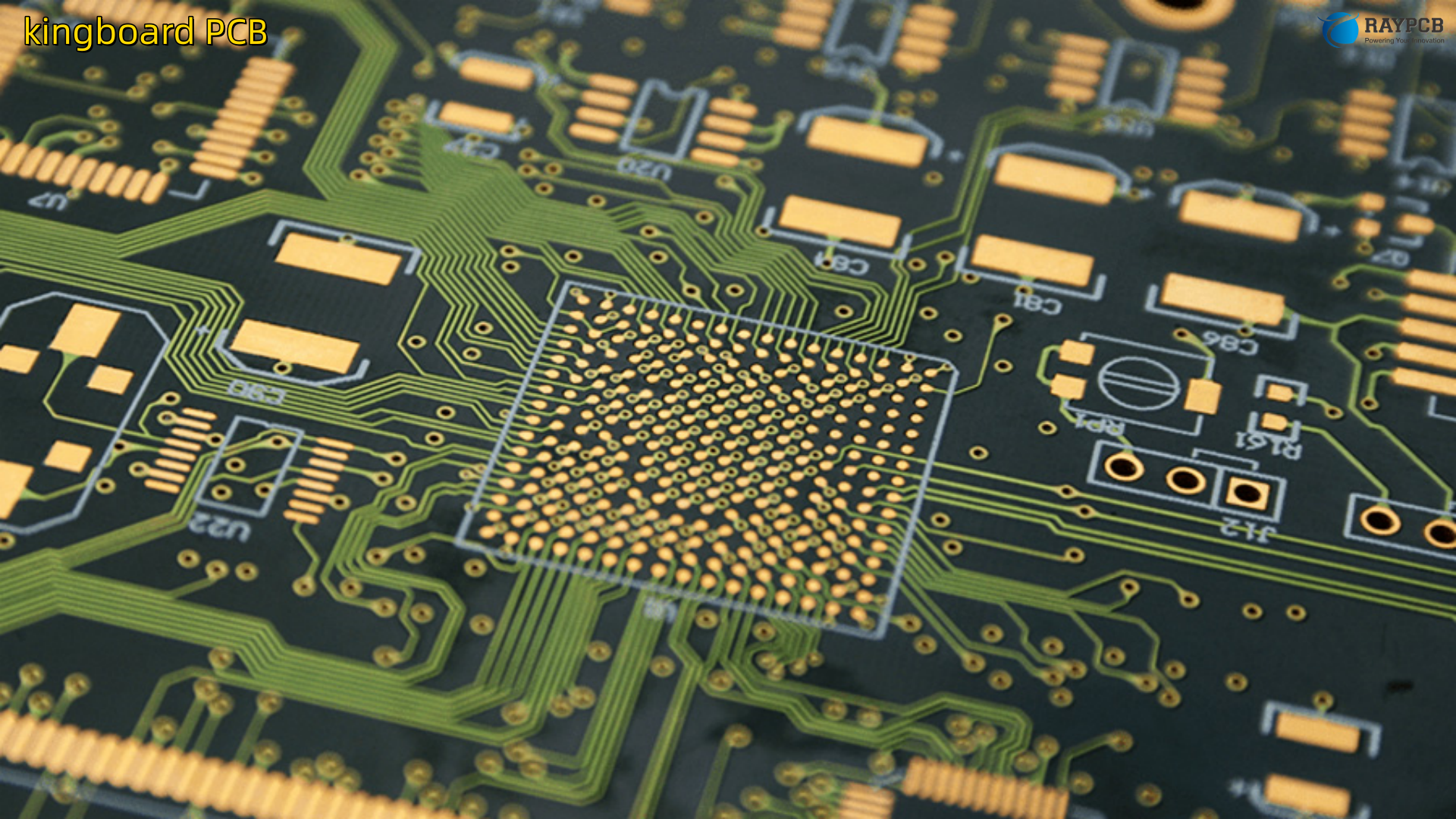
Understanding Kingboard PCB Laminate Grades

This is where most engineers need to slow down and pay attention. “Kingboard PCB” isn’t a single product โ€” it’s a family of laminate materials, each with its own resin chemistry, reinforcement system, and performance profile. Picking the wrong grade is one of the most common and avoidable root causes of PCB reliability failures.

FR-4 Kingboard PCB Laminates

FR-4 is the backbone of the Kingboard PCB lineup and the most widely used class of CCL in the industry. The designation “FR” stands for Flame Retardant, and these laminates comply with the UL94 V-0 flammability standard. The reinforcement is woven E-glass fabric impregnated with epoxy resin, giving FR-4 an excellent balance of mechanical strength, electrical insulation, and thermal performance.

Kingboard produces multiple FR-4 grades under their KB-6000 series. The most common ones you’ll encounter in fabrication are:

Kingboard GradeTg (ยฐC)Key FeatureTypical Application
KB-6160135Standard FR-4, IPC-4101E/21 compliant, excellent dimensional stabilityConsumer electronics, industrial PCBs, 4โ€“8 layer boards
KB-6160C135Lead-free assembly compatibleRoHS-compliant products requiring lead-free soldering
KB-6160F135Filled resin, reduced Z-axis CTE (~3.8%)High-reliability multilayer boards
KB-6160LC135Low CTE via resin chemistry (not fillers)Boards where maintaining low Dk is also a priority
KB-6165150Mid-high Tg, improved thermal stabilityTelecom, servers, lead-free reflow
KB-6167170High Tg, low Z-axis expansionAutomotive, demanding multilayer stackups
KB-616XF~170Lead-free capable, excellent heat resistanceAutomotive ECUs, high-end computing

The KB-6160 is worth understanding in depth because it’s the most commonly specified Kingboard PCB laminate globally. It meets IPC-4101E/21 specifications, supports glass styles 1080, 2116, 3313, and 7628 prepregs (KB-6060 series), and comes in panel sizes of 37โ€ณร—49โ€ณ, 43โ€ณร—49โ€ณ, and 41โ€ณร—47โ€ณ. Copper options range from 1/3 oz to 3 oz, including both high-temperature elongation (HTE) and reverse-treated copper options.

The KB-6167 steps things up considerably โ€” it’s built to withstand a Tg of 170ยฐC and features notably low Z-axis expansion, which matters enormously in thick multilayer boards where thermal cycling can crack plated through-holes. The UL94 V-0 flammability rating is retained across all these grades.

For applications demanding lead-free soldering compatibility with added thermal headroom, KB-616XF is the grade of choice. It’s widely used in automotive and high-end computing applications where the board sees aggressive temperature profiles during assembly and service.

CEM-1 Kingboard PCB Laminates

CEM-1 laminates use a paper core impregnated with epoxy resin, with outer surface plies of epoxy/glass. Kingboard’s KB-5150 is the flagship CEM-1 product. It offers many of the advantages of full glass laminates at pricing closer to paper-based boards โ€” making it a cost-effective choice for single-sided boards in consumer appliances and cost-sensitive electronics.

One practical advantage of CEM-1 is its punching processability. The paper core punches cleanly, which suits high-volume, single-sided PCB production without the need for routing. CEM-1 is not suitable for multilayer boards, though โ€” the paper core limits via drilling quality and electrical performance in complex stackups.

PropertyCEM-1 (KB-5150 Series)Notes
Inner CorePaper/epoxyLower cost than full glass
Outer PliesGlass/epoxyImproved surface finish
PunchingExcellent (45โ€“70ยฐC)Suitable for mass production
Humidity ResistanceGoodKB-5150H is enhanced variant
Layer CountSingle-sided primarilyNot recommended for multilayer

CEM-3 Kingboard PCB Laminates

CEM-3 is essentially a step up from CEM-1 and a step below full FR-4. The core uses non-woven glass mat (glass felt) impregnated with epoxy, with woven glass plies on both surfaces. This gives CEM-3 better performance than CEM-1 in double-sided applications while maintaining better punching processability than FR-4.

The trade-off compared to FR-4 is thickness accuracy โ€” CEM-3’s glass mat core is structurally looser than woven glass fabric, which means tighter thickness tolerances are harder to maintain. For designs with strict impedance control requirements, FR-4 remains the better choice.

FR-1 and FR-2 Kingboard PCB Laminates

Both FR-1 and FR-2 are paper-based phenolic resin laminates, commonly used for single-sided PCBs in low-cost, low-frequency consumer applications. These materials leave solder-friendly traces and are easy to stamp, making them popular for simple boards in toys, remote controls, and basic household appliances.

The key difference between FR-1 and FR-2 is their Tg value โ€” both sit around 130ยฐC, though FR-2 is slightly more commonly used in modern single-sided consumer electronics due to marginally better moisture resistance. Neither grade is appropriate for lead-free assembly or any application involving sustained elevated temperatures.

Kingboard PCB Surface Finishes Explained

The laminate grade is only half of the material specification. The surface finish applied to the bare copper dictates solderability, shelf life, component compatibility, and environmental compliance. Here’s how the main options compare on Kingboard PCB assemblies:

Surface FinishSolderable LifeCostBest ForLimitations
HASL12+ monthsLowThrough-hole, standard SMTUneven surface, not for fine-pitch
Lead-Free HASL12+ monthsLow-mediumRoHS-compliant standard boardsSlightly rougher surface vs. HASL
ENIG12 monthsHighFine-pitch SMT, BGA, gold wire bondingBlack pad risk if process controlled poorly
Immersion Tin6โ€“12 monthsMediumFlat surface, press-fit connectorsTin whisker risk if not stored correctly
Immersion Silver6โ€“12 monthsMediumFine-pitch, RF boardsTarnishes on air exposure โ€” storage critical
OSP3โ€“6 monthsLowSingle-reflow, cost-sensitive productionLimited shelf life, not for rework

HASL remains the most widely used finish on Kingboard PCB production because of its low cost and robust solderability. However, for anything with BGAs, fine-pitch QFPs (0.5 mm pitch and below), or SMD passives smaller than 0402, ENIG’s flat, uniform surface is the professional choice.

Immersion Silver is worth considering for RF and high-frequency boards โ€” it offers excellent electrical conductivity and a flat surface, but requires careful handling to prevent tarnishing. The solderability window of 6 to 12 months means you need to manage your inventory accordingly.

Key Technical Properties of Kingboard PCB Materials

Engineers who’ve been burned by material failures know that the spec sheet matters. Here are the critical parameters to understand when evaluating any Kingboard PCB laminate:

Glass Transition Temperature (Tg)

Tg is the temperature at which the resin transitions from a rigid, glassy state to a softer, rubbery state. Below Tg, the material behaves predictably. Above it, CTE (coefficient of thermal expansion) increases dramatically โ€” especially in the Z-axis โ€” which stresses plated through-holes and can cause barrel cracking. For lead-free assembly (peak reflow temperatures of 245โ€“260ยฐC), specifying a material with Tg โ‰ฅ 150ยฐC is generally recommended.

Dielectric Constant (Dk) and Dissipation Factor (Df)

For standard Kingboard FR-4 grades like KB-6160, Dk is approximately 4.3โ€“4.7 at 1 MHz. This is fine for digital boards up to a few hundred MHz, but becomes problematic at GHz-range signal speeds where Dk variation causes impedance discontinuities and Df-driven signal loss. If you’re routing differential pairs above 1 GHz, you’re in high-frequency laminate territory โ€” consider Megtron, Rogers, or PTFE-based materials instead.

Z-Axis CTE

Standard FR-4 has a Z-axis CTE of around 50โ€“70 ppm/ยฐC above Tg. High-Tg grades and filled variants (like KB-6160F) can bring this down significantly. Low Z-axis CTE is critical for boards with small via aspect ratios, dense BGAs, and any design expected to undergo significant thermal cycling in the field.

Moisture Absorption

Standard FR-4 absorbs โ‰ค0.15% moisture at 23ยฐC over 24 hours per IPC-4101. This seems minor, but moisture absorption affects Dk and Df, degrades insulation resistance, and can cause steam-driven delamination during reflow. For high-humidity environments (marine, outdoor, industrial), select enhanced-moisture variants or ensure proper bake-out before assembly.

Kingboard PCB Applications by Industry

The broad portfolio of Kingboard PCB materials means they show up across virtually every electronics segment. Here’s where each grade tends to land in practice:

IndustryRecommended Kingboard GradeWhy
Consumer ElectronicsKB-6160, FR-2, CEM-1Cost-effective, adequate thermal performance
Industrial ControlsKB-6160, KB-6165Thermal stability, multilayer capability
AutomotiveKB-6167, KB-616XFHigh Tg, low Z-axis CTE, lead-free compatible
Telecom / ServersKB-6165, KB-6167High-layer count, lead-free reflow, signal integrity
Military / AerospaceKB-6160 (+ special qualification)Dimensional stability, IPC compliance
LED LightingCEM-1, FR-4 standardCost efficiency for simpler thermal paths
Power ElectronicsHigh-Tg FR-4 (KB-6167)Thermal cycling resistance

Automotive is the segment where Kingboard PCB material selection gets the most scrutiny. AEC-Q qualification requirements mean that selecting KB-616XF or KB-6167 is only the starting point โ€” you need to verify extended qualification testing data with Kingboard or your fabricator for safety-critical systems.

How to Choose the Right Kingboard PCB Material

After working with these materials across different design contexts, here’s the practical decision framework most engineers use:

Start with your thermal budget. What is the peak temperature this board will see during assembly? What is the maximum operating temperature in the field? If your reflow profile peaks at 260ยฐC (lead-free SAC305), you need Tg โ‰ฅ 150ยฐC โ€” reach for KB-6165 or higher.

Evaluate your layer count and via aspect ratio. Thick multilayer boards (8+ layers) with deep vias benefit from low Z-axis CTE materials like KB-6160F or KB-6167. Standard KB-6160 is adequate for 4โ€“6 layer designs with normal via geometry.

Consider your operating frequency. Standard Kingboard FR-4 works well below 500 MHz. Above that, Dk and Df start to matter. Beyond 2 GHz, you should be evaluating specialty materials rather than any standard FR-4.

Factor in environmental compliance. RoHS/REACH requirements mean lead-free soldering compatibility is increasingly mandatory. Ensure your chosen Kingboard grade carries the appropriate certifications.

Don’t over-specify. KB-6167 is excellent, but if your design is a simple 4-layer industrial control board with standard HASL finish and no lead-free requirement, you’re paying a premium for performance you don’t need. KB-6160 will serve you well.

Certifications and Quality Standards

Kingboard PCB laminates carry a comprehensive set of industry certifications, which is one reason they’re trusted by fabricators worldwide:

  • UL94 V-0ย โ€” Flame retardancy certification across all FR-4 and CEM grades
  • IPC-4101C/Eย โ€” Qualification and performance specification for base materials
  • ISO 9001:2015ย โ€” Quality management system
  • RoHS / REACHย โ€” Environmental compliance for hazardous substances
  • CQCย โ€” China Quality Certification for domestic market compliance

Certification documents for specific grades are publicly available on the Kingboard Laminates website and are updated regularly as products receive renewals.

Useful Resources for Engineers

The following datasheets, directories, and databases are directly useful when specifying or evaluating Kingboard PCB materials:

  • Kingboard Laminates Official Siteย โ€” www.kblaminates.comย โ€” Product portfolio, certificates, and technical documents
  • KB-6160 Datasheet (PDF)ย โ€” AllDatasheet.com โ€“ KB-6160ย โ€” Full IPC specifications
  • PCB Directory โ€“ Kingboard Laminates Listingย โ€” PCBDirectory.comย โ€” Fabricators who stock Kingboard materials
  • IPC-4101 Standardย โ€” IPC.orgย โ€” The governing specification for PCB base materials
  • UL Product iQย โ€” iq.ul.comย โ€” Verify UL certification status by UL file number (Kingboard UL: E123995)
  • Kingboard CQC Certificatesย โ€” kblaminates.com/en/list/57.htmlย โ€” Updated certification list by product and plant

Frequently Asked Questions About Kingboard PCB

Q1: Is Kingboard PCB material equivalent in quality to Shengyi or ITEQ FR-4?

In the standard Tg range, Kingboard KB-6160 is broadly comparable to Shengyi S1141 and ITEQ IT-158 in terms of electrical and mechanical properties. All three meet IPC-4101 requirements. Kingboard tends to be slightly more competitive on price at high volume, while Shengyi is sometimes preferred in North American markets due to supply chain familiarity. For high-Tg applications, compare specific datasheets โ€” grades don’t map 1:1 between manufacturers.

Q2: Can I use Kingboard KB-6160 for lead-free assembly?

Standard KB-6160 has a Tg of 135ยฐC. While many fabricators use it successfully with lead-free SAC305 solder (peak ~260ยฐC), the margin above Tg is narrow. For better reliability, specify KB-6160C (lead-free compatible variant) or upgrade to KB-6165 (Tg 150ยฐC). The right answer depends on your thermal profile, layer count, and reliability target.

Q3: Where can I download Kingboard PCB datasheets?

The official source is www.kblaminates.com. Individual datasheets are also indexed on AllDatasheet.com and PCBDirectory.com. For the KB-6160, the datasheet covers thermal, mechanical, and electrical properties in line with IPC-4101E/21.

Q4: What is the difference between KB-6160 and KB-6167?

Both are FR-4 laminates, but KB-6167 has a significantly higher Tg (170ยฐC vs. 135ยฐC) and substantially lower Z-axis CTE. This makes KB-6167 the appropriate choice for thick multilayer boards, boards undergoing aggressive thermal cycling, or any application where plated through-hole reliability is critical. KB-6160 is the cost-effective general-purpose option; KB-6167 is the reliability-focused upgrade.

Q5: Are Kingboard PCB laminates RoHS compliant?

Yes. Kingboard’s FR-4 and CEM laminate grades comply with RoHS and REACH directives. Halogen-free variants are also available for markets with stricter environmental requirements. Always confirm the specific grade’s compliance documentation from the Kingboard certificate listing before finalizing a BOM for regulated markets.

Panasonic PCB Materials Explained: MEGTRON, FELIOS & XPEDION Series Guide

A PCB engineer’s guide to Panasonic PCB materials โ€” MEGTRON, FELIOS & XPEDION series explained with specs tables, application comparisons, and selection tips.

If you’ve been designing high-speed, high-frequency boards long enough, you’ve probably hit a wall with standard FR-4. The signal integrity falls apart at anything above a few gigahertz, the transmission losses stack up, and suddenly your carefully modeled stackup doesn’t perform the way it should in the real world. That’s the moment most engineers start looking at premium laminate materials โ€” and Panasonic PCB materials almost always come up in that conversation.

Panasonic’s Electronics Materials Business Division has spent decades developing some of the most recognized substrate brands in the industry. Whether you’re working on a 5G base station antenna, an AI data center backplane, automotive radar, or a compact flex assembly for mobile devices, there’s very likely a Panasonic PCB material engineered for that exact application. This guide breaks down every major series โ€” MEGTRON, FELIOS, XPEDION, HIPER V, and halogen-free solutions โ€” so you can make a well-informed material selection before your next design spin.

Why Panasonic PCB Materials Stand Apart from Standard FR-4

Standard FR-4 is cheap, widely available, and easy to fabricate. For most general-purpose electronics, it’s perfectly adequate. But once your design pushes above 1 GHz โ€” particularly into the 5G mmWave, 77 GHz automotive radar, or 100G+ networking territory โ€” FR-4’s dielectric constant (Dk) and dissipation factor (Df) become a serious liability.

Panasonic PCB materials address this by using advanced resin systems like polyphenylene ether (PPE), liquid crystal polymer (LCP), and specialized hydrocarbon compounds. These deliver significantly lower Dk and Df values, reduced transmission loss at high frequencies, better thermal stability under lead-free soldering conditions, and in many cases, environmental compliance (RoHS, REACH, halogen-free).

The tradeoff is cost and process complexity โ€” but for applications where signal integrity is non-negotiable, the engineering case is clear. Let’s go through each series in detail.

Overview of the Panasonic PCB Material Portfolio

Before diving into individual series, here’s a high-level view of where each Panasonic PCB material family fits:

SeriesTypePrimary Use CaseKey Strength
MEGTRONRigid multilayerHigh-speed networking, 5G, AI serversUltra-low transmission loss
XPEDIONRigid multilayerRF/wireless, automotive radar, 5G antennasLow RF propagation loss
FELIOSFlexibleMobile devices, automotive flex, mmWaveFlexible, low moisture absorption
HIPER VRigid multilayerAutomotive electronicsHigh heat resistance, reliability
Halogen-FreeRigid multilayerEnvironmental compliance applicationsRoHS/REACH compliant
ECOOLRigidLED lighting boardsHigh thermal conductivity

The MEGTRON Series: Setting the Standard for High-Speed Panasonic PCB Design

Among all Panasonic PCB materials, MEGTRON is the most widely referenced in high-speed digital design circles. Engineers working on 10G, 25G, 100G, 400G, and now 800G+ systems consistently specify MEGTRON as their go-to substrate. The reason is straightforward: no other commercially mainstream material offers a comparable combination of low loss, processability, and thermal reliability.

The entire MEGTRON lineup uses a PPE (polyphenylene ether) or hydrocarbon-blended resin system. Compared to standard epoxy (FR-4), PPE resin delivers a dramatically lower dielectric constant and loss tangent โ€” which is exactly what you need to maintain signal integrity over long backplane traces or dense multilayer stackups.

MEGTRON 2: Halogen-Free for General High-Speed Applications

MEGTRON 2 is the entry point of the MEGTRON family, designed for applications that need better-than-FR-4 performance but don’t require the extreme low-loss properties of MEGTRON 6 or 7. It’s halogen-free, lead-free compatible, and suitable for networking equipment including servers and routers, as well as automotive components and measuring instruments. Think of it as the “everyday workhorse” for engineers who need to step up from FR-4 without jumping straight into premium pricing.

MEGTRON 4: Large-Volume High-Speed Data Transmission

MEGTRON 4 (Laminate R-5725 / Prepreg R-5620) takes performance a step further with low transmission loss and high heat resistance specifically optimized for servers and routers handling large volumes of high-speed data. If you’re designing a mid-tier switching or storage platform where MEGTRON 6 might be over-specified, MEGTRON 4 is a practical middle ground worth evaluating.

MEGTRON 6: The Industry Reference for Signal Integrity Engineers

MEGTRON 6 (Laminate R-5775 / Prepreg R-5670) is arguably the most widely used advanced PCB laminate in the world for high-speed multilayer boards. It uses PPE resin as the matrix with high-frequency ultra-low profile copper foil (H-VLP), giving it transmission loss performance that approaches PTFE-based materials while being significantly easier and cheaper to process.

Here’s the critical practical advantage for fabricators: MEGTRON 6 processes very similarly to standard FR-4. It doesn’t require the plasma treatment that PTFE demands for through-hole plating, and solder mask processes are standard. For high-layer-count boards, this translates into meaningfully better yield and lower cost compared to PTFE alternatives.

MEGTRON 6 Key Electrical Properties:

PropertyValueCondition
Dielectric Constant (Dk)3.34@1 GHz
Dissipation Factor (Df)0.002@1 GHz
Thermal Decomposition Temp (Tg)185ยฐCโ€”
Z-axis CTE45 ppm/ยฐCโ€”
Moisture AbsorptionLowStandard conditions
Lead-free Solder CompatibilityYesโ€”
Environmental ComplianceRoHSโ€”

The MEGTRON 6 family includes several sub-grades: MEGTRON 6(G), MEGTRON 6(K), and MEGTRON 6(N). The (N) variant uses low-dielectric-constant glass cloth, giving it further reduced Dk for the most demanding impedance-controlled designs, such as ultra-high-layer-count boards for mainframes and IC testers. MEGTRON 6 is the right pick for 10โ€“25 Gbps networking equipment, high-end servers and routers, switches, optical networks, high-frequency test instruments, and 5G base station hardware.

MEGTRON 7: Ultra-Low Loss for Supercomputers and High-End Infrastructure

MEGTRON 7 (R-5785) pushes the performance envelope further with the lowest propagation delay in the MEGTRON lineup. It’s designed for applications where MEGTRON 6 simply isn’t enough: supercomputers, high-end routers, enterprise-grade ICT infrastructure, and high-end antenna systems. MEGTRON 7 is also the first Panasonic PCB material to be qualified for use with the European Space Agency (ESA), a testament to the thermal and electrical reliability Panasonic has achieved with this material.

MEGTRON 8: Built for the 800G and AI Era

MEGTRON 8 (R-5795U) is Panasonic’s latest generation laminate, representing a significant leap forward from MEGTRON 6 and 7 platforms. It’s specifically engineered for next-generation high-speed communication network equipment โ€” the AI server clusters, 800G optical networking gear, probe cards, semiconductor test equipment, and optical transmission platforms that are defining the current electronics landscape.

MEGTRON Series Comparison at a Glance:

ModelLaminate GradeKey Target ApplicationPerformance Level
MEGTRON 2โ€”Automotive, general networkingGood
MEGTRON 4R-5725Servers, routers (mid-tier)Better
MEGTRON 6R-5775 / R-5775(N)5G, AI, high-layer networkingExcellent
MEGTRON 7R-5785Supercomputers, ESA-qualifiedOutstanding
MEGTRON 8R-5795U800G, AI data centers, test equip.Best-in-class

The XPEDION Series: Panasonic PCB for RF and Automotive Wireless Applications

While MEGTRON dominates the high-speed digital space, the XPEDION series targets a different challenge: low propagation loss in the radio frequency range. If you’re designing RF multilayer boards for 5G antennas, base station power amplifiers, automotive millimeter-wave radar (77 GHz), or ADAS sensor platforms, XPEDION is Panasonic’s answer.

XPEDION materials are optimized for large-capacity, high-speed transmission of high-frequency RF signals. They’re halogen-free and, critically, they support standard multilayer PCB processing โ€” an important advantage over PTFE substrates that require special handling.

XPEDION 1: The Benchmark for Low-RF-Loss Multilayer Boards

XPEDION 1 (R-5515X / R-5515) is halogen-free with ultra-low transmission loss in the RF range and an operating temperature ceiling of 200ยฐC. It’s the primary choice for automotive antenna systems, 5G base station antenna modules, and automotive millimeter-wave radar boards. XPEDION 1 directly reduces PCB process cost compared to PTFE materials while maintaining the RF performance needed for demanding wireless applications.

XPEDION T1: Adding Thermal Management to the RF Equation

XPEDION T1 (R-5575X / R-5575) adds a critical dimension that XPEDION 1 doesn’t prioritize: high thermal conductivity (0.60 W/mยทK). With a Tg of 245ยฐC (DMA), XPEDION T1 is engineered for power-intensive RF applications where heat management is as important as signal performance. Target applications include base station power amplifier boards, small cell systems, and automotive millimeter-wave radar antenna modules where both RF integrity and thermal dissipation are non-negotiable requirements.

XPEDION Series Comparison:

ModelGradeDk (@10 GHz)Df (@10 GHz)Thermal ConductivityTgKey Application
XPEDION 1R-5515X~3.3Very LowStandard200ยฐC5G antenna, auto radar
XPEDION T1R-5575X3.60.0050.60 W/mยทK245ยฐCPower amplifier, small cell

The FELIOS Series: Flexible Panasonic PCB Materials for Mobile and Automotive

The FELIOS series is where Panasonic PCB engineering addresses flexible circuit boards. This is a completely different design environment from rigid multilayer โ€” space constraints, dynamic bending, high-density interconnects, and increasingly, high-frequency performance in a flexible form factor. FELIOS materials are primarily aimed at mobile products and automotive flex applications, and they come in two distinct variants with very different engineering approaches.

FELIOS FRCC: Resin Coated Copper Foil for Thin, Dense Flex Boards

FELIOS FRCC is built around a resin-coated copper foil (RCC) construction โ€” a deliberate choice that simplifies the manufacturing process while enabling thinner, higher-density flexible PCBs. It’s halogen-free, and its core applications are HDI boards and smartphones, where reducing layer thickness and maintaining fine pitch are the design imperatives. FELIOS FRCC has a dielectric constant of 4.4 and is rated for signal frequencies up to 1 GHz, with a high Tg of 173ยฐC that provides good reliability under reflow conditions and elevated temperatures.

FELIOS LCP: Liquid Crystal Polymer for High-Frequency Flex Applications

FELIOS LCP is a more technically specialized material, built from specialty pure LCP (Liquid Crystal Polymer) film. LCP is increasingly important in modern electronics because it offers something that most flexible materials can’t: stable electrical properties across a very wide frequency range, combined with extremely low moisture absorption.

For a flex PCB engineer, moisture absorption is not just an environmental concern โ€” it directly affects Dk stability. Materials that absorb moisture shift their dielectric constant in unpredictable ways, which is catastrophic for impedance-controlled flex designs in millimeter-wave or high-frequency RF applications. LCP’s inherently low moisture absorption eliminates this problem.

FELIOS LCP Key Advantages:

  • Ultra-low moisture absorption (inherent to LCP polymer structure)
  • Stable Dk and Df over a wide frequency range
  • High dimensional stability โ€” critical for fine-pitch manufacturing
  • Halogen-free construction
  • Suitable for 5G mmWave flexible antennas, automotive flex radar modules, and medical equipment

FELIOS Series Summary:

ModelConstructionDkTgMoisture AbsorptionKey Applications
FELIOS FRCCResin Coated Copper Foil4.4173ยฐCLowHDI boards, smartphones
FELIOS LCPLiquid Crystal Polymer filmVery low (stable)HighUltra-lowmmWave flex, auto radar flex, medical

The HIPER V Series: Panasonic PCB for Automotive Electronics Reliability

HIPER V is Panasonic’s dedicated series for automotive multilayer circuit boards โ€” a market with its own unique set of requirements around thermal cycling, vibration resistance, long-term reliability, and AEC-Q grade compliance. Automotive electronics live in harsh environments far beyond the controlled conditions of a data center, and the substrate must perform reliably across temperature extremes, moisture exposure, and extended service lifetimes.

HIPER V materials offer higher heat resistance compared to standard automotive substrates and are designed to meet the demanding reliability standards that automotive Tier 1 suppliers and OEMs require. Applications span the full automotive electronics spectrum: powertrain control modules, ADAS processing boards, infotainment systems, and increasingly, the high-voltage power electronics in EV platforms.

Halogen-Free Panasonic PCB Materials: Environmental Compliance Without Performance Sacrifice

Environmental regulations have been tightening across the electronics industry for years. RoHS (Restriction of Hazardous Substances) and REACH directives, along with IPC and JPCA halogen-free standards (Cl โ‰ค 900 ppm, Br โ‰ค 900 ppm, Cl+Br โ‰ค 1500 ppm), have pushed material suppliers to develop alternatives to traditional brominated flame retardants.

Panasonic’s halogen-free lineup spans multiple series. MEGTRON 6 (R-5375) and FELIOS FRCC are leading examples of halogen-free Panasonic PCB materials that meet international environmental requirements without sacrificing the electrical and mechanical performance engineers depend on. These materials behave similarly to standard FR-4 in terms of processability while eliminating the toxic gas concerns associated with halogen-containing materials during manufacturing and in case of combustion.

It’s worth noting that most of the XPEDION and FELIOS series are halogen-free by design โ€” Panasonic has clearly made environmental compliance a built-in requirement rather than an afterthought in their newer material development.

How to Select the Right Panasonic PCB Material for Your Design

Material selection is one of the most consequential early decisions in any PCB design project. Getting it wrong costs money in respins, fabrication delays, and signal integrity debug sessions that could have been avoided. Here’s a practical framework for narrowing down your Panasonic PCB material choice:

Step 1: Define Your Frequency and Data Rate Requirements

This is the primary filter. Different operating frequency ranges point to different material families:

Frequency / Data RateRecommended Panasonic PCB Material
Up to 1 GHzFELIOS FRCC, Halogen-free standard series
1โ€“10 GHzMEGTRON 4, MEGTRON 6
10โ€“25 Gbps (digital)MEGTRON 6, MEGTRON 6(N)
25โ€“56 Gbps (digital)MEGTRON 6, MEGTRON 7
56 Gbps+ / 800G+MEGTRON 8
RF / mmWave (5G, 77GHz radar)XPEDION 1, XPEDION T1, FELIOS LCP
Flex RF / Flex mmWaveFELIOS LCP
Automotive rigidHIPER V

Step 2: Assess Thermal Requirements

Do you need lead-free solder compatibility? High-temperature operation? Thermal management for power-intensive RF stages? Run through these questions:

  • Lead-free assembly: All MEGTRON grades from MEGTRON 2 onward support lead-free soldering.
  • High Tg for thermal cycling: MEGTRON 6 (Tg 185ยฐC), XPEDION T1 (Tg 245ยฐC), FELIOS FRCC (Tg 173ยฐC).
  • High thermal conductivity: XPEDION T1 at 0.60 W/mยทK is the standout for heat dissipation.

Step 3: Consider the Form Factor

Rigid multilayer: MEGTRON, XPEDION, HIPER V, Halogen-free. Flexible: FELIOS FRCC or FELIOS LCP depending on frequency requirements. Rigid-flex: Discuss hybrid stackup options with your fabricator โ€” FELIOS can often be combined with MEGTRON cores in rigid-flex designs.

Step 4: Environmental and Regulatory Compliance

Check whether your end product must comply with RoHS, REACH, or specific automotive environmental directives. If halogen-free is mandatory, confirm with your fabricator that the specific Panasonic grade is certified accordingly. Most modern MEGTRON, XPEDION, and FELIOS grades are halogen-free, but always verify with the datasheet.

Step 5: Fabrication Costs and Availability

MEGTRON 6 is widely stocked globally and offers excellent processability vs. PTFE at competitive pricing for a premium laminate. MEGTRON 7, MEGTRON 8, and FELIOS LCP command a higher cost and may have longer lead times โ€” factor this into your procurement planning.

Panasonic PCB Materials vs. Competing High-Speed Substrates

Engineers evaluating Panasonic PCB materials often compare them against other premium substrates. Here’s a simplified comparison:

ParameterPanasonic MEGTRON 6Rogers RO4350BPTFE (e.g., RT/Duroid)Standard FR-4
Dk (@10 GHz)~3.34~3.48~2.2~4.3โ€“4.5
Df (@10 GHz)~0.002~0.0037~0.0009~0.02
ProcessabilityFR-4-likeFR-4-likeRequires special processStandard
Lead-free CompatibleYesYesLimitedYes
Halogen-FreeYesNo (standard)Depends on gradeNo (standard)
Relative CostMedium-HighMedium-HighVery HighLow
Best ForHigh-speed digital, 5GRF/microwaveHigh-RF performanceGeneral purpose

MEGTRON 6’s biggest competitive advantage isn’t raw Df performance (PTFE materials can go lower) โ€” it’s the combination of low loss AND standard multilayer processability, which is a manufacturing and cost advantage that matters enormously in production volumes.

Real-World Applications of Panasonic PCB Materials Across Industries

To ground the technical specs in practical context, here’s where you’ll encounter Panasonic PCB materials in actual end products:

Telecommunications & Data Infrastructure: MEGTRON 6, 7, and 8 are found in 5G base stations, high-end routers and switches from major networking OEMs, AI server backplanes, optical transport equipment, and 800G Ethernet line cards.

Automotive Electronics: HIPER V in powertrain and ADAS control modules; XPEDION 1 and T1 in 77 GHz millimeter-wave radar front-end boards; FELIOS LCP in automotive flex antennas; MEGTRON 2 in networking gateway modules inside connected vehicles.

Aerospace and Defense: MEGTRON 7 has achieved ESA qualification, opening the door for space-grade PCB applications. Panasonic continues space exposure experiments to validate material durability under extreme conditions.

Consumer Electronics and Mobile: FELIOS FRCC is embedded in smartphones for HDI flex layers; FELIOS LCP enables mmWave antenna integration in high-end handsets.

Industrial and Medical: MEGTRON 6 and halogen-free series appear in precision measurement equipment, IC testers, and medical diagnostic platforms where signal accuracy and reliability are critical.

Useful Resources for Panasonic PCB Material Selection

These official and industry-respected resources will help you go deeper into Panasonic PCB materials for your specific design needs:

ResourceDescriptionLink
Panasonic Industrial โ€“ Circuit Board Materials (Global)Official product catalog with all seriesindustrial.panasonic.com
Panasonic Industrial North America โ€“ MEGTRON SeriesNA-specific MEGTRON product pages and distributor infona.industrial.panasonic.com
Panasonic Europe โ€“ Circuit Board MaterialsEU product portal and datasheet downloadsindustry.panasonic.eu
XPEDION Product Page (Official)XPEDION 1 and T1 full specs and datasheetsindustrial.panasonic.com/ww/products/pt/xpedion
Panasonic White Paper PortalTechnical papers on MEGTRON and other materials (registration required)na.industrial.panasonic.com
Cirexx โ€“ Panasonic PCB Materials GuideFabricator perspective on using Panasonic materialscirexx.com/panasonic-materials
IPC-4101 StandardSpecification for Base Materials for Rigid and Multilayer Boardsipc.org
JPCA-ES-01-2003Japanese standard for halogen-free PCB material classificationReferenced in Panasonic datasheets

Frequently Asked Questions About Panasonic PCB Materials

Q1. What is the difference between MEGTRON 6 and MEGTRON 8?

MEGTRON 6 is the established industry standard for 10โ€“25 Gbps high-speed multilayer boards and remains the most widely available Panasonic PCB material in this performance class. MEGTRON 8 is Panasonic’s next-generation material, purpose-built for 56 Gbps+ and 800G+ applications like AI server backplanes, optical transmission equipment, and next-generation probe cards. MEGTRON 8 delivers substantially lower transmission loss and better thermal reliability than MEGTRON 6, but comes at higher cost and may have more limited fabricator availability today.

Q2. Can FELIOS LCP be used in rigid-flex PCB designs?

Yes, but the design and fabrication require careful engineering. FELIOS LCP is inherently a flexible material optimized for flex and flex-rigid applications. In a rigid-flex board, LCP-based flex layers can be integrated with rigid cores โ€” sometimes MEGTRON-family materials โ€” to create hybrid stackups. This approach is used in advanced automotive radar modules and high-frequency antenna-in-package designs. Work closely with your fabricator to validate the lamination process and bonding layer compatibility.

Q3. Is Panasonic MEGTRON 6 halogen-free?

Yes. The MEGTRON 6 R-5375 and related grades meet the IPC and JPCA halogen-free standards (Cl โ‰ค 900 ppm, Br โ‰ค 900 ppm). It also complies with RoHS and REACH environmental directives. Always verify the specific grade’s datasheet because different sub-variants of MEGTRON 6 may carry different certifications.

Q4. How does Panasonic XPEDION compare to Rogers RO4000 series for 5G antenna boards?

Both XPEDION and Rogers RO4000 are strong candidates for 5G antenna applications. XPEDION is engineered specifically for RF multilayer applications with an emphasis on processability within standard multilayer workflows. Rogers RO4350B is widely used and well-characterized for single and multilayer microwave boards. The key distinction is that XPEDION T1 offers higher thermal conductivity (0.60 W/mยทK), making it preferable for power amplifier boards where heat management is critical alongside RF performance. For millimeter-wave automotive radar (77 GHz), XPEDION 1 is a strong candidate given its validated performance at those frequencies and halogen-free composition.

Q5. Where can I download datasheets for Panasonic PCB materials?

The primary source for official Panasonic PCB material datasheets is the Panasonic Industrial global product portal at industrial.panasonic.com. Each product series page includes downloadable data sheets and application notes. For North American customers, the Panasonic White Paper Pagoda at na.industrial.panasonic.com requires free registration but provides access to detailed technical papers. Distributors like Panasonic-authorized PCB material partners can also supply sample quantities and tech support for design-in evaluation.

Final Thoughts: Choosing the Right Panasonic PCB Material for Your Next Design

The depth and breadth of the Panasonic PCB material portfolio is genuinely impressive from an engineering standpoint. There are very few applications in modern electronics โ€” from 800G AI backplanes to flexible mmWave radar modules โ€” that can’t be addressed by one of the series covered here.

The practical takeaway for design engineers is this: start with your frequency and data rate requirements, cross-reference with your thermal and mechanical constraints, check environmental compliance requirements for your target market, and then engage your PCB fabricator early. Not every fab has equal experience with every Panasonic PCB material โ€” particularly FELIOS LCP and MEGTRON 8 โ€” and that fab relationship matters as much as material selection for achieving the performance you’ve modeled.

MEGTRON 6 remains the “safe default” for most high-speed digital designs if you’re not sure where to start. If you need RF performance for 5G antennas or automotive radar, start with XPEDION 1 or T1. If flex is in the picture and frequency matters, FELIOS LCP is worth the evaluation effort. And if you’re pushing into the 800G era, it’s time to have a serious conversation about MEGTRON 8.

ITEQ PCB Laminates: The Complete Guide to Materials, Specs & Applications (2026)

ITEQ PCB laminates explained โ€” full product range, specs, Dk/Df tables, IT-180A vs competitors, and how to choose the right material for your design.

If you’ve been specifying PCB materials for any length of time, you’ve almost certainly come across ITEQ PCB laminates on a fabricator’s approved vendor list. ITEQ Corporation has quietly grown into one of the most trusted names in high-performance copper-clad laminate (CCL) manufacturing, and for good reason โ€” their materials consistently deliver where standard FR-4 falls short. Whether you’re designing a 40-layer server backplane, an automotive ECU, or a 5G base station board, understanding the ITEQ PCB laminate lineup will save you from costly material re-qualifications down the road.

This guide covers everything a working engineer or procurement professional needs to know: ITEQ’s full product range, key electrical and thermal specs, head-to-head comparisons, application fit, stackup tips, and downloadable resources.

What Is ITEQ Corporation and Why Do Engineers Specify Their Laminates?

ITEQ Corporation was founded in April 1997 and is headquartered in Hsinchu County, Taiwan. The company focuses exclusively on high-performance copper-clad laminates and prepregs for the PCB industry. Unlike diversified chemical companies that produce laminates as one of many product lines, ITEQ treats laminate R&D as its core business โ€” and that focused approach shows up in material consistency and qualification data.

ITEQ operates manufacturing facilities in Taiwan, Wuxi (Jiangsu, China), and Dongguan (Guangdong, China), which matters for global supply chain planning. Their in-house technology center in Taiwan runs signal integrity labs, material characterization labs, and a failure analysis facility โ€” not common for laminate suppliers of their size.

From an engineer’s standpoint, what makes ITEQ PCB materials attractive is their broad portfolio coverage. You can spec a cost-competitive FR-4 for a consumer product and a ultra-low-loss material for a 400G switch fabric from the same qualified supplier, which simplifies AVL management at the fab level.

How ITEQ PCB Laminates Differ From Standard FR-4

This is the question most engineers ask first, and it’s worth answering directly. Standard FR-4 โ€” the default for most general-purpose PCB designs โ€” is a woven glass/epoxy laminate with a Tg typically around 130โ€“140ยฐC. It works perfectly well for low-frequency, low-layer-count designs running in benign thermal environments.

The problem is that modern electronics push far beyond those boundaries. Lead-free soldering alone demands reflow peaks near 260ยฐC, which starts to stress any material with a Tg below 170ยฐC. Add high-speed SerDes running at 56 Gbps or higher, automotive temperature cycling from -40ยฐC to +125ยฐC, and tight Z-axis expansion budgets for BGAs with 1,500+ vias, and standard FR-4 quickly becomes a liability.

ITEQ PCB laminates address these gaps through formulated resin systems โ€” multifunctional epoxies, phenolic-cured systems, and low-loss modified resins โ€” engineered specifically for high thermal reliability, controlled impedance, and CAF (Conductive Anodic Filament) resistance. The result is a portfolio of materials where each grade solves a specific engineering problem, rather than a one-size-fits-all solution.

The Complete ITEQ PCB Laminate Product Range

ITEQ organizes its laminate portfolio into several performance tiers. Here’s a practical breakdown of the main product families an engineer will encounter in real projects.

Standard and Mid-Tg FR-4 Series

These are the workhorses for cost-sensitive applications where standard FR-4 performance is adequate but a step up in reliability is preferred.

ModelTg (DSC)Key FeatureTypical Application
IT-140~140ยฐCConventional FR-4, good through-hole reliabilityConsumer electronics, memory modules, notebooks
IT-140G~140ยฐCHalogen-free version of IT-140Handheld devices, RoHS-critical consumer products
IT-158>150ยฐCMedium-Tg, CAF resistance, heavy copper compatibleNetworking, automotive, heavy copper boards
IT-600StandardGeneral purposeConsumer, automotive, communications

IT-140 is the entry point โ€” if a customer specifies standard FR-4 compatibility and budget is a primary driver, IT-140 gets the job done. IT-158 is where most automotive or networking engineers start when they need reliable CAF performance without paying premium pricing.

High-Tg Epoxy Series

This is ITEQ’s volume sweet spot for server, storage, and telecom designs. All materials in this group support 260ยฐC lead-free assembly.

ModelTg (DSC)Dk @ 1GHzDf @ 1GHzHalogen-FreeNotable Feature
IT-150GS>150ยฐC~4.0~0.012YesCAF resistance, server/storage
IT-168G1>170ยฐC~3.9~0.010YesAerospace thermal cycling
IT-170GRA1~180ยฐC<3.9<0.010YesLow mid-loss, 3S applications
IT-170GLE>170ยฐC~3.9~0.012YesAutomotive thermal cycling
IT-180~170ยฐC~4.0~0.013NoStandard-loss high-Tg flagship
IT-180Aโ‰ฅ175ยฐC~3.9~0.012NoLow Z-CTE, CAF resistance
IT-180GN>170ยฐC~3.9~0.011YesHalogen-free high-Tg
IT-200LK~200ยฐC~4.0~0.015NoExtreme thermal environments

IT-180A deserves special mention because it is probably the most widely specified ITEQ PCB material in the industry. Its combination of Tg โ‰ฅ175ยฐC, Z-axis CTE of ~2.7% (50โ€“260ยฐC), T260 >60 minutes, and CAF resistance makes it the standard choice for high-layer-count multilayer boards, BGA-heavy designs, and sequential lamination builds.

High-Speed / Low-Loss Series

As signal speeds crossed 25 Gbps per channel and are now pushing past 112 Gbps, the loss characteristics of standard epoxy laminates became unacceptably high. ITEQ’s low-loss and ultra-low-loss series address this directly.

ModelTg (DSC)Dk @ 10GHzDf @ 10GHzLoss CategoryApplication
IT-958G>170ยฐC~3.6~0.007Low-LossHigh-speed digital
IT-968~185ยฐC<3.8<0.005Ultra-Low-Loss100G/400G switches
IT-968SE>170ยฐC<3.8<0.005Ultra-Low-Loss + HFIoT, eco-conscious
IT-988GSE>170ยฐC~3.4~0.004Very-Low-LossmmWave, 5G

IT-968 is the material specification engineers land on for 100G and 400G high-speed switch designs. A Df below 0.005 at 10 GHz is critical when you’re running long traces on a 40+ layer backplane โ€” every tenth of a dB in insertion loss matters at those data rates.

Specialty and Halogen-Free Series

ModelKey FeatureTypical Use
IT-150DAVery high-Tg (~180ยฐC), excellent thermal stabilityAutomotive power modules, EV battery management
IT-150GHalogen-free, medium-TgGeneral HF compliance applications
IT-180ATCHigh-Tg with tight-tolerance coreSequential lamination HDI
IT-258GA3High thermal conductivityPower converters, solar inverters
IT-859GTAMetal-base, 3W/mK conductivityHigh-power LED, thermal management

Key ITEQ PCB Specifications Every Engineer Must Understand

Reading a laminate datasheet without context leads to poor material decisions. Here’s what each parameter actually means in a production environment.

Glass Transition Temperature (Tg)

Tg is the temperature at which the resin transitions from a rigid glassy state to a softer, rubbery state. Above Tg, Z-axis expansion accelerates significantly, which stresses plated through-holes and via barrels. ITEQ reports Tg by DSC (Differential Scanning Calorimetry) per IPC-TM-650 2.4.25.

Rule of thumb: For lead-free assembly (260ยฐC peak), target materials with Tg โ‰ฅ170ยฐC. For boards that will operate at sustained elevated temperatures (automotive under-hood, industrial), push toward Tg โ‰ฅ180ยฐC.

Decomposition Temperature (Td)

Td marks the temperature at which the laminate loses 5% of its weight due to chemical breakdown. ITEQ IT-180A, for example, has a Td of approximately 350ยฐC. A high Td is critical for boards that go through multiple reflow cycles โ€” each cycle erodes material integrity slightly, and a higher Td provides more margin.

Z-Axis Coefficient of Thermal Expansion (CTE)

This is the single most overlooked spec in material selection, and it causes more field failures than any other. Z-axis CTE determines how much a board expands vertically during thermal cycling. For a via barrel connecting outer layers on a 3mm-thick board, excessive Z-CTE creates fatigue cracking over thousands of thermal cycles. ITEQ IT-180A achieves Z-axis CTE of ~2.7% from 50โ€“260ยฐC โ€” among the best in the standard high-Tg class.

Dielectric Constant (Dk) and Dissipation Factor (Df)

For impedance-controlled designs, Dk determines trace width for a given target impedance. Lower Dk allows narrower traces, which matters for dense HDI layouts. Df determines how much signal energy is absorbed by the dielectric as heat โ€” this is insertion loss, and it becomes dominant at high frequencies. When running signals above 10 GHz, Df often matters more than Dk.

CAF Resistance

Conductive Anodic Filament (CAF) is an electrochemical failure mode where copper ions migrate along glass fiber-resin interfaces, forming conductive paths that cause shorts between adjacent vias. Fine-pitch designs with via-to-via spacings below 0.5mm are especially vulnerable. ITEQ PCB materials rated for CAF resistance โ€” IT-150GS, IT-158, IT-180A โ€” use modified resin systems that block this ionic migration pathway.

ITEQ PCB vs. Competing High-Tg Laminates: Head-to-Head Comparison

Engineers frequently need to justify material selection against alternatives. Here’s a practical comparison of ITEQ IT-180A against the most commonly specified alternatives:

ParameterITEQ IT-180AIsola 370HRShengyi S1000-2MPanasonic R-1755V
Tg (DSC)โ‰ฅ175ยฐC~180ยฐC~170ยฐC~175ยฐC
Td~350ยฐC~340ยฐC~340ยฐC~360ยฐC
Z-CTE (50โ€“260ยฐC)~2.7%~3.0%~3.5%~2.5%
Dk @ 1GHz~3.9~3.9~4.0~3.9
Df @ 1GHz~0.012~0.021~0.015~0.010
T260>60 min>60 min>30 min>60 min
CAF ResistanceYesYesPartialYes
Lead-Free Compat.260ยฐC260ยฐC260ยฐC260ยฐC
Halogen-FreeNoNoNoNo
Supply RegionAsia (strong)GlobalAsia (strong)Global

From a practical standpoint, ITEQ IT-180A is most competitive when your fab is in Asia โ€” Taiwan, China, or Southeast Asia โ€” where ITEQ’s supply chain is strongest and pricing is most aggressive. Isola 370HR remains the dominant choice for North American fabs with long qualification histories. Panasonic R-1755V edges out ITEQ on Df if you’re pushing into mid-loss signal speeds, but at a significantly higher cost.

Industry Applications of ITEQ PCB Laminates

Servers, Storage, and Switching Infrastructure

This is ITEQ’s home turf. The 3S market (Server/Storage/Switch) drove the development of materials like IT-150GS, IT-968, and IT-180A. High-layer-count backplanes (20โ€“50+ layers), BGA processors with fine-pitch via fields, and 100G/400G SerDes requirements all push standard FR-4 to failure. IT-968 in particular has become a go-to spec for hyperscale data center switch fabric designs where insertion loss budgets are razor-thin.

Automotive Electronics

Automotive is where ITEQ’s thermal cycling credentials matter most. Engine control units, ADAS radar modules, and EV battery management systems all endure temperature excursions from -40ยฐC to +125ยฐC (or higher in under-hood applications), thousands of cycles, and vibration. IT-150DA and IT-170GRA1 are the common choices here. Both deliver the thermal cycling stability that automotive OEM qualification processes demand, and both carry the necessary RoHS compliance documentation.

5G and Telecommunications Infrastructure

5G base station design requires materials that maintain stable Dk and Df across the 3.5 GHz, 26 GHz, and 39 GHz bands depending on sub-6 GHz or mmWave architecture. ITEQ IT-988GSE with Dk ~3.4 and Df ~0.004 at high frequency starts to compete in this space, though pure PTFE laminates from Rogers or Taconic remain dominant for strict RF front-end layers. A practical approach in 5G design is a hybrid stackup โ€” ITEQ IT-968 or IT-988GSE for critical RF signal layers, IT-180A or IT-170GRA1 for power and ground layers โ€” balancing cost against performance.

Aerospace and Defense

Aerospace applications demand materials with proven thermal shock resistance and long service life. IT-168G1 has earned a track record in avionics for its resistance to delamination under thermal cycling. IT-200LK, with a Tg of approximately 200ยฐC, targets extreme environments where sustained high temperatures are expected. Both materials typically require extensive qualification packages including TMA Tg confirmation, 500+ cycle thermal shock testing, and IPC-TM-650 salt spray per 2.6.14 for avionic certifications.

Medical Devices and Industrial Electronics

Medical-grade PCBs emphasize long-term reliability, dimensional stability, and materials with well-documented electrical properties for predictable behavior over product lifetimes measured in decades. IT-170GRA1 and IT-180A both see use in imaging equipment, patient monitoring systems, and industrial automation controllers where field failure is not an option.

How to Select the Right ITEQ PCB Laminate for Your Design

Material selection should follow engineering requirements, not just cost. Use this decision framework:

Design RequirementRecommended ITEQ PCB Material
Standard FR-4 replacement, cost-sensitiveIT-140 / IT-158
Lead-free assembly, multilayer, generalIT-150GS / IT-170GRA1
High-layer-count BGA, server boardsIT-180A
Automotive thermal cycling (-40 to +125ยฐC)IT-150DA / IT-170GLE
10โ€“30 Gbps high-speed digitalIT-958G
100G/400G switches, ultra-low-lossIT-968 / IT-968SE
5G mmWave RF layersIT-988GSE
Extreme thermal environments (>180ยฐC)IT-200LK
Halogen-free compliance requiredIT-140G / IT-150GS / IT-180GN
High-power thermal managementIT-258GA3 / IT-859GTA

When in doubt, request qualification test data directly from your laminate distributor. ITEQ maintains regional technical support teams who can provide application-specific guidance โ€” particularly valuable when qualifying a new material for an automotive or aerospace platform.

ITEQ PCB Stackup Design Tips From the Trenches

A few practical notes that save headaches during fabrication:

Prepreg storage matters. ITEQ specifies a shelf life of at least 3 months for prepreg stored below 20ยฐC and 50% relative humidity. Prepreg exposed to ambient humidity must be resealed and should be reconditioned for 12 hours in a controlled environment before use. Many field delamination issues trace back to prepreg moisture absorption, not the material itself.

IT-180A drilling parameters differ from standard FR-4. For 0.4โ€“1.0mm drills, ITEQ recommends stack heights of โ‰ค2 panels for 2โ€“6 layer boards and single-panel stacks for 8+ layer builds. Max hit count should be kept below 1,000. The standard FR-4 desmear parameters will not produce optimal via topography for IT-180A โ€” confirm desmear chemistry with your fab shop before releasing to production.

For sequential lamination HDI, use IT-180ATC. The tight-tolerance core version of IT-180A maintains dimensional stability through multiple press cycles, which is essential for buildup structures where registration tolerance stacks up with each lamination sequence.

Use ITEQ’s online stackup tool. ITEQ provides a web-based stack-up tool that pulls actual Dk and Df values from their materials database. This gives you more accurate impedance calculations than using nominal datasheet values, which can differ from production-lot actual values by ยฑ3โ€“5%.

Vacuum degas before pressing. For multilayer press runs, vacuum degassing stacks for 30 minutes before the heating cycle removes entrapped air and significantly reduces the risk of voiding, especially in designs with embedded cavities or complex prepreg configurations.

Useful Resources and Datasheets for ITEQ PCB Laminates

ResourceDescriptionLink
ITEQ Official WebsiteFull product portfolio, regional contacts, newsiteq.com.tw
ITEQ IT-180A Datasheet (PCBWay Mirror)Official IT-180A spec sheet with full test dataPCBWay PDF
ITEQ IT-180A Datasheet (Midwest PCB Mirror)Alternative mirror with Tapco tech support contactMidwestPCB PDF
IPC-4101 StandardBase material specification standard for laminatesIPC.org
IPC-TM-650 Test MethodsStandard test methods referenced in all ITEQ datasheetsIPC-TM-650
PCB-Directory ITEQ LaminatesSearchable database of all ITEQ laminate modelsPCB-Directory
ITEQ Stackup ToolWeb-based stackup builder using real ITEQ Dk/Df dataAvailable via ITEQ distributor portal
PCBInformation.com ITEQ ProfileIndependent ITEQ material overview with product notespcbinformation.com

5 FAQs About ITEQ PCB Laminates

Q1: What is the most commonly specified ITEQ PCB material for multilayer server boards?

ITEQ IT-180A is by far the most widely specified material for high-layer-count server and storage PCBs. Its combination of Tg โ‰ฅ175ยฐC, Z-axis CTE of ~2.7% (50โ€“260ยฐC), T260 >60 minutes, and strong CAF resistance makes it the benchmark material for BGA-intensive multilayer designs. It is also broadly available across Asian PCB fabricators with competitive pricing.

Q2: Is ITEQ IT-180A the same as IT-180?

No, they are distinct materials. IT-180 uses a standard-loss multifunctional epoxy system with a Tg of approximately 170ยฐC by DSC. IT-180A uses a phenolic-cured resin system with a higher Tg (โ‰ฅ175ยฐC), significantly lower Z-axis CTE, and better CAF resistance. IT-180A is the preferred choice for demanding multilayer and sequential lamination applications. Always confirm the exact model with your fabricator.

Q3: Can ITEQ PCB laminates pass 260ยฐC lead-free assembly?

Yes โ€” all ITEQ materials from the IT-150GS grade and above are designed to pass 260ยฐC lead-free reflow. IT-180A specifically achieves T260 >60 minutes and T288 >30 minutes per IPC-TM-650 2.4.24.1. This means the material can withstand multiple reflow cycles without delamination or measurable degradation, which is critical for complex assemblies that go through top and bottom reflow passes.

Q4: Which ITEQ PCB material should I use for 5G base station designs?

It depends on whether you’re designing sub-6 GHz or mmWave hardware. For sub-6 GHz base station boards, IT-968 or IT-170GRA1 typically delivers adequate loss performance with good thermal reliability. For mmWave front-end layers operating above 20 GHz, IT-988GSE offers Dk ~3.4 and Df ~0.004 at high frequency. In practice, most 5G board designs use hybrid stackups โ€” low-loss ITEQ material for RF signal layers and standard high-Tg ITEQ material for power and ground layers โ€” to manage cost without compromising insertion loss.

Q5: Are ITEQ PCB laminates halogen-free?

ITEQ offers both halogen-containing and halogen-free versions across their portfolio. Halogen-free options include IT-140G, IT-150G, IT-150GS, IT-170GRA1, IT-180GN, IT-968SE, and several others. These materials meet RoHS and WEEE compliance requirements and are free from chlorine and bromine above the threshold limits defined by IPC-4101 and IEC 61249-2-21. If halogen-free compliance is a customer or market requirement, confirm the specific model suffix with your laminate distributor โ€” not all variants of a base material grade are halogen-free.

C0G Capacitor (NP0): What It Is & When to Use It

Learn what a C0G capacitor (NP0) is, how it differs from X7R, and exactly when to use it in RF, timing, and precision circuits โ€” with tables, specs, and FAQs.

If you’ve spent any time sourcing components or reviewing a BOM, you’ve almost certainly run into the term C0G capacitor โ€” sometimes written as NP0 โ€” and wondered whether it actually matters which type you specify. The short answer from any seasoned PCB engineer: yes, it absolutely does. Choose the wrong dielectric and you can watch a timing circuit drift, an oscillator wander off frequency, or an RF filter’s response shift unexpectedly with temperature. This guide breaks down everything you need to know about the C0G capacitor, how it compares to the alternatives, and exactly when it belongs on your board.

What Is a C0G Capacitor?

A C0G capacitor is a type of multilayer ceramic capacitor (MLCC) that uses a Class I dielectric material. The “C0G” designation follows the EIA (Electronic Industries Alliance) standard coding system. The name might look strange at first โ€” that middle character is a zero, not the letter O โ€” but once you break it down, the code makes sense:

  • Cย = the significant figure of the temperature coefficient (in this case, 0 ppm/ยฐC)
  • 0ย = the multiplier (ร—1)
  • Gย = the tolerance on the temperature coefficient (ยฑ30 ppm/ยฐC)

Put it together and you get a capacitor whose capacitance changes by no more than ยฑ30 ppm per degree Celsius across the full operating range of โˆ’55ยฐC to +125ยฐC. That works out to less than ยฑ0.3% capacitance change across that entire span. For a passive component, that is exceptional stability.

C0G vs NP0 โ€” Are They the Same Thing?

Yes, C0G and NP0 refer to the same component. NP0 comes from the U.S. Military Standard (MIL-SPEC) naming convention, where the letters stand for Negative-Positive-Zero โ€” meaning the capacitance does not shift in either the negative or positive direction as temperature changes. C0G is the EIA equivalent. European datasheets often print it as NPO (with a letter O), but the correct rendering uses a zero. Both terms refer to the same Class I ceramic dielectric, and you can use them interchangeably when ordering or specifying parts.

How C0G Capacitors Are Made

Class I ceramic capacitors like C0G use non-ferroelectric (paraelectric) formulations for their dielectric material, primarily based on strontium zirconate (SrZrOโ‚ƒ) or titanium dioxide (TiOโ‚‚), with various dopants added to fine-tune the temperature coefficient. Modern C0G formulations often incorporate neodymium, samarium, and other rare earth oxides. The non-ferroelectric nature of the material is the key: it does not polarize the way barium titanate (the basis for X7R and X5R) does, which is exactly what gives C0G its near-zero voltage coefficient and outstanding aging characteristics.

Key Electrical Characteristics of C0G Capacitors

Understanding what makes a C0G capacitor tick helps you know where to deploy it and where a cheaper alternative will do just fine.

ParameterC0G / NP0X7RX5RY5V
Dielectric ClassClass IClass IIClass IIClass II
Temperature Rangeโˆ’55ยฐC to +125ยฐCโˆ’55ยฐC to +125ยฐCโˆ’55ยฐC to +85ยฐCโˆ’30ยฐC to +85ยฐC
Capacitance Change vs Tempยฑ30 ppm/ยฐC (< ยฑ0.3%)ยฑ15%ยฑ15%+22% / โˆ’82%
Voltage CoefficientNoneSignificantSignificantSevere
AgingNoneYesYesYes
Typical Capacitance Range0.5 pF to ~100 nFUp to 10 ยตF+Up to 47 ยตF+Up to 100 ยตF+
Typical Toleranceยฑ0.5 pF, ยฑ1%, ยฑ2%, ยฑ5%ยฑ10%, ยฑ20%ยฑ10%, ยฑ20%ยฑ20%
Piezoelectric EffectNonePresentPresentPresent
Relative CostHigherMediumMediumLow
Package Size for Same ValueLargerMediumSmallerSmallest

Temperature Stability

Capacitance drift or hysteresis for C0G ceramics is negligible at less than ยฑ0.05%, versus up to ยฑ2% for film capacitors. Typical capacitance change over the service life of a C0G part is less than ยฑ0.1% โ€” one-fifth that shown by most other dielectrics. For engineers working on products that need to maintain spec over years of field use across wide temperature swings, that is not a trivial advantage.

No Voltage Coefficient

This one trips up a lot of engineers who are used to working only with X7R or X5R. A critical warning with Class II capacitors: they lose capacitance as DC voltage is applied. A 10 ยตF X7R capacitor rated for 16 V might only act like a 2 ยตF capacitor when 12 V is applied. The C0G capacitor has essentially no voltage coefficient. The value you see on the datasheet is the value you get, regardless of what DC bias is sitting across it.

No Aging

Ferroelectric materials undergo domain reorientation over time, which causes Class II capacitors to slowly lose capacitance after manufacture. C0G has no such aging mechanism. C0G formulations show no aging characteristics. This is particularly important for applications in medical devices, industrial instrumentation, and aerospace โ€” anywhere you need performance to remain consistent years after production.

No Piezoelectric Effect

Class 2 caps exhibit piezoelectric behavior that can cause them to function as both microphones (converting sound into electrical noise) and buzzers (converting AC signals into audible noise). Class 1 capacitors don’t have this problem. In audio circuits and noise-sensitive analog designs, this difference is audible and measurable.

High Q Factor

C0G formulations typically have a Q factor in excess of 1000 and show little capacitance or Q changes with frequency. Dielectric absorption is typically less than 0.6%, comparable to mica and most film capacitors. High Q means low dielectric losses, making C0G well-suited for resonant circuits where energy dissipation must be minimized.

Decoding the EIA Code for Class I Ceramics

The Class I temperature characteristic code follows a three-character letter-number-letter format. This is separate from the Class II coding system (X7R, X5R, etc.) because Class I dielectrics use parts-per-million tolerances rather than percentage tolerances.

Code CharacterPositionMeaning
C1st (letter)Significant figure = 0 ppm/ยฐC
02nd (number)Multiplier = ร—1
G3rd (letter)Tolerance = ยฑ30 ppm/ยฐC

For reference, related Class I codes you may encounter:

EIA CodeMIL EquivalentTemp Coefficient
C0GNP00 ยฑ30 ppm/ยฐC
U2JN750โˆ’750 ยฑ120 ppm/ยฐC
S2HN330โˆ’330 ยฑ60 ppm/ยฐC
R2HN150โˆ’150 ยฑ60 ppm/ยฐC

The C0G / NP0 combination is by far the most widely used Class I ceramic in modern designs.

When to Use a C0G Capacitor

This is the practical meat of the matter. After years of designing boards, the mental model that works best is this: reach for C0G any time the exact capacitance value matters to how your circuit works. Here is a breakdown by application type.

Timing Circuits and RC Oscillators

Timing circuits are highly sensitive to capacitance variations. Any change in capacitance directly affects the timing period. In RC timing circuits, T = RC โ€” if C changes, T changes. Using an X7R in an RC timing network that needs to hold its period across temperature is asking for trouble. The 15% capacitance change over temperature in X7R and the voltage coefficient can introduce unacceptable timing errors. Always use C0G for the capacitors in any RC timing network that needs to hold spec.

Crystal Oscillator Load Capacitors

High-precision crystal oscillators such as OCXOs and TCXOs require extremely stable load capacitance. X7R capacitors would introduce unacceptable frequency drift โ€” C0G is essential here. Even small deviations in load capacitance shift the crystal’s resonant frequency. C0G is the only sensible choice.

RF Circuits and Impedance Matching Networks

In RF design, a capacitor that shifts value with temperature changes the impedance match. A poorly matched PA stage loses output power and efficiency; a mismatched LNA degrades noise figure. By optimizing the design, RF capacitors using C0G/NP0 dielectrics can be made with a frequency response up to 3 GHz. If you are designing anything above 10 MHz where component stability is part of the specification, C0G is the default choice for resonant and matching components.

Phase-Locked Loops (PLLs)

C0G is often used in critical PLL components such as feedback network capacitors where frequency stability is paramount. A drifting capacitor in the loop filter of a PLL will change the loop bandwidth and phase margin โ€” causing anything from subtle jitter increases to outright instability.

Precision Analog Filters

Active and passive filters designed to specific cutoff frequencies will drift if the capacitors drift. In test and measurement equipment, medical instrumentation, or precision ADC front ends, that drift is often unacceptable. C0G keeps the filter corners exactly where you put them.

Audio Circuits (Signal Path)

The zero piezoelectric effect of C0G becomes a real advantage in audio. Ceramic capacitors in the signal path of a high-quality audio design can act as microphones, picking up mechanical vibrations from nearby transformers or speakers and injecting them as noise. C0G capacitors are immune to this effect.

Applications Where C0G Is Probably Overkill

Being honest here matters too. X7R is perfectly fine โ€” and more practical โ€” for decoupling and bypass capacitors on power rails, where the exact capacitance value is not critical. Bulk energy storage, general coupling in non-precision signal paths, and EMI filtering at the power entry point are all scenarios where the extra cost and larger footprint of C0G do not buy you anything meaningful.

C0G Capacitor Limitations You Need to Know

Limited Capacitance Range

This is the biggest practical constraint. C0G does not have good volumetric efficiency โ€” searching for a 0.1 ยตF C0G cap, the smallest in-stock part is typically a 1206. In contrast, a 0.1 ยตF X7R cap is available in the 0306 package with a 10 V rating. C0G capacitors are rarely available above 100 nF in reasonable package sizes, and finding values above 10 nF in compact 0402 or 0603 packages can be difficult and expensive.

Larger Physical Size

The non-ferroelectric dielectric has a lower dielectric constant than barium titanate, which means more physical volume is needed to achieve the same capacitance. When board space is tight, this trade-off must be weighed against the precision benefit.

Higher Cost

For high-capacitance values, C0G parts are significantly more expensive than equivalent X7R. For small values (a few pF to a few nF), the cost difference is minimal and rarely worth optimizing around.

C0G vs X7R: A Head-to-Head Comparison for PCB Engineers

ScenarioBest ChoiceWhy
Crystal load capacitorsC0GFrequency accuracy is paramount
RC timing circuitC0GCapacitance drift = timing drift
RF matching network (>10 MHz)C0GImpedance stability required
PLL loop filterC0GBandwidth and phase margin stability
Power rail decoupling (100 nF)X7RValue stability not critical
Bulk bypass (1 ยตF+)X5R / X7RC0G not available in these values
Audio signal path couplingC0GNo piezoelectric effect
Gate drive snubberX7RHigh capacitance needed, stability less critical
Low-frequency EMI filterX7R or X5RSize and cost dominate

The rule of thumb from experienced engineers: never compromise on C0G for critical timing or RF circuits. For everything else, evaluate whether the stability actually matters before specifying it.

How to Select a C0G Capacitor: Practical Checklist

When you are picking a C0G capacitor for your design, run through these parameters:

1. Capacitance Value and Tolerance C0G is available in very tight tolerances โ€” ยฑ0.25 pF, ยฑ0.5 pF, ยฑ1%, ยฑ2%, and ยฑ5% are all common. For oscillator load caps, ยฑ1% or tighter is usually the right call.

2. Voltage Rating Always derate. A good rule of thumb is to operate at no more than 50% of the rated voltage, especially for smaller package sizes.

3. Package Size Check the available inventory for your target value. You may find that the value you want is only available in 0805 or 1206 in C0G, which forces a board layout reconsideration.

4. Temperature Range C0G covers โˆ’55ยฐC to +125ยฐC as standard. If your application goes to 150ยฐC or 175ยฐC, look for high-temperature rated versions from manufacturers like KYOCERA AVX (their AT Series is rated to 200ยฐC and 250ยฐC).

5. Self-Resonant Frequency For RF applications, verify that the self-resonant frequency of the capacitor is well above your operating frequency. At resonance, the component is inductive rather than capacitive.

6. ESR C0G capacitors have low ESR, which is an advantage in resonant circuits but worth verifying against manufacturer simulation tools for RF work.

Identifying C0G vs X7R on an Assembled Board

A common manufacturing QA concern: how do you tell them apart visually after placement? A practical tip: C0G/NP0 capacitors have a grey body color, while X7R capacitors are brown. This is not universally standardized across all manufacturers, but it is a useful first-pass check when auditing a board or investigating a substitution.

Useful Resources for C0G Capacitor Selection

Here are reliable databases and tools to help with C0G capacitor selection and simulation:

ResourceWhat It OffersLink
Murata SimSurfingImpedance simulation, S-parameter data for Murata MLCCsmurata.com/tool/simsurfing
KYOCERA AVX SpiMLCCFrequency response and voltage coefficient simulation for AVX partskyocera-avx.com
Kemet KSIMSpice models and frequency response simulation for Kemet capacitorskemet.com/ksim
TDK Product CenterTemperature characteristic FAQs, parametric search, datasheetsproduct.tdk.com
DigiKey Parametric SearchFilter by dielectric, capacitance, package, tolerancedigikey.com
Mouser ElectronicsWide C0G inventory with filtering by manufacturermouser.com
IPC-7711/7721Rework and repair standard referencing component classificationsVia IPC.org

For a broader understanding of how capacitors fit into PCB design โ€” including footprint choices, placement strategy, and decoupling hierarchies โ€” the PCB capacitor guide at RayPCB covers the topic from a layout and manufacturing perspective.

Frequently Asked Questions About C0G Capacitors

1. Can I substitute an X7R capacitor for a C0G in an oscillator circuit?

Not if timing or frequency accuracy matters. The ยฑ15% capacitance change over temperature in X7R versus ยฑ0.3% in C0G translates directly to frequency drift. In a crystal oscillator, even a ยฑ1% change in load capacitance shifts the output frequency by a measurable amount. For a simple RC relaxation oscillator where ยฑ5% timing accuracy is fine, X7R might be acceptable โ€” but for anything tighter, stick with C0G.

2. Why can’t I find C0G capacitors larger than 100 nF?

It comes down to the dielectric constant. C0G uses a non-ferroelectric material with a dielectric constant (relative permittivity) typically in the range of 20โ€“50. X7R uses barium titanate with a dielectric constant of 1,000โ€“3,000. Higher dielectric constant means more capacitance per unit volume. To reach 1 ยตF in C0G, you would need a very large physical package that is not practical for SMT assembly. That is why X7R and X5R own the high-capacitance space.

3. Does a C0G capacitor degrade with DC bias voltage?

No. This is one of the defining advantages of a C0G capacitor. The capacitance value does not shift with applied DC voltage. Class II capacitors (X7R, X5R, Y5V) can lose anywhere from 20% to 80% of their rated capacitance under DC bias, which is a well-known but often underappreciated trap in circuit design.

4. What is the difference between C0G and NP0 โ€” should I specify one over the other?

Electrically they are equivalent. C0G is the EIA-standard code; NP0 is the MIL-SPEC and common industry term. On a BOM, you can specify either. Some manufacturers, including TDK, use both codes to differentiate slight variations in operating temperature range within their product lines, so it is worth double-checking the datasheet if you are sourcing from a single vendor for a precision application.

5. Do C0G capacitors have a piezoelectric effect?

No. The piezoelectric effect in ceramic capacitors is associated with ferroelectric materials like barium titanate, which is used in Class II dielectrics. C0G uses a non-ferroelectric material and therefore does not exhibit piezoelectric behavior. This makes C0G the right choice for noise-sensitive analog circuits, audio equipment, and any application where mechanical vibration in the environment could otherwise couple into the signal path.

Summary

The C0G capacitor is the precision tool in the ceramic capacitor family. It will not win on size or capacitance density โ€” that is not its job. Its job is to be exactly the value on the label, at the temperature on your bench, at the voltage in your circuit, and still be exactly that value ten years later. When your circuit depends on a specific capacitance โ€” in a timing network, a crystal oscillator load, an RF matching network, a PLL filter, or a precision analog chain โ€” the C0G capacitor is the part that keeps everything working as designed. Use it deliberately, and you will avoid a whole class of subtle, temperature-dependent bugs that are genuinely painful to trace on hardware.

For everything else, X7R is usually the right default. But knowing exactly where that line is drawn is what separates a robust design from one that needs a board respin when the operating temperature changes.

470 pF Capacitor: Code 471, Filtering & VHF Applications

Learn what the 470pF capacitor code 471 means, its uses in VHF filtering, HF bypass, and EMI suppression, how to choose C0G vs X7R dielectric, package SRF selection, and where to buy from major distributors.

The 470 pF capacitor is one of those mid-range values that doesn’t get talked about much but earns its keep in a surprising number of real circuit designs. It’s too large for sub-GHz impedance matching where you’d want 10โ€“47 pF, and too small for bulk decoupling where you’d reach for 100 nF or higher. But right in between โ€” in VHF filtering, RF bias bypassing, low-pass snubbers, and signal coupling through the 1โ€“50 MHz range โ€” the 470pF capacitor is exactly the right tool.

This article covers what the 470pF capacitor is used for, how to read its EIA code, which package and dielectric to choose, and where to source it with the right specs. Written for PCB engineers who actually need to select and deploy these parts correctly.

What Is a 470 pF Capacitor? Understanding the Code 471

A 470 pF capacitor stores 470 picofarads โ€” 4.7ร—10โปยนโฐ farads. In the EIA three-digit capacitor code system, it carries the marking 471: the first two digits (47) are the significant figures, and the third digit (1) is the multiplier โ€” 10ยน = 10, so 47 ร— 10 = 470 pF. You’ll see this code stamped on ceramic disc caps and printed or laser-marked on chip MLCCs.

In the E12 standard series, 470 pF sits between 390 pF and 560 pF. It’s a standard stocked value at every major distributor and manufacturer, available from 01005 to 1206 chip packages, leaded radial ceramics, and specialty RF types.

The reactance of a 470 pF capacitor at common frequencies:

FrequencyReactance of 470 pF
1 MHz338 ฮฉ
10 MHz33.8 ฮฉ
30 MHz11.3 ฮฉ
50 MHz6.8 ฮฉ
100 MHz3.4 ฮฉ
144 MHz2.3 ฮฉ
433 MHz0.78 ฮฉ

This reactance profile shows exactly where the 470 pF lives: at 10โ€“50 MHz it presents moderate impedance suitable for selective filtering and coupling; at 100โ€“144 MHz it’s low enough for effective bypassing; and at 433 MHz and above it’s essentially a short. That frequency range aligns directly with VHF radio, FM broadcast filtering, amateur radio HF/VHF work, and short-wave RF design.

Key Applications of the 470 pF Capacitor

VHF RF Bypass and Bias Decoupling

The most common place you’ll find a 470 pF cap in a VHF design is on a bias feed. Transistor amplifiers, LNAs, and oscillators in the 50โ€“200 MHz range need their DC bias isolated from the RF signal path. A 470 pF bypass cap to ground on the supply or base bias resistor presents less than 4 ฮฉ at 100 MHz โ€” effectively removing that node from the RF circuit while letting DC flow cleanly.

For wideband RF systems covering multiple decades of frequency, a 470 pF cap is often used in parallel with a 10 nF and a 100 nF cap to create a staggered bypass network. Each cap covers a different frequency range, collectively providing low impedance from a few MHz to hundreds of MHz without any gap where an individual cap’s self-resonant frequency creates a high-impedance window.

Low-Pass Filtering in HF and VHF Transmitters

In LC low-pass filters placed after HF and VHF power amplifiers, shunt capacitor values are determined by the filter topology (Butterworth, Chebyshev) and the target cutoff frequency. For cutoff frequencies in the 30โ€“80 MHz range, shunt capacitors often land in the 300โ€“680 pF range โ€” with 470 pF being a natural choice that sits within 10โ€“15% of many calculated values.

A simple 7-element Chebyshev low-pass filter for a 50 MHz transmitter might call for three shunt caps in the 470โ€“560 pF range, giving better than 40 dB of harmonic suppression starting at 100 MHz. This is standard practice in any design needing FCC Part 15 or Part 97 compliance on harmonic emissions.

EMI Filtering on Interface Lines and Cable Shields

On data and control lines entering or leaving equipment, a 470 pF cap from signal to chassis ground provides a first-order high-frequency shunt. The corner frequency with a 75 ฮฉ source impedance is about 4.5 MHz โ€” making it effective at suppressing harmonics from 10โ€“30 MHz UART, CAN, and RS-485 lines that are often the root cause of radiated emissions failures.

For differential lines, a common-mode filter using two 470 pF caps (one from each conductor to ground) is a low-cost way to reduce common-mode RF current on cables without affecting the differential signal. The value is specifically useful when you want the filter corner in the 5โ€“20 MHz range, above most signal content but well below the problematic harmonic frequencies.

Resonant Circuits in VHF Oscillators and Filters

In LC tank circuits for VHF oscillators and bandpass filters, 470 pF is a useful shunt capacitor for resonances in the 10โ€“100 MHz range. Paired with inductors in the 50โ€“500 nH range, it covers the HF and low-VHF spectrum used by AM radio (0.5โ€“1.7 MHz), shortwave (3โ€“30 MHz), FM broadcast (88โ€“108 MHz input circuits), and the 2-meter amateur band (144โ€“148 MHz).

The Q factor of the capacitor directly affects the loaded Q of the resonant circuit and therefore the selectivity and insertion loss of any filter or the phase noise of any oscillator using it. For VHF resonant circuits, always specify a C0G dielectric capacitor with Q > 500 at the operating frequency.

Snubber Networks on Switching Nodes

In power converters and motor drive circuits, ringing on switching nodes is caused by parasitic inductance in the commutation loop resonating with parasitic capacitance. An RC snubber (resistor in series with a capacitor, placed across the switching device or transformer winding) damps this ringing. The capacitor value is typically chosen to be several times the parasitic capacitance โ€” often landing in the 100โ€“1000 pF range. A 470 pF cap in a snubber for a 100 kHz switching power supply can knock down ringing that would otherwise cause conducted EMI failures.

Signal Coupling in HF Receive Circuits

In HF receiver front ends โ€” shortwave radios, SDR input protection circuits, tunable bandpass preselectors โ€” a 470 pF cap is often used as a series coupling element to block DC between stages while passing HF signals. At 7 MHz (40-meter amateur band), 470 pF presents about 48 ฮฉ โ€” enough insertion loss to be considered in a careful impedance budget, but workable in most 50 ฮฉ receive chain designs.

Dielectric Selection for 470 pF Capacitors

DielectricTemp StabilityVoltage CoefficientQ FactorWhen to Use 470 pF
C0G (NP0)ยฑ30 ppm/ยฐCNoneVery high, Q > 500RF circuits, filters, oscillators, precision coupling
X7Rยฑ15% over โˆ’55ยฐC to +125ยฐCModerateModerateBypass, snubber, EMI filter on non-critical lines
X5Rยฑ15% over โˆ’55ยฐC to +85ยฐCModerateModerateLow-voltage bypass only
Y5V+22% / โˆ’82% over rangeSevereLowNever use in any RF or signal path

The practical rule: C0G for anything in a signal path or frequency-sensitive circuit; X7R acceptable for bypass and snubber duties where exact capacitance doesn’t determine filter frequency or resonance.

A specific failure mode worth knowing: an X7R 470 pF cap used as a shunt capacitor in a VHF bandpass filter will show a center frequency shift of several percent over temperature. In a narrowband filter at 144 MHz with a Q of 20 (7.2 MHz bandwidth), that’s manageable. In a filter at 50 MHz with a Q of 50 (1 MHz bandwidth), it will pull the passband enough to affect performance at temperature extremes.

Package Selection for 470 pF Capacitors

PackageSize (mm)Typical SRF (470 pF)Best Application
1206 (3216M)3.2 ร— 1.6~100โ€“200 MHzHigh-voltage, leaded replacement, power snubbers
0805 (2012M)2.0 ร— 1.25~200โ€“350 MHzGeneral bypass, through-hole era prototyping
0603 (1608M)1.6 ร— 0.8~300โ€“500 MHzHF/VHF bypass, EMI filtering to 100 MHz
0402 (1005M)1.0 ร— 0.5~500 MHzโ€“1 GHzVHF/UHF bypass, RF filter, signal coupling
0201 (0603M)0.6 ร— 0.3~700 MHzโ€“1.5 GHz433 MHz and above, miniaturized RF

For most VHF applications at 30โ€“150 MHz, 0603 is adequate with its SRF comfortably above the operating frequency. For 300โ€“500 MHz work, move to 0402. The SRF concern is real: a 470 pF cap in 0805 with an SRF of 250 MHz used as a bypass at 300 MHz is operating above its resonance โ€” the cap looks inductive and fails completely as a bypass element.

Recommended 470 pF Capacitor Part Numbers

ManufacturerPart NumberPackageDielectricToleranceVoltage
MurataGRM1555C1H471JA01D0402C0Gยฑ5%50 V
TDKC1005C0G1H471J050BA0402C0Gยฑ5%50 V
KEMETC0402C471J5GACTU0402C0Gยฑ5%50 V
VishayVJ0402A471JXACW1BC0402C0Gยฑ5%50 V
Wรผrth Elektronik8850120050340402C0Gยฑ5%50 V
AVX/Kyocera04025A471JAT2A0402C0Gยฑ5%50 V
YageoCC0402JRNP09BN4710402C0Gยฑ5%50 V
SamsungCL05C471JB5NNNC0402C0Gยฑ5%50 V

For higher-voltage snubber applications, consider the KEMET C0G 1206 series in 100โ€“500V ratings. For RF power amplifier bypass requiring high RF current handling, ATC 100B series parts offer better Q and current ratings than standard MLCCs.

PCB Layout Guidelines for 470 pF RF Capacitors

Place bypass caps directly at the component pin they’re decoupling. For a VHF transistor amplifier, the 470 pF bias bypass cap should be within 2โ€“3 mm of the transistor supply pin, with a direct ground via at the cap’s ground pad. Longer traces add series inductance that degrades the bypass at the intended frequency.

Use a ground via directly at the capacitor ground pad. Don’t route a trace to a shared via some distance away. At 100 MHz, even 3 mm of trace adds ~1.5 nH of inductance, shifting the effective bypass impedance from near-zero to several ohms.

For filter capacitors, use the manufacturer’s recommended land pattern. Oversized pads increase parasitic shunt capacitance, which lowers the effective SRF and changes the filter response. This matters most at 100โ€“300 MHz where the 470 pF cap’s SRF is already within the range of concern for some packages.

Don’t run signal traces under or next to a 470 pF bypass cap. Capacitive coupling between a nearby signal trace and the cap can introduce unwanted signal paths in sensitive RF circuits, particularly in oscillators and low-noise amplifiers where even โˆ’40 dBc of spurious coupling is visible.

Verify SRF against your operating frequency before finalizing the BOM. Pull the manufacturer’s impedance vs. frequency plot from SimSurfing, REDEXPERT, or KSIM and confirm the SRF is comfortably above (ideally 3ร— or more) your target operating frequency for bypass applications.

Useful Resources for 470 pF Capacitor Design

  • Murata SimSurfingย โ€“ Impedance, ESR, and S-parameter simulation for Murata MLCCs: ds.murata.com/simsurfing
  • Wรผrth Elektronik REDEXPERTย โ€“ Component impedance simulation with real measured data: we-online.com/redexpert
  • KEMET KSIMย โ€“ Online capacitor simulation tool with temperature performance: ksim.kemet.com
  • TDK Product Finder with S-parameter Files: product.tdk.com
  • ATC 100B RF Chip Capacitor Datasheet Library: atceramics.com
  • Mini-Circuits RF Filter Design Calculatorย โ€“ L-network and pi-filter synthesis for VHF: minicircuits.com
  • ARRL Handbook Onlineย โ€“ Practical reference for HF/VHF filter and oscillator design using discrete LC components: arrl.org
  • Sonnet Lite (Free EM Simulator)ย โ€“ PCB-level parasitic extraction for RF layouts: sonnetsoftware.com
  • Digi-Key Capacitor Parametric Search: digikey.com

Frequently Asked Questions About 470 pF Capacitors

What does the capacitor code 471 mean?

The code 471 is the EIA three-digit marking for a 470 pF capacitor. The first two digits (47) are the significant figures, and the third digit (1) is the power-of-ten multiplier โ€” 10ยน = 10. So 47 ร— 10 = 470 pF. This system is used on ceramic chip and disc capacitors where the full value label can’t be printed. Other examples in the same series: 470 = 47 pF, 472 = 4700 pF (4.7 nF), 473 = 47,000 pF (47 nF).

When should I use C0G vs. X7R for a 470 pF capacitor?

Use C0G whenever the 470 pF cap is in a signal path, resonant circuit, filter, or oscillator โ€” anywhere the capacitance value determines or contributes to a frequency-dependent function. X7R capacitance varies by ยฑ15% over temperature, which would shift your filter corner or resonant frequency unacceptably. Use X7R when the cap is purely for bypass or snubber duty on a power rail or switching node where exact capacitance doesn’t determine a circuit frequency, and where the cost saving from X7R is meaningful in production volumes.

What package should I choose for a 470 pF cap at 144 MHz?

For 144 MHz (2-meter VHF band), a 0402 package is the right choice. An 0402 C0G 470 pF cap typically has an SRF in the 500 MHzโ€“1 GHz range โ€” comfortably above 144 MHz โ€” meaning it will behave capacitively at your operating frequency and provide effective bypass or filter function. An 0805 package at the same value might have an SRF of only 200โ€“250 MHz, which is too close to 144 MHz to be reliable. Always verify SRF from the specific manufacturer datasheet using tools like Murata SimSurfing or REDEXPERT.

Can a 470 pF capacitor replace a 470 nF capacitor in a decoupling circuit?

No โ€” 470 pF and 470 nF differ by a factor of 1000 in capacitance. A 470 nF (0.47 ยตF) cap is a standard mid-frequency decoupling cap for digital ICs, presenting about 0.34 ฮฉ at 1 MHz. A 470 pF cap presents 338 ฮฉ at 1 MHz โ€” essentially useless for decoupling switching noise from a digital power rail. The 470 pF cap lives in a completely different frequency regime. If you’re reading a BOM or schematic and see both values, they are doing entirely different jobs at entirely different frequencies.

Why does my 470 pF bypass cap work fine at room temperature but poorly at โˆ’40ยฐC?

Most likely you’re using X7R dielectric, which can lose up to 15% of its capacitance at โˆ’40ยฐC. For a 470 pF cap, that means the actual value at cold temperature might be as low as 400 pF โ€” shifting the bypass or filter corner frequency by roughly 8%. For a wideband bypass cap this might be acceptable, but if the 470 pF cap is setting an important filter corner or contributing to a resonant circuit, that drift causes measurable performance degradation. Swap to C0G dielectric: same value, same package, temperature-stable to within ยฑ30 ppm/ยฐC across the full industrial range.

The 470 pF capacitor is exactly the right value for a specific and important slice of RF and HF design work: VHF bypass, harmonic filtering in the 30โ€“100 MHz range, EMI suppression on cable interfaces, and LC resonant circuits through the HF and VHF bands. Specify C0G dielectric, choose 0402 or 0603 based on your SRF requirements, and place it with a direct ground via โ€” and code 471 will do exactly what your circuit needs.

220 pF Capacitor: Code 221 & RF/Signal Applications

The 220 pF capacitor (code 221) is used in HF filters, RC snubbers & signal coupling. Learn code decoding, dielectric selection, reactance tables & PCB tips.

The 220 pF capacitor does not get the same attention as the 10 pF or 100 nF, but it earns its place on a BOM in situations those values cannot handle alone. Its reactance at HF and low-VHF frequencies sits in a range that makes it genuinely useful โ€” not just a placeholder โ€” in LC filter networks, RC snubber circuits, signal coupling stages, and HF transmitter harmonic suppression. And before any of that, there is the perennial question from engineers sorting through a parts bin: what does the code 221 mean, and how does it differ from the code 220? That answer matters more than you might expect, because these two codes are a factor-of-ten apart.

This article covers the marking system, reactance behavior across frequency, and every circuit role where the 220 pF capacitor is a considered engineering choice rather than an arbitrary selection.

Decoding the 220 pF Capacitor: Code 221 Explained

The EIA Three-Digit Code System

Ceramic, film, and mica capacitors use a three-digit EIA code where the first two digits are the significant figures and the third digit is the power-of-ten multiplier, with the result expressed in picofarads:

Value (pF) = [D1][D2] ร— 10^[D3]

For the code 221: significant figures are 22, multiplier is 10ยน = 10, so:

221 โ†’ 22 ร— 10 = 220 pF

This is where confusion arises. The code 220 means 22 ร— 10โฐ = 22 pF โ€” a completely different component. Swapping a 22 pF (code 220) for a 220 pF (code 221) in an LC filter or crystal circuit produces results that are difficult to debug because the circuit may still oscillate or pass current โ€” just at completely wrong parameters.

Full Code Comparison for the 22ร— Family

CodeCalculationValueCommon Confusion
22022 ร— 10โฐ22 pFOften mistaken for 220 pF
22122 ร— 10ยน220 pF โ† this articleโ€”
22222 ร— 10ยฒ2,200 pF (2.2 nF)โ€”
22322 ร— 10ยณ22,000 pF (22 nF)โ€”
22422 ร— 10โด220,000 pF (220 nF)โ€”

Unit Conversion Reference for 220 pF

UnitValue
Picofarads (pF)220 pF
Nanofarads (nF)0.22 nF
Microfarads (ยตF)0.00022 ยตF
EIA 3-digit code221
Typical tolerance marking221J = 220 pF ยฑ5% / 221K = ยฑ10%

Always verify the complete part number against the distributor datasheet when ordering to eliminate code ambiguity, especially when sourcing from generic suppliers where the third digit can be worn or unclear on older stock.

Electrical Behavior: Reactance of 220 pF Across Frequency

Capacitive reactance is given by:

Xc = 1 / (2ฯ€ ร— f ร— C)

At 220 pF, the reactance drops from hundreds of ohms in the MF band to single-digit ohms at VHF โ€” which positions it squarely as a useful element in HF and low-VHF circuit design.

FrequencyBand / ApplicationXc of 220 pF
1 MHzMF, AM broadcast~724 ฮฉ
3.5 MHz80m amateur HF~207 ฮฉ
7 MHz40m amateur HF~103 ฮฉ
14 MHz20m amateur HF~51 ฮฉ
21 MHz15m amateur HF~34 ฮฉ
28 MHz10m amateur HF~26 ฮฉ
50 MHz6m VHF~14 ฮฉ
100 MHzFM band, low VHF~7.2 ฮฉ
144 MHz2m VHF~5.0 ฮฉ

At 14 MHz (the 20-meter amateur band and a commonly used HF data frequency), 220 pF presents about 51 ฮฉ โ€” directly in the range of matching network design. At 7 MHz the reactance of 103 ฮฉ is useful in high-pass filter shunt elements. This frequency-impedance profile is one reason the 220 pF appears repeatedly in HF low-pass and bandpass filter designs, particularly in QRP and amateur radio transmitter output stages.

220 pF in HF and VHF LC Filter Design

Harmonic Suppression in HF Transmitters

Radio transmitters must suppress harmonics โ€” multiples of the fundamental frequency โ€” to comply with regulatory spectral purity requirements. Low-pass filters (LPF) placed at the transmitter output handle this task. A five-element Chebyshev or Butterworth LPF for the 20-meter HF band (14 MHz cutoff around 18โ€“21 MHz) uses capacitor elements with values in the 100โ€“560 pF range for shunt elements, depending on the filter order and impedance level.

The 220 pF appears explicitly in HF transmitter LPF parts lists โ€” as shown in the elliptic LPF designs used for QRP transmitters and SSB amplifiers covering the 2โ€“30 MHz band โ€” precisely because its reactance at 14โ€“28 MHz places it in the right range for second- and third-order filter sections. Mica capacitors at 220 pF are specifically specified in higher-power RF filter applications where low inductance, high voltage rating, and tight tolerance are critical.

VHF Low-Pass Filter Shunt Elements

In LC filters operating in the 50โ€“150 MHz VHF range, the shunt-to-ground capacitor in a pi or T topology often requires values between 100 pF and 470 pF. At 100 MHz, 220 pF provides about 7.2 ฮฉ โ€” near-short to RF for a 50 ฮฉ system, which is exactly what a shunt element needs to provide effective stopband attenuation. The key point is that LPF kits designed for multi-band HF and low-VHF operation commonly use C0G/NP0 ceramic capacitors of this value range precisely because temperature stability directly affects filter center frequency.

RC Cutoff Frequency for Signal Chains

In RC networks using 220 pF as the capacitor element, the cutoff frequency relationship is:

fc = 1 / (2ฯ€ ร— R ร— C)

Resistancefc with 220 pF
100 ฮฉ~7.2 MHz
330 ฮฉ~2.2 MHz
720 ฮฉ~1.0 MHz
1 kฮฉ~723 kHz
10 kฮฉ~72 kHz

A 720 ฮฉ resistor with a 220 pF shunt cap gives a 1 MHz RC corner โ€” useful in audio/RF interface circuits where you need to roll off RF interference entering an analog signal path through a long trace or cable.

220 pF in RC Snubber Circuits

Why 220 pF Shows Up in Switching Converter Snubbers

One of the most practically important applications of the 220 pF capacitor is in RC snubber circuits for switching power converters. When a high-side MOSFET or diode turns off in a buck or boost converter, parasitic inductance in the layout causes the switch node to ring at frequencies typically between 20 MHz and 200 MHz. This ringing generates EMI, can couple noise into sensitive signal paths, and occasionally causes false triggering of the gate driver.

An RC snubber โ€” a small resistor in series with a capacitor placed across the switch node โ€” damps this ringing. ROHM’s application note on buck converter snubber design specifically uses a 220 pF snubber capacitor (CSNB) paired with a 3.3 ฮฉ resistor as a worked example, demonstrating that 220 pF is an effective starting point for ringing frequencies in the 30โ€“100 MHz range. The snubber capacitor absorbs the energy from parasitic inductance on the rising edge of the switch node, and the resistor dissipates it on the falling edge.

Sizing Logic for a 220 pF Snubber

For a switch-node ringing frequency of approximately 50 MHz (a common range in compact synchronous buck converters), the parasitic inductance in the layout can be estimated. Once the ringing frequency is measured on a scope, the snubber capacitor is chosen to be 2โ€“4ร— the parasitic capacitance at the switch node โ€” which frequently yields values of 100โ€“470 pF. The 220 pF lands naturally in this range, making it a standard trial value in snubber optimization before fine-tuning on the bench.

Ringing FrequencyTypical Starting CSNBRole of 220 pF
10โ€“20 MHz470 pF โ€“ 1 nFUndershoot
30โ€“60 MHz220 pFPrimary trial value
80โ€“150 MHz47โ€“100 pFOvershoot
>150 MHz10โ€“47 pFMay require board layout fix

220 pF in Signal Coupling, Decoupling, and Timing Circuits

AC Signal Coupling Between Stages

At HF frequencies, 220 pF presents moderate impedance โ€” useful as a series coupling element where you want to pass signals above a certain frequency while blocking DC and very low frequency content. At 14 MHz, 51 ฮฉ in series is acceptable for coupling into a high-impedance gate or base, particularly in QRP receiver front-ends and mixer input stages. Below 1 MHz the 220 pF blocks the signal substantially, making it a practical HF coupling capacitor that naturally rolls off unwanted LF interference.

Decoupling IC Supply Pins at HF

At 28 MHz, 220 pF presents about 26 ฮฉ โ€” low enough to provide meaningful RF bypass on the supply pins of HF-band ICs such as mixer chips, pre-amplifiers, and VFO buffers. In multi-capacitor bypass strategies (bulk electrolytic + 100 nF + picofarad RF cap), a 220 pF in C0G/NP0 adds an SRF near 500 MHzโ€“1.5 GHz depending on package, providing useful high-frequency bypass above the 100 nF’s useful range.

Timing Networks

In RC oscillator timing networks and monostable multivibrators operating in the tens to hundreds of kilohertz range, 220 pF pairs well with resistors in the kฮฉ to tens-of-kฮฉ range to set timing periods. For instance, an RC timer with 220 pF and 10 kฮฉ sets a corner of approximately 72 kHz โ€” useful in audio-frequency oscillators, tone decoders, and interrupt timing stages.

Dielectric Selection for the 220 pF Capacitor

The correct dielectric depends entirely on the application. Unlike 2.2 pF or 10 pF values where C0G is almost always mandatory, the 220 pF is used in enough different contexts that the choice matters case by case.

DielectricTemp StabilityQ FactorVoltage Dep.Best Use at 220 pF
C0G / NP0ยฑ30 ppm/ยฐC>1000NoneRF filters, HF LPF, precision coupling, snubbers
X7Rยฑ15% over range100โ€“500ModerateBypass, non-precision decoupling
X5Rยฑ15% over range<300HighBulk bypass only
Silver micaยฑ50 ppm/ยฐC>1000NoneHigh-power HF RF filters, precision tuning
Film (polyester)ยฑ5% over range~500LowTiming, audio coupling

For any HF or VHF filter element, use C0G or silver mica. For an RC snubber in a switching converter, X7R is generally acceptable because the snubber’s performance is not tightly frequency-sensitive and cost is a consideration. For timing circuits at audio and sub-MHz frequencies, film or X7R is adequate.

Package Selection and SRF Considerations

PackageTypical ESLSRF for 220 pFBest Frequency Range
0201 (0603M)~0.3 nH~2.3 GHzUHF bypass, high-density boards
0402 (1005M)~0.5โ€“0.7 nH~1.4โ€“1.9 GHzVHF/UHF decoupling, HF filter
0603 (1608M)~0.8โ€“1.0 nH~1.1โ€“1.3 GHzHF filter, snubber, coupling
0805 (2012M)~1.0โ€“1.2 nH~1.0โ€“1.1 GHzHF LPF, timing, general purpose
Through-hole disc~2โ€“5 nH lead<700 MHzPrototype, legacy HF circuit

For HF filter use at 14โ€“30 MHz, any package from 0402 to 0805 provides SRF well above the operating frequency. For VHF applications at 100โ€“200 MHz, stick to 0402 or 0201 to ensure the SRF margin is comfortable.

PCB Layout Guidelines for 220 pF Applications

HF filter capacitors: Place shunt capacitors as close to the filter inductor pad as possible, with a dedicated ground via adjacent to each pad. Keep filter capacitor ground vias connected to a low-inductance ground pour, ideally a continuous inner-layer ground plane rather than a patchwork of traces. Use the manufacturer’s recommended land pattern without enlarging pads โ€” at 14โ€“28 MHz the capacitance contribution from oversized pads is still measurable.

RC snubber capacitors: Position the snubber RC network as close to the switch node as physically possible. The snubber’s function depends on catching high-frequency ringing energy before it propagates along the trace, so layout distance directly affects damping effectiveness. A snubber placed 15โ€“20 mm from the switch node is far less effective than one within 3โ€“5 mm. Use a short trace from the switch node to the RC junction, and route the ground return directly to the local ground plane.

Signal coupling capacitors in HF chains: Minimize series trace inductance. At 14 MHz a 5 mm trace adds about 5 nH, which creates a non-negligible series impedance (~0.44 ฮฉ) and shifts the coupler’s behavior from ideal. Route coupling capacitors in-line with the signal path with minimal detour length.

Prototype verification: For HF filter applications, measure insertion loss and return loss with a VNA across the design band and its harmonics. A 220 pF with incorrect dielectric or excessive pad parasitic will shift the filter’s โˆ’3 dB corner from the intended frequency โ€” usually detectable by comparing the measured and simulated responses.

220 pF Capacitor Specification Checklist

ParameterRecommended Specification
Capacitance220 pF
EIA Code221
Toleranceยฑ1%โ€“ยฑ5% for RF filters; ยฑ10% acceptable for snubbers/bypass
DielectricC0G/NP0 for RF/filter; X7R acceptable for snubbers
Voltage ratingโ‰ฅ 50 V standard MLCC; โ‰ฅ 500 V for HF power amplifier filters
Package0402โ€“0603 for RF; 0603โ€“0805 for snubber/timing
Operating temperatureโˆ’55ยฐC to +125ยฐC
SRFMust exceed operating frequency by โ‰ฅ 2ร—
ESR< 0.3 ฮฉ at operating frequency (RF)
SpecialSilver mica for high-power RF; AEC-Q200 for automotive

Useful Resources for 220 pF Capacitor Selection

ResourceTypeLink
kiloohm.info โ€“ 3-Digit Code Calculator (221)Online decoder toolkiloohm.info
ROHM โ€“ RC Snubber Design for Buck ConvertersApplication note (PDF)rohm.com
Coilcraft โ€“ What is an LC Filter?Educational guidecoilcraft.com
DigiKey โ€“ RC Snubber Design for Power SwitchesTechnical articledigikey.com
Electronics Tutorials โ€“ Capacitor CodesCode referenceelectronics-tutorials.ws
Murata SimSurfing โ€“ Impedance/S-parameter ToolComponent databaseds.murata.co.jp/simsurfing
QRP Labs โ€“ LPF and BPF Filter KitsHF filter referenceshop.qrp-labs.com
RayPCB โ€“ Capacitors in PCB DesignPCB design guideraypcb.com/pcb-capacitor

Frequently Asked Questions

1. What is the difference between the capacitor codes 220 and 221?

Code 220 decodes as 22 ร— 10โฐ = 22 pF. Code 221 decodes as 22 ร— 10ยน = 220 pF. They differ by a factor of ten. This is one of the most common single-digit misreading errors in passive component selection, and it is particularly dangerous in LC filter or crystal oscillator circuits where a factor-of-ten error in capacitance completely destroys the intended frequency response. When sorting legacy parts stock without an LCR meter, always read all three digits before assuming the value and double-check against the full part number in the distributor database.

2. Can I use a 220 pF X7R capacitor in an HF low-pass filter?

Not if frequency accuracy over temperature matters. X7R capacitance varies by up to ยฑ15% across the operating temperature range. In a 14 MHz LPF, a 15% shift in shunt capacitor value moves the filter cutoff frequency by several MHz and degrades stopband attenuation. For any RF filter application โ€” especially harmonic suppression in a transmitter where regulatory emission limits apply โ€” use C0G/NP0. For high-power HF applications, silver mica is the professional standard.

3. Why is 220 pF a common starting value for RC snubbers in switching converters?

Buck converter switch-node ringing typically occurs in the 30โ€“80 MHz range depending on PCB parasitic inductance. A snubber capacitor must be sized to 2โ€“4ร— the parasitic switch-node capacitance to effectively absorb ringing energy, and the math for compact PCB layouts in the 20โ€“60 MHz ringing range frequently yields values of 100โ€“470 pF. 220 pF sits at the center of this range and is a sensible first-pass trial value. ROHM’s snubber design application note uses 220 pF as a worked example precisely because it represents a practical midpoint from which engineers can increase or decrease capacitance based on the scope waveform.

4. How do I calculate the cutoff frequency of an RC high-pass filter using a 220 pF series capacitor?

Use: fc = 1 / (2ฯ€ ร— R ร— C). With 220 pF and a 360 ฮฉ series resistor, fc โ‰ˆ 2 MHz. With 720 ฮฉ, fc โ‰ˆ 1 MHz. This is a quick way to add a high-pass characteristic at the input of an HF receiver stage to block VLF/LF interference entering from antenna feedlines while allowing the desired HF band to pass. Keep in mind that at the cutoff frequency there is 3 dB insertion loss, so set fc below the lowest frequency of interest for the pass-band.

5. Is there a significant performance difference between a 220 pF MLCC and a 220 pF silver mica capacitor in an HF filter?

In low-power applications (up to a few watts), a quality C0G MLCC in 0402 or 0603 will match or exceed the electrical performance of silver mica with lower lead inductance (advantage to MLCC) and smaller footprint. At higher power levels โ€” tens to hundreds of watts in RF power amplifier output filters โ€” silver mica becomes the preferred choice. Silver mica tolerates high peak voltages (ratings up to 500 V are common), has very low inductance in its body, exhibits excellent temperature stability, and ages gracefully under RF stress. For power amateur radio transmitters and commercial HF amplifiers, the added cost of 220 pF silver mica capacitors is justified by the reliability and precision they bring to the harmonic filter.

Conclusion

The 220 pF capacitor is a practical, well-positioned value whose code “221” trips up engineers far more often than it should. Ten-to-one errors between 22 pF and 220 pF cause real circuit failures, so the code system deserves the few minutes it takes to internalize. In circuit applications, the 220 pF sits in a frequency-impedance sweet spot for HF band work โ€” from 7 MHz to 50 MHz the reactance of 14โ€“103 ฮฉ puts it squarely in the useful range for LC filter shunt elements, harmonic suppression networks, and HF signal coupling. Its role in RC snubber circuits for switching power converters is equally concrete, with 220 pF being a standard starting value for damping 30โ€“80 MHz switch-node ringing. For any RF or filter application, C0G/NP0 is the required dielectric. For snubbers and non-precision bypass, X7R is acceptable. Get the code right, match the dielectric to the job, keep the PCB layout compact, and the 220 pF will earn its place on your BOM.

100 pF Capacitor: Code 101, Uses in RF & High-Frequency Bypassing

Learn what the 100pF capacitor code 101 means, where it’s used in RF bypass, VHF/UHF filters and impedance matching, how to choose C0G vs X7R, and which package to pick based on self-resonant frequency.

The 100 pF capacitor is one of those values that shows up quietly in almost every RF and high-frequency design without drawing much attention. It’s not as glamorous as a precision film cap or as ubiquitous as a 100 nF decoupling cap, but pull up any LNA input network, VHF filter, or RF power amplifier bias circuit and you’ll find a 100pF capacitor doing important work. Knowing exactly what it’s doing โ€” and how to spec it correctly โ€” separates designs that hit their RF targets first time from ones that need iterative respins.

This article covers the 100pF capacitor from the ground up: the EIA code that identifies it, the applications where it earns its place, dielectric selection, package recommendations, and real part numbers worth knowing.

What Is a 100 pF Capacitor? Understanding the Code 101

A 100 pF capacitor stores 100 picofarads of charge โ€” 1ร—10โปยนโฐ farads. In the EIA three-digit capacitor code system, it’s marked 101: the first two digits (10) are the significant figures, and the third digit (1) is the multiplier โ€” 10ยน = 10, so 10 ร— 10 = 100 pF. This EIA code stamped on a ceramic chip or disc cap is how you identify it on a board or in a parts bin.

In the E12 standard capacitor series, 100 pF sits between 82 pF and 120 pF. It’s one of the most stocked values across all ceramic capacitor manufacturers, available in everything from 01005 chip packages to leaded disc ceramics, across multiple dielectric types and voltage ratings.

At 100 pF, the reactance at common RF frequencies is:

FrequencyReactance of 100 pF
10 MHz159 ฮฉ
50 MHz31.8 ฮฉ
100 MHz15.9 ฮฉ
433 MHz3.7 ฮฉ
1 GHz1.6 ฮฉ
2.4 GHz0.66 ฮฉ

This reactance profile is what defines where the 100pF capacitor is genuinely useful: in the 30 MHz to 1 GHz range, it transitions from a moderate-impedance element (useful in series or shunt matching) to a near-short at 433 MHz and above. Understanding this is the foundation for using it correctly.

100 pF Capacitor Applications in RF and High-Frequency Circuits

RF Bypass and Decoupling on Bias Lines

This is the most common application for a 100pF capacitor in RF design. Transistor amplifiers, LNAs, VCOs, and PAs all require DC bias โ€” and that bias feed is a potential path for RF to leak backward into the power supply rail, destabilize the circuit, or cause oscillation.

A 100 pF bypass cap placed close to the supply pin of an RF IC provides a low-impedance path to ground for RF signals at the operating frequency while blocking DC. At 433 MHz, the cap presents only 3.7 ฮฉ โ€” effectively a near-short for RF. Combined with a series inductor (or ferrite bead) on the bias line, this forms a simple but effective RF choke + bypass filter that keeps RF out of the supply while letting DC flow freely.

For multi-octave RF coverage or wideband applications, a combination of bypass caps (100 pF for mid-RF, 10 nF for lower frequencies, 100 nF for power supply frequencies) is used in parallel to cover the full range without any individual cap’s self-resonant frequency creating a gap in coverage.

High-Frequency Signal Path Coupling

In AC-coupled signal chains, the coupling capacitor’s value is chosen to set a low-end frequency rolloff while passing the desired frequency band. At 100 MHz, a 100 pF cap presents ~16 ฮฉ โ€” suitable for coupling signals in 50 ฮฉ systems where you want significant attenuation below ~30 MHz while passing higher frequencies. This kind of coupling is common in IF stages, signal generator outputs, and RF amplifier interstage connections.

RF Filter Design at VHF/UHF Frequencies

In discrete LC low-pass, bandpass, and high-pass filter designs for 50โ€“500 MHz, 100 pF is a frequently calculated shunt or series capacitor value. Harmonic suppression filters after VHF transmitters, input filters on receivers for image rejection, and diplexer networks used to combine or split frequency bands regularly call for 100 pF shunt caps.

The quality factor of the capacitor directly impacts filter insertion loss. A high-Q 100 pF C0G cap contributes minimal resistive loss to the filter’s passband, while a low-Q alternative would add visible insertion loss even within the intended passband.

Impedance Matching Networks at Sub-GHz Frequencies

In L-network and pi-network matching topologies, calculated component values at 50โ€“433 MHz regularly fall in the 50โ€“200 pF range for shunt capacitors. A 100 pF cap in a matching network for a 433 MHz ISM band antenna or a 144 MHz VHF radio represents a well-chosen shunt element that presents about 3.7 ฮฉ โ€” useful for transforming impedances across a wide range.

EMI Filtering on Interface Lines

On digital interface lines (UART, SPI, I2C coming out of a PCB), a 100 pF cap placed from each signal line to ground provides a simple first-order low-pass filter. The corner frequency with a typical 100 ฮฉ source impedance is about 16 MHz โ€” sufficient to knock down harmonics and RF noise on lines that would otherwise act as small antennas above 100 MHz. This is a cheap, effective technique for passing radiated emissions compliance tests when your digital lines are creating problems.

Snubber Networks and ESD Protection Circuits

In certain power converter and motor drive designs, 100 pF capacitors appear as part of RC snubber networks that damp high-frequency ringing on switching nodes. The value is chosen to resonate the parasitic inductance of the circuit at a frequency above the switching harmonics, moving the ringing energy to a frequency where it’s more easily absorbed.

Dielectric Selection for 100 pF Capacitors

At 100 pF, dielectric choice has a direct impact on RF performance, temperature stability, and aging behavior.

DielectricTemp StabilityVoltage CoefficientESR / QBest Use for 100pF
C0G (NP0)ยฑ30 ppm/ยฐCNoneVery low, Q > 1000RF circuits, filters, oscillators, precision coupling
X7Rยฑ15% over โˆ’55ยฐC to +125ยฐCModerate degradationModerateBypass, non-frequency-critical decoupling
X5Rยฑ15% over โˆ’55ยฐC to +85ยฐCModerateModerateLow-voltage bypass at higher temperatures not needed
Y5V+22% / โˆ’82%SevereHighAvoid for 100pF in any RF or precision circuit

The rule is simple: anything in a signal path or frequency-determining circuit gets C0G. Bypass caps on power rails where frequency accuracy doesn’t matter can use X7R to save cost. Never use Y5V at 100 pF โ€” the capacitance variation is so severe that it cannot be relied upon for anything but the crudest applications.

Package Selection for 100 pF RF Capacitors

At 100 pF, self-resonant frequency (SRF) is lower than for 1โ€“22 pF values, which affects package selection at higher frequencies.

PackageSize (mm)Typical SRF (100 pF)Parasitic InductanceRecommended Use
0805 (2012M)2.0 ร— 1.25~300โ€“500 MHz~1.5โ€“2 nHThrough-hole replacement, low-frequency bypass
0603 (1608M)1.6 ร— 0.8~500 MHzโ€“1 GHz~0.8โ€“1.2 nHGeneral purpose, easy to prototype
0402 (1005M)1.0 ร— 0.5~1โ€“2 GHz~0.4โ€“0.7 nHStandard RF applications up to 1 GHz
0201 (0603M)0.6 ร— 0.3~2โ€“3 GHz~0.2โ€“0.4 nH2.4 GHz and above, miniaturized RF

For applications at 433 MHz and below, 0603 is entirely adequate for 100 pF. For 900 MHz and above, use 0402. Above 2 GHz, 0201 is preferred. The SRF consideration matters because a 100 pF cap in a 0603 package might resonate near 700 MHz โ€” if your application is 868 MHz, you’re operating near the SRF where the cap looks inductive and your bypass or filter function breaks down.

Recommended 100 pF Capacitor Part Numbers

ManufacturerPart NumberPackageDielectricToleranceVoltage
MurataGRM1555C1H101JA01D0402C0Gยฑ5%50 V
TDKC1005C0G1H101J050BA0402C0Gยฑ5%50 V
KEMETC0402C101J5GACTU0402C0Gยฑ5%50 V
VishayVJ0402A101JXACW1BC0402C0Gยฑ5%50 V
Wรผrth Elektronik8850120050240402C0Gยฑ5%50 V
AVX/Kyocera04025A101JAT2A0402C0Gยฑ5%50 V
SamsungCL05C101JB5NNNC0402C0Gยฑ5%50 V
YageoCC0402JRNP09BN1010402C0Gยฑ5%50 V

For high-power RF applications (PA bypass, antenna harmonic filter), consider ATC 100B series high-Q RF chip capacitors which are characterized with full S-parameter data and rated for RF current stress that standard MLCCs can’t handle.

PCB Layout Guidelines for 100 pF RF Capacitors

Good layout for a 100 pF RF bypass or filter cap follows the same principles as any RF passive, just with the added concern that at 100 pF the SRF is approaching the frequency of interest in many designs.

Use the shortest possible trace from signal path to capacitor pad. Every millimeter of trace adds ~0.5โ€“1 nH of inductance that resonates with the 100 pF cap and shifts its effective SRF downward. In a 0402 package, even 2 mm of trace can move the SRF from 1.5 GHz down toward 1 GHz.

Provide a low-inductance ground return. The RF current flowing through a bypass cap returns through the ground via. Use multiple vias or a via directly at the capacitor ground pad โ€” not a trace running to a distant via. For microwave frequencies, even 0.5 mm of trace to the via adds meaningful inductance.

For bypass caps on RF IC supply pins, mount the cap on the same layer as the IC, as close to the supply pin as possible. The goal is to minimize the loop area between the IC’s supply pin, the bypass cap, and the ground plane. Large loop area means large loop inductance, which reduces the bypass cap’s effectiveness at high frequencies.

When using multiple bypass caps in parallel, don’t stack them side by side on the same trace. Route each cap with its own stub to the power trace, keeping them slightly separated to avoid mutual coupling that can create unexpected resonances in the combined impedance.

Check the SRF of your chosen part against your operating frequency. If you’re bypassing at 868 MHz with an 0603 100pF cap that has a SRF of 700 MHz, you’re in trouble โ€” the cap looks inductive at your operating frequency and provides no bypass function. Either move to 0402 or reduce the capacitor value to shift the SRF above your target frequency.

Useful Resources for 100 pF Capacitor Design

  • Murata SimSurfingย โ€“ S-parameter and impedance simulation for Murata MLCCs across frequency: ds.murata.com/simsurfing
  • KEMET KSIMย โ€“ Online impedance and ESR modeling tool: ksim.kemet.com
  • TDK Product Finder with S-parameter Downloads: product.tdk.com
  • AVX SpiCap / Kyocera S-parameter Library: avx.com
  • ATC High-Q RF Capacitor Datasheetsย โ€“ Full microwave characterization data: atceramics.com
  • Wรผrth Elektronik REDEXPERTย โ€“ Impedance simulation and component selection tool: we-online.com/redexpert
  • Mini-Circuits RF Design Toolsย โ€“ Filter and matching network calculators: minicircuits.com
  • Sonnet Lite (Free EM Simulator)ย โ€“ Layout-level parasitic extraction: sonnetsoftware.com

Frequently Asked Questions About 100 pF Capacitors

What does the code 101 mean on a capacitor?

The code 101 is the EIA three-digit capacitance code for 100 pF. The first two digits (10) are the significant figures of the capacitance value, and the third digit (1) is the number of zeros to append โ€” giving 100 pF. This coding system is used on ceramic chip capacitors and disc ceramics where the full value can’t be printed. Other examples: 102 = 1000 pF (1 nF), 103 = 10,000 pF (10 nF), 104 = 100,000 pF (100 nF).

Can I use X7R instead of C0G for a 100 pF bypass cap in an RF circuit?

It depends on the application. For a bias line bypass cap where you just need a low-impedance path to ground at the RF operating frequency and frequency accuracy doesn’t matter, X7R at 100 pF is acceptable in many cases โ€” the capacitance variation affects the SRF slightly but the bypass function is still served. For any application where the 100 pF cap is part of a frequency-determining network, filter, or matching circuit, use C0G. X7R capacitance variation of ยฑ15% over temperature means your filter cutoff or matching frequency drifts unacceptably.

Why does my 100 pF bypass cap stop working at high frequencies?

Almost certainly because you’ve exceeded the cap’s self-resonant frequency (SRF). Above the SRF, a capacitor looks inductive โ€” meaning it presents increasing impedance with frequency instead of decreasing impedance, and it no longer provides a low-impedance bypass path. This is a package and value interaction: a 100 pF cap in 0603 may have an SRF of ~600โ€“800 MHz. If you’re trying to bypass at 900 MHz, that cap is useless. Move to 0402, or reduce the value to 47 pF or 33 pF to push the SRF higher. Always check SRF from the manufacturer’s datasheet or simulation tool for your specific part and package.

Is a 100 pF capacitor good for filtering digital noise on I/O lines?

Yes, with caveats. A 100 pF cap from signal to ground forms a simple first-order RC low-pass filter with a โˆ’3 dB corner at f = 1/(2ฯ€ ร— R ร— C). With a 100 ฮฉ source impedance, the corner is at ~16 MHz โ€” which will roll off high-frequency noise and clock harmonics that cause radiated emissions issues above 100 MHz. The caution is that on high-speed digital lines (SPI, SDIO, USB), adding 100 pF can round the signal edges enough to cause setup/hold timing violations. Test signal integrity before committing to 100 pF on fast interfaces; you may need to drop to 10โ€“47 pF.

What’s the difference between a 100 pF capacitor and a 100 nF capacitor?

They differ by a factor of 1000 in capacitance. A 100 pF cap stores 0.0001 ยตF; a 100 nF cap stores 0.1 ยตF. At 100 MHz, the 100 pF presents ~16 ฮฉ while the 100 nF presents only ~0.016 ฮฉ. The 100 nF is the workhorse power supply decoupling cap for digital ICs โ€” it handles mid-frequency switching noise. The 100 pF cap handles the higher-frequency end: RF bypass, VHF/UHF filter elements, and signal coupling at tens to hundreds of MHz. In wideband bypass networks, you’ll often see both values used in parallel, each handling its own frequency range.

The 100 pF capacitor sits at a sweet spot in the RF passive component landscape โ€” small enough to be relevant well into the UHF range, large enough that layout parasitics are manageable, and cheap enough to use liberally in filter and bypass networks. The keys to using it correctly: specify C0G whenever the cap is anywhere near a signal path, choose your package based on SRF vs. operating frequency, and place it with short traces directly to a via-stitched ground. Get those three things right and the humble code-101 cap will do exactly what you need it to do.

47 pF Capacitor: Common Values, Code 470, & Applications

The 47 pF capacitor (code 470) is used in crystal oscillators, VHF filters & RF matching. Learn decoding, C0G vs X7R, load calculations, and PCB layout tips.

Pull a ceramic disc capacitor out of your parts bin marked “470” and you might instinctively reach for a meter to verify the value โ€” because that marking trips up engineers more than almost any other passive component code. The three-digit code 470 means 47 pF, not 470 pF. A “471” is 470 pF. Confuse the two and your crystal will run at the wrong frequency, your RF filter will be completely detuned, and you will spend an afternoon staring at a spectrum analyzer wondering where things went wrong. If that scenario sounds familiar, this article is for you.

The 47 pF capacitor sits in a useful middle ground in the picofarad range โ€” large enough to be a meaningful load for a high-CL crystal, reactive enough to play a serious role in VHF and low-UHF filter and matching networks, and available in C0G/NP0 dielectric from every major distributor. Here is a complete, engineer-level breakdown of its decoding, specifications, and every circuit role it occupies.

Decoding the 47 pF Capacitor: What “Code 470” Actually Means

Before getting to applications, it is worth spending time on the marking system because this is the top question engineers search for when they encounter a “470” stamped ceramic capacitor in a legacy PCB.

The EIA Three-Digit Capacitor Code System

Ceramic, film, and tantalum capacitors use a three-digit code where the first two digits are significant figures and the third digit is the power-of-ten multiplier for picofarads:

Code = [D1][D2][multiplier] where value = D1D2 ร— 10^multiplier pF

CodeCalculationValue
47047 ร— 10โฐ47 pF
47147 ร— 10ยน470 pF
47247 ร— 10ยฒ4,700 pF (4.7 nF)
47347 ร— 10ยณ47,000 pF (47 nF)
47447 ร— 10โด470,000 pF (470 nF = 0.47 ยตF)

The multiplier “0” means ร—1 (10โฐ), so 470 is simply 47 ร— 1 = 47 pF. No zeros are added to the significant figures โ€” the third digit is purely the exponent. A tolerance letter often follows: J = ยฑ5%, K = ยฑ10%, F = ยฑ1%, and so on.

Common Unit Equivalents for 47 pF

NotationValue
Picofarads (pF)47 pF
Nanofarads (nF)0.047 nF
Microfarads (ยตF)0.000047 ยตF
EIA 3-digit code470
Tolerance code (typical)470J = 47 pF ยฑ5%

Keeping these conversions in mind prevents the common mistake of substituting a 470 pF (code “471”) when the schematic calls for a 47 pF, a factor-of-10 error that rarely produces an obvious failure โ€” but quietly corrupts every frequency-dependent performance parameter.

Electrical Characteristics: What 47 pF Does at RF Frequencies

Like all picofarad-range capacitors, the 47 pF becomes useful once frequency climbs high enough to push its reactance into a practical range. Capacitive reactance follows:

Xc = 1 / (2ฯ€ ร— f ร— C)

FrequencyApplicationXc of 47 pF
10 MHzCrystal reference, IF~338 ฮฉ
27 MHzCB radio, ISM~126 ฮฉ
50 MHzVHF, 6-meter amateur~68 ฮฉ
100 MHzFM band, VHF~34 ฮฉ
144 MHz2-meter amateur, VHF~23 ฮฉ
433 MHzISM, LoRa~7.8 ฮฉ
500 MHzUHF low end~6.8 ฮฉ
900 MHzGSM, LPWAN~3.8 ฮฉ

At 144 MHz the reactance is around 23 ฮฉ โ€” directly useful in VHF antenna matching networks and LC filter networks where 50 ฮฉ system impedance is being transformed. At 433 MHz the 47 pF becomes a near-short to RF, making it effective as a supply bypass element for low-UHF circuits. This is why the value is a staple in VHF and low-UHF transceiver designs.

The 47 pF Capacitor in Crystal Oscillator Load Tuning

When CL Calculations Point to 47 pF

The Pierce oscillator used in virtually every microcontroller and timing IC requires two matched external load capacitors (CL1 and CL2), one from each crystal pin to ground. The formula for calculating these is:

CL1 = CL2 = 2 ร— (CL_crystal โˆ’ Cstray)

Where CL_crystal is the crystal manufacturer’s specified load capacitance and Cstray is the combined stray capacitance from IC pin capacitance and PCB trace capacitance (typically 3โ€“7 pF on a multi-layer board).

Altium’s crystal oscillator design guidance notes that crystals commonly specify load capacitances in the 20โ€“50 pF range, and each external capacitor should be approximately double the required CL minus the stray budget. Here is where 47 pF shows up:

Crystal CLEstimated CstrayRequired CL1 = CL2Nearest E12 Value
25 pF3 pF44 pF47 pF
27 pF4 pF46 pF47 pF
30 pF7 pF46 pF47 pF
32 pF5 pF54 pF56 pF

The 47 pF external load capacitor is the correct calculated answer for crystals with CL in the 25โ€“27 pF range on boards with typical stray capacitance values. Legacy HC49/U and HC49/S crystals with 30 pF specified load capacitance frequently use 47 pF external caps on boards with moderate stray capacitance โ€” which is why older oscillator schematics often show a pair of 47 pF capacitors flanking the crystal.

Impact of Getting Crystal Load Capacitors Wrong

ErrorFrequency EffectPractical Consequence
Caps too large (e.g., 100 pF instead of 47 pF)Crystal runs below nominal frequencySystem clock too slow, UART baud rate errors
Caps too small (e.g., 22 pF instead of 47 pF)Crystal runs above nominal frequencySystem clock too fast, startup reliability reduced
X7R instead of C0GFrequency drifts with temperatureOscillation wanders ยฑ5โ€“15 ppm over temperature
Mismatched CL1 โ‰  CL2Asymmetric phase shiftIncreased jitter, poor frequency stability

Dielectric Requirements for Crystal Load Capacitors

For any crystal load application, C0G (NP0) is mandatory. C0G delivers ยฑ30 ppm/ยฐC temperature stability and virtually zero capacitance change with DC voltage. X7R, despite being cheaper and more available in higher capacitance values, changes capacitance by up to ยฑ15% over the operating temperature range โ€” directly translating to frequency drift in the oscillator. At 47 pF, C0G is readily available from all major manufacturers at standard pricing, so there is no economic reason to compromise.

The 47 pF Capacitor in RF Circuits

VHF and Low-UHF LC Filter Design

At 100โ€“500 MHz, 47 pF delivers 6โ€“34 ฮฉ of reactance โ€” a range that appears frequently in the capacitor element calculations for LC bandpass, low-pass, and notch filters in VHF receiver front-ends, amateur radio transceivers, and ISM-band modules. A three-pole Chebyshev bandpass filter designed for 144 MHz with a 50 ฮฉ system impedance typically uses shunt capacitors in the 33โ€“100 pF range, making 47 pF a natural fit.

Mica capacitors rated at 47 pF are also used specifically in high-power RF applications โ€” including pallets for HF/VHF/UHF amplifiers โ€” where low inductance, high voltage ratings, and minimal loss are critical. Silver-mica and NPO-mica constructions at 47 pF are found in RF power amplifier output filters operating at hundreds of watts.

RF Impedance Matching Networks

In sub-500 MHz impedance matching, the L-network shunt element for matching a lower-impedance load to a 50 ฮฉ source can calculate to values between 33 pF and 100 pF depending on frequency. At 144 MHz, matching a 10 ฮฉ PA output to 50 ฮฉ through an L-network frequently produces a shunt capacitor of around 47โ€“56 pF. The close proximity of this value to the E12 series 47 pF makes it the practical component choice.

Antenna Coupling and Signal Coupling

In VHF transmitter designs using crystal oscillators with frequency multiplier stages โ€” such as wildlife tracking transmitters operating at 150โ€“173 MHz โ€” 47 pF capacitors appear in the RF filter and antenna matching sections. The capacitor needs to handle the harmonic content generated by the oscillator-multiplier chain, and the combination of low ESR, stable capacitance, and appropriate reactance at VHF makes 47 pF C0G a standard choice.

More broadly, 47 pF appears as an AC coupling element at frequencies where blocking DC while passing RF is needed and where a larger capacitor would excessively load the circuit. In RF stages where the source or load impedance is tens of ohms, a 47 pF coupling capacitor at VHF provides enough reactance below the pass band to block DC without attenuating the RF signal significantly.

Package Selection, Dielectric, and Tolerances

Choosing the Right Package for the Frequency

PackageTypical ESLSRF for 47 pFBest Application
0201 (0603M)~0.3 nH~3.4 GHzUHF bypass, 433โ€“900 MHz circuits
0402 (1005M)~0.5โ€“0.7 nH~2.6โ€“3.1 GHzVHF/UHF matching, crystal load
0603 (1608M)~0.8โ€“1.0 nH~2.3โ€“2.6 GHzCrystal load, VHF filter
Through-hole disc~2โ€“5 nH (lead)<1.5 GHzPrototype, legacy HF/VHF circuits
Silver micaVery low>3 GHz typicalHigh-power RF, precision tuning

For crystal load capacitors on boards with standard digital MCUs running at 4โ€“32 MHz, the 0402 or 0603 package works perfectly โ€” the SRF of the 47 pF is in the gigahertz range, well above the crystal frequency and its harmonics. For 433 MHz RF bypassing, 0402 is preferred to keep ESL low and SRF safely above the operating band.

Dielectric Comparison

DielectricTemp StabilityQ FactorVoltage Dep.Crystal Load OK?RF Filter OK?
C0G / NP0ยฑ30 ppm/ยฐC>1000Noneโœ… Requiredโœ… Best
X7Rยฑ15% over range100โ€“500ModerateโŒ Noโš ๏ธ Limited
X5Rยฑ15% over range<300HighโŒ NoโŒ Avoid
Silver micaยฑ50 ppm/ยฐC>1000Noneโœ… Yesโœ… HV/HPower

Tolerance Selection

For crystal load capacitors, ยฑ5% (J tolerance) is the standard minimum. Tighter ยฑ1% or ยฑ2% (F or G tolerance) is available in C0G and is worth using when the crystal’s frequency accuracy is critical โ€” for example, in GPS-disciplined clocks or LoRaWAN devices with tight frequency offset requirements. For RF filter shunt elements where you have the freedom to tune the filter during design, ยฑ5% is generally sufficient.

PCB Layout Guidelines for the 47 pF Capacitor

Crystal load application: Place CL1 and CL2 within 1โ€“2 mm of the crystal pins with short, equal-length traces. Route no other high-frequency or switching signals near the crystal loop. Avoid copper fills under the crystal traces โ€” the added stray capacitance shifts the effective CL from your calculated value and will pull the oscillation frequency. Verify the actual oscillation frequency on the first prototype using the MCU clock output and a frequency counter; tune from there.

RF filter and matching: Minimize trace length between the capacitor and the next RF node. For a shunt element, the ground via for the capacitor’s ground pad must be placed immediately adjacent to the pad โ€” not routed away. Each millimeter of trace and every via adds inductance that detunes the filter. In tight VHF designs, a ground via in the pad (via-in-pad) can be justified.

Pad sizing: Follow the component manufacturer’s recommended land pattern precisely. Extending pad size adds parasitic capacitance to ground. For a 47 pF component, even 0.5 pF of extra pad capacitance is a 1% shift โ€” comparable to the component tolerance, and enough to detune a narrowband VHF filter.

Conformal coating and moisture: In outdoor or high-humidity applications, a 47 pF ceramic capacitor’s value can shift slightly if moisture bridges across the traces. Conformal coating of the oscillator circuit area is good practice in any humidity-exposed design.

47 pF Capacitor Specification Checklist

ParameterRecommended Specification
Capacitance47 pF
EIA Code470
Toleranceยฑ1% to ยฑ5% (C0G/NP0 for RF/crystal use)
DielectricC0G / NP0
Voltage ratingโ‰ฅ 25 V; 50 V standard MLCC stock
Package0402 for RF; 0402โ€“0603 for crystal load
Operating tempโˆ’55ยฐC to +125ยฐC
SRFMust exceed application frequency by โ‰ฅ 2ร—
ESR at Fop< 0.3 ฮฉ
Special requirementAEC-Q200 for automotive; silver mica for high-power RF

Useful Resources for 47 pF Capacitor Selection

ResourceTypeLink
Kaizer Power Electronics โ€“ Capacitor Code TableCode decoder referencekaizerpowerelectronics.dk
kiloohm.info โ€“ 3-Digit Capacitor Code CalculatorOnline toolkiloohm.info/3-digit-capacitor/470
Electronics Tutorials โ€“ Capacitor Colour & CodesLearning referenceelectronics-tutorials.ws
Altium โ€“ Crystal Oscillator PCB Layout GuidePCB design guideresources.altium.com
ECS Inc. โ€“ Crystal Load Capacitance CalculatorOnline toolecsxtal.com
Murata SimSurfing โ€“ S-parameter & Impedance ToolComponent databaseds.murata.co.jp/simsurfing
Newark โ€“ 47 pF RF CapacitorsDistributor databasenewark.com
RayPCB โ€“ Capacitors in PCB DesignPCB design guideraypcb.com/pcb-capacitor

Frequently Asked Questions

1. A capacitor in my parts bin is marked “470” โ€” is it 47 pF or 470 pF?

It is 47 pF. The three-digit EIA code works as: first two digits are significant figures (47), third digit is the power-of-ten multiplier (0, meaning ร—1). So 47 ร— 10โฐ = 47 pF. A 470 pF capacitor carries the code 471 (47 ร— 10ยน = 470 pF). This confusion is one of the most common value misidentification errors in PCB rework. If in doubt, measure with an LCR meter or use a capacitor code calculator before populating.

2. My legacy crystal schematic shows “47 pF” for the load capacitors. My crystal datasheet says CL = 20 pF. Should I still use 47 pF?

Probably not without verification. If the crystal specifies CL = 20 pF and your PCB stray capacitance is around 3โ€“5 pF, the formula gives CL1 = CL2 = 2 ร— (20 โˆ’ 4) = 32 pF. Using 47 pF would overload the crystal, dropping the oscillation frequency and potentially reducing startup gain margin. Always recalculate using the actual crystal CL and your estimated board stray capacitance, then confirm on the first prototype.

3. Can I use a 47 pF X7R capacitor in a VHF bandpass filter?

With caveats. For a fixed-frequency, room-temperature prototype, X7R may work well enough to confirm filter topology. But in production, the capacitance shift of X7R with temperature (up to ยฑ15%) will detune the filter as ambient temperature changes โ€” shifting center frequency, degrading insertion loss, and potentially violating regulatory spectral mask requirements for transmitters. Use C0G/NP0 for any RF filter element where frequency accuracy matters across temperature.

4. How do I verify a 47 pF capacitor is performing correctly in my VHF circuit?

For filter verification, use a vector network analyzer (VNA) and measure insertion loss and return loss across a frequency sweep bracketing your design band. If the filter response peaks at the wrong frequency, the most likely culprits are capacitor value error, excessive pad/trace inductance, or ground via placement. For crystal oscillator verification, measure the oscillation frequency via the MCU clock output pin with a frequency counter. If it is off by more than a few ppm, adjust CL1/CL2 โ€” add capacitance if frequency is too high, remove if too low.

5. Is silver mica still worth specifying for a 47 pF capacitor in a modern VHF RF circuit?

In most SMD-based designs, no โ€” a quality C0G MLCC in 0402 or 0603 performs comparably at a fraction of the cost and in a much smaller footprint. Silver mica retains a practical advantage in high-power RF applications (amplifier output filters handling tens to hundreds of watts) and high-voltage circuits where its combination of low inductance, high voltage rating, and negligible temperature coefficient makes it hard to beat. For low-power transceiver circuits, antenna matching networks, and crystal oscillators, C0G MLCC is the engineering-optimal choice.

Conclusion

The 47 pF capacitor occupies a well-defined niche in the picofarad spectrum. Its EIA code “470” is one of the most misread markings in the parts bin, so decode it carefully every time โ€” 47 pF and 470 pF differ by a factor of ten, and in a crystal oscillator or RF filter that factor is catastrophic. In practical circuit work, 47 pF delivers the right reactance for crystal load matching at 25โ€“30 pF CL specifications, VHF LC filter shunt elements, VHF-to-low-UHF impedance matching networks, and supply bypassing at sub-500 MHz. The dielectric specification is not negotiable for precision work: C0G/NP0 only for any application where frequency stability, temperature performance, or low ESR matters. Choose the right package for your target frequency to keep the SRF safely above the operating band, keep traces short, ground vias close, and verify on the first prototype before committing 47 pF to production BOM.

33 pF Capacitor: Uses in RF Circuits & Load Tuning

A 33 pF capacitor delivers ~5 ฮฉ at 900 MHz, making it essential for RF bypass, crystal load tuning, and ISM-band filtering. Full guide with formulas and layout tips.

There is a moment in almost every GSM, GPS, or IoT hardware bringup where someone points at the schematic and asks why there is a 33 pF capacitor on the supply pin of the RF module. If you have been designing RF boards long enough, you already know the answer โ€” and if you are just getting started, this article will save you hours of puzzling over reference designs. The 33 pF capacitor sits at a sweet spot between picofarad precision and useful reactance across the 300 MHzโ€“1.5 GHz band, making it one of the most frequently specified values in RF supply bypassing, crystal load tuning, and front-end filter networks. What follows is a practical, engineer-focused breakdown of every significant role this value plays, backed by the math that explains why it works.

What Is a 33 pF Capacitor?

A 33 pF capacitor stores 33 picofarads of charge โ€” written as 0.033 nF or 0.000033 ยตF. On a ceramic disc or through-hole body, it is often marked simply 33 (no units) or with the three-digit code 330 (33 ร— 10โฐ pF). That last marking trips up engineers regularly: a “330” marked ceramic is 33 pF, not 330 pF. If you are ever unsure, check with an LCR meter or verify the EIA code against the distributor datasheet before it ends up in the wrong bin.

Like all small ceramic capacitors in this range, the 33 pF is non-polarized, meaning it installs in either orientation โ€” no anode or cathode to worry about. Its primary construction is multilayer ceramic (MLCC), and in any RF or oscillator application the dielectric must be C0G/NP0, for reasons explained in detail below.

Capacitive Reactance of 33 pF Across Key Frequencies

FrequencyApplicationXc of 33 pF
10 MHzHigh-speed crystal reference~482 ฮฉ
50 MHzIF stage, FM IF~96 ฮฉ
100 MHzVHF, FM band~48 ฮฉ
315 MHzISM, remote control~15 ฮฉ
433 MHzLoRa, IoT, RFID~11 ฮฉ
900 MHzGSM, NB-IoT, LPWAN~5.4 ฮฉ
1.575 GHzGPS L1~3.1 ฮฉ
2.4 GHzWi-Fi, Bluetooth~2.0 ฮฉ

At 900 MHz the 33 pF delivers only about 5 ฮฉ of reactance โ€” near short-circuit for RF noise. That is not a coincidence. The value became a classic RF supply bypass capacitor specifically because, in older 0603 packaging, its self-resonant frequency (SRF) landed squarely near 900 MHz, providing minimum impedance right at the GSM band. In modern 0402 packaging the SRF shifts higher, making it useful across an even broader range of sub-1 GHz applications.

The 33 pF Capacitor as an RF Supply Bypass Element

Why 900 MHz RF Designers Reach for 33 pF

Every RF IC โ€” LNA, PA, mixer, VCO, transceiver โ€” needs its supply pin decoupled to ground so that RF energy cannot couple back into the supply rail and cause oscillation, modulation pulling, or instability. The bypass capacitor must present a very low impedance at the operating frequency. A 100 nF or 10 ยตF electrolytic does an excellent job at audio frequencies and below; it is essentially useless at 900 MHz because its ESL makes it look inductive long before it reaches that frequency.

Enter 33 pF. In a 0402 C0G package with approximately 0.7 nH of ESL, the SRF is approximately:

SRF = 1 / (2ฯ€ ร— โˆš(L ร— C)) = 1 / (2ฯ€ ร— โˆš(0.7ร—10โปโน ร— 33ร—10โปยนยฒ)) โ‰ˆ 1.05 GHz

That puts the minimum impedance point right in the 900 MHzโ€“1.05 GHz range โ€” ideal for GSM, LPWAN, and sub-GHz ISM band supply bypassing. This is why experienced RF engineers use 33 pF for 900 MHz applications and 10 pF for 1.8โ€“2.4 GHz applications: the SRF is deliberately matched to the threat frequency.

Multi-Capacitor Bypass Strategy

No single capacitor value covers the full frequency span of supply noise in a typical RF system. The industry standard approach layers multiple values:

Capacitor ValueRoleTarget Frequency Range
10 ยตF (electrolytic or tantalum)Bulk energy storage, low-frequency rippleDC โ€“ 1 MHz
100 nF (X7R MLCC)Mid-frequency decoupling1 MHz โ€“ 50 MHz
33 pF (C0G MLCC)RF suppression at 300 MHzโ€“1 GHz300 MHz โ€“ 1.2 GHz
10 pF (C0G MLCC)RF suppression at 1โ€“2.4 GHz1 GHz โ€“ 3 GHz

In a compact IoT module designed for 868 MHz, you will commonly see the 33 pF and 100 nF sitting physically adjacent on the RF IC’s supply pin, each targeting its own segment of the frequency spectrum. The 33 pF handles the band of interest; the 100 nF handles lower-frequency ripple from the switching regulator.

33 pF in Crystal Oscillator Load Tuning

When Does 33 pF Show Up as a Crystal Load Capacitor?

The Pierce oscillator, used in nearly every modern microcontroller crystal circuit, needs two matched external load capacitors (CL1 and CL2) from each crystal pin to ground. The required value of each external capacitor is:

CL1 = CL2 = 2 ร— (CL_crystal โˆ’ Cstray)

Where CL_crystal is the load capacitance specified on the crystal datasheet and Cstray is the combined stray capacitance from PCB traces and IC input/output pins (typically 2โ€“5 pF on a well-designed board).

The 33 pF value shows up in two distinct crystal scenarios:

Scenario 1 โ€” High-load crystals (CL = 16โ€“18 pF): Texas Instruments’ oscillator fault wiki notes that if a quartz is specified for a load of 16 pF, two 32 pF capacitors are technically required โ€” and 33 pF is the closest standard E12 series value. Many 32.768 kHz RTC crystals and older 8โ€“20 MHz MCU crystals specify 18 pF or 20 pF load capacitance, where external capacitors of 33โ€“39 pF are the standard solution.

Scenario 2 โ€” Conservative legacy designs: Reference schematics from discrete oscillator ICs like the CD4060 timer have historically paired a 32.768 kHz crystal with asymmetric load capacitors (10 pF on one side, 33 pF on the other) for tested, reproducible oscillator startup behavior.

Crystal Load Capacitor Calculation Example

Say your RTC crystal datasheet specifies CL = 12.5 pF and you estimate Cstray = 3 pF for your four-layer board:

CL1 = CL2 = 2 ร— (12.5 โˆ’ 3) = 19 pF

The nearest E12 value is 18 pF or 22 pF. If your crystal has CL = 18 pF and Cstray = 4 pF:

CL1 = CL2 = 2 ร— (18 โˆ’ 4) = 28 pF โ†’ nearest standard value: 27 pF or 33 pF

That is exactly why 33 pF appears in so many legacy MCU and RTC crystal designs โ€” it is the correct calculated answer for a 18 pF CL crystal on a moderately parasitic board.

Load Capacitance Impact on Crystal Frequency

Mismatch TypeEffect on FrequencyConsequence
CL1/CL2 too largeOscillator runs below nominal frequencyTiming drift, slow clock
CL1/CL2 too smallOscillator runs above nominal frequencyFast clock, potential start-up issues
CL1 โ‰  CL2 (asymmetric)Asymmetric phase shift, frequency instabilityIncreased jitter, poor temperature stability
X7R instead of C0GCL drifts with temperatureFrequency wanders across operating range

33 pF in RF Matching and Filter Networks

Impedance Matching at Sub-1 GHz

In an L-network or pi-network matching a power amplifier output to an antenna at 433 MHz or 868 MHz, the calculated shunt or series capacitor value frequently falls in the 22โ€“47 pF range. The 33 pF value โ€” delivering about 11 ฮฉ reactance at 433 MHz โ€” is a natural solution for the shunt-to-ground element in a low-pass output matching topology.

Reference designs for CC1101, Si4432, SX1276, and other sub-1 GHz transceivers routinely show 33 pF elements in the antenna matching network. These are not arbitrary: they come from manufacturer-calculated LC matching networks for specific output impedances.

LC Bandpass and Low-Pass Filter Elements

In a Chebyshev low-pass filter protecting the receive path of a 900 MHz front-end from out-of-band interferers, the filter’s shunt capacitor values typically land between 10 pF and 68 pF depending on the filter order and impedance level. A 33 pF capacitor is a standard element in three-pole or five-pole LC filters at sub-GHz frequencies, providing the selectivity that keeps unwanted harmonics and out-of-band signals from desensitizing the receiver.

Dielectric and Package Selection for the 33 pF

C0G/NP0 Is Non-Negotiable in RF and Oscillator Use

C0G (NP0) dielectric provides ยฑ30 ppm/ยฐC temperature stability, effectively zero voltage dependence, and a Q factor typically exceeding 1,000. These properties are mandatory for a 33 pF used as either an RF bypass element or a crystal load capacitor.

Using X7R here introduces up to ยฑ15% capacitance shift across the operating temperature range. On a crystal load capacitor, that drift can move the oscillation frequency by 5โ€“15 ppm depending on the crystal’s pullability โ€” a meaningful error in any GPS-synchronized or radio-protocol-constrained system.

DielectricTemp StabilityQ FactorVoltage Dependence33 pF Crystal Load?33 pF RF Bypass?
C0G / NP0ยฑ30 ppm/ยฐC>1000Noneโœ… Requiredโœ… Best choice
X7Rยฑ15%100โ€“500ModerateโŒ Not acceptableโš ๏ธ Only with SRF awareness
X5Rยฑ15%<300HighโŒ AvoidโŒ Avoid

Package Size and SRF for the 33 pF

PackageTypical ESLApprox. SRF for 33 pFBest Application
0201 (0603M)~0.3 nH~4.9 GHz2.4 GHz bypass, high-density RF
0402 (1005M)~0.5โ€“0.7 nH~3.3โ€“3.9 GHz900 MHzโ€“1.5 GHz bypass, matching
0603 (1608M)~0.8โ€“1.0 nH~2.8โ€“3.1 GHzCrystal load, 433 MHz circuits
Through-hole~2โ€“5 nH (lead length)<1.5 GHzPrototype and legacy PCB only

For GSM 900 MHz bypass, a 0603 package is still acceptable and the SRF aligns well with the target frequency. For any GHz-range RF application use 0402 or smaller to keep SRF above the operating frequency by a safe margin.

PCB Layout Considerations for 33 pF Components

Getting the 33 pF right on paper only pays off if the PCB layout supports it.

For RF bypass: Place the 33 pF as close as physically possible to the supply pin being decoupled. The ground via for the capacitor’s ground pad should be co-located โ€” not routed away on a long trace. Every millimeter of trace and every via adds inductance (roughly 0.5โ€“1 nH per mm at RF frequencies), which shifts the effective SRF downward and reduces bypass effectiveness.

For crystal load capacitors: Keep CL1 and CL2 equidistant from the crystal and use matched trace lengths. Do not run ground fills directly beneath the crystal traces โ€” this adds stray capacitance that changes your effective CL from what you calculated and can push the oscillator off frequency. Keep the entire crystal circuit away from digital switching signals, power planes, and SMPS inductors.

Pad sizing: Oversized SMD pads add capacitance to ground. For a 33 pF component on RF work, use the manufacturer’s recommended minimum land pattern. Adding extra solder mask or enlarged copper areas can easily contribute 0.2โ€“0.5 pF of parasitic capacitance โ€” small in absolute terms, but 0.6โ€“1.5% of your 33 pF value, which is comparable to the component’s own tolerance.

Verify on first prototype: Because Cstray depends on your specific layout, layer stackup, and trace geometry, always measure the actual crystal oscillation frequency on the first prototype board using the MCU’s clock output pin and a frequency counter. Tune the external capacitor values from there rather than trusting the calculation blindly.

33 pF Capacitor Quick Specification Checklist

ParameterRecommended Specification
Capacitance33 pF
Toleranceยฑ0.5 pF (crystal load); ยฑ1 pF or ยฑ5% (RF bypass)
DielectricC0G / NP0
Voltage ratingโ‰ฅ 16 V; typically 50 V for MLCC stock
Package0402 for RF circuits; 0603 for crystal load if space allows
Operating temperatureโˆ’55ยฐC to +125ยฐC
SRFMust exceed operating frequency by at least 2ร—
ESR at operating freq< 0.3 ฮฉ
QualificationAEC-Q200 for automotive designs

Useful Resources for 33 pF Capacitor Selection

ResourceTypeLink
ECS Inc. Crystal Load Capacitance CalculatorOnline toolecsxtal.com
Texas Instruments Oscillator Fault Reasons WikiApplication guideprocessors.wiki.ti.com
STMicroelectronics AN2867 โ€“ Oscillator Design GuidelinesApp note (PDF)st.com
Murata SimSurfing โ€“ S-parameter & Impedance ToolComponent databaseds.murata.co.jp/simsurfing
Johanson Technology โ€“ SRF/PRF for RF CapacitorsTechnical notejohansontechnology.com
AllAboutCircuits โ€“ Crystal Load Capacitance ExplainedTechnical articleallaboutcircuits.com
LCSC โ€“ Tips for Crystal Oscillator SelectionPurchasing guidelcsc.com
RayPCB โ€“ Capacitors in PCB DesignPCB design guideraypcb.com/pcb-capacitor

Frequently Asked Questions

1. Why is 33 pF recommended for GSM 900 MHz supply bypassing and not just any small capacitor?

The 33 pF value became the standard for 900 MHz RF supply bypassing because, in the 0603 package that dominated early mobile phone PCB designs, its self-resonant frequency fell right around 900 MHz. At SRF the capacitor’s impedance is at its minimum โ€” only its ESR remains. That “free resonant trap” effect at the target frequency made 33 pF the most efficient choice. With 0402 packaging now standard, the SRF of a 33 pF shifts upward to 1.0โ€“1.2 GHz, which still covers sub-GHz ISM and GSM bands well, and the value has stayed in widespread use.

2. My crystal datasheet says CL = 16 pF. Should I use 33 pF for both load capacitors?

Approximately, yes โ€” but you need to subtract stray capacitance first. The formula is CL1 = CL2 = 2 ร— (CL โˆ’ Cstray). With CL = 16 pF and typical Cstray โ‰ˆ 3โ€“4 pF, you get CL1 = CL2 = 24โ€“26 pF. The nearest E12 values are 22 pF or 27 pF, not 33 pF. Using 33 pF would overload the crystal and push the oscillation frequency below nominal. Use 33 pF only when the crystal CL is 18โ€“20 pF and your stray capacitance estimate brings the calculation close to that value.

3. Can I use a 33 pF X7R capacitor as a crystal load or RF bypass component?

For crystal load applications, no โ€” X7R capacitance changes by up to ยฑ15% over temperature, directly shifting the crystal frequency. For RF bypass at 900 MHz, X7R can work in non-critical designs, but its lower Q (higher ESR) and reduced SRF compared to C0G mean it provides less effective bypassing. C0G is the correct choice for both applications and it is not significantly more expensive in standard MLCC values.

4. What is the difference between a 33 pF marked “33” and one marked “330” on the body?

This is a genuine source of confusion. When a ceramic capacitor value is in picofarads and the two-digit number requires no multiplier (because the multiplier digit is zero โ€” meaning ร—10โฐ = ร—1), the “zero” may be included or omitted depending on the manufacturer’s marking convention. Both “33” and “330” can mean 33 pF. A “331” would mean 330 pF (33 ร— 10ยน). When in doubt, test the capacitor with an LCR meter or verify the exact part number against the distributor catalog before installation.

5. Does the 33 pF capacitor work well at both 433 MHz and 868 MHz simultaneously in a dual-band IoT design?

Not optimally. The reactance of 33 pF at 433 MHz is about 11 ฮฉ and at 868 MHz it is around 5.5 ฮฉ โ€” it provides reasonable bypassing at both frequencies. However, the SRF of a 0402 33 pF (~1 GHz) means the component is operating as a capacitor across both bands without hitting its minimum impedance point at either. For a dual-band design it is better to use a 100 nF in parallel with both a 33 pF (targeting 868 MHz) and a 10 pF (targeting the higher band) to ensure each frequency has a capacitor near its SRF, rather than relying on a single value to cover everything.

Conclusion

The 33 pF capacitor earns its near-universal presence in sub-GHz RF designs through a combination of well-matched reactance, useful SRF alignment, and E-series availability. In crystal oscillator circuits it shows up as the correct external load capacitor when the crystal CL is 18โ€“20 pF and stray capacitance is accounted for properly. On RF supply pins it delivers minimum impedance at 900 MHzโ€“1.2 GHz depending on package size, suppressing the very noise frequencies that degrade receiver sensitivity and transmitter spectral purity. In matching networks and filters for LoRa, GSM, and ISM-band front-ends, its reactance sits squarely in the design equations for 433โ€“868 MHz circuits. The rules are consistent across all of these use cases: always select C0G/NP0 dielectric, choose the package based on your target SRF, keep tolerances tight, and treat layout as part of the component specification.

22 pF Capacitor: The Crystal Oscillator Standard

Learn why the 22pF capacitor is the crystal oscillator standard, how to calculate the correct load capacitance for your design, when 22pF is wrong, and why C0G dielectric is non-negotiable. Practical guide for PCB engineers.

Ask any embedded systems engineer what value of capacitor appears most often in their crystal oscillator circuits and the answer is almost always the same: 22 pF. It’s not a coincidence. The 22 pF capacitor has become the de facto standard load capacitance value for quartz crystals used in microcontrollers, USB interfaces, Ethernet PHYs, and dozens of other digital systems. If you’ve ever copied a reference design, there’s a good chance you dropped in two 22pF caps without thinking twice about why.

This guide changes that. We’ll cover exactly why the 22pF capacitor dominates oscillator design, how to calculate load capacitance correctly, what happens when you get it wrong, which package and dielectric to specify, and where the value shows up beyond crystal circuits. Written from a PCB engineer’s perspective โ€” because the difference between a design that oscillates reliably and one that randomly fails comes down to details most tutorials skip.

What Is a 22 pF Capacitor?

A 22 pF capacitor stores 22 picofarads of charge โ€” 22ร—10โปยนยฒ farads. In the standard E12 series, 22 pF sits between 18 pF and 27 pF. In the E24 series, neighbors are 20 pF and 24 pF. It’s one of the most stocked ceramic chip capacitor values at any distributor, available from every major manufacturer in multiple package sizes and dielectric types.

At 22 pF, the component sits in an interesting zone: large enough that PCB parasitic capacitance (typically 2โ€“5 pF) represents a known but manageable fraction of the total, yet small enough that dielectric and temperature stability choices matter significantly. At 100 MHz, a 22 pF cap presents about 72 ฮฉ of reactance. At 32.768 kHz (RTC crystal frequency), that same cap presents over 220 kฮฉ โ€” showing how the same component value behaves completely differently depending on frequency context.

The EIA capacitor code for 22 pF is 220 in three-digit notation (22 ร— 10โฐ = 22 pF), sometimes written as 22 with a unit label, or 22p in schematic shorthand.

Why 22 pF Is the Crystal Oscillator Standard

The Load Capacitance Formula Explained

To understand why 22 pF dominates, you need to understand crystal load capacitance. A quartz crystal has a specified load capacitance (C_L) at which it will oscillate at its marked frequency. Typical values are 12 pF, 18 pF, and 20 pF for modern low-power crystals, and the older standard of 20 pF that was common for years.

In a Pierce oscillator โ€” the topology used in virtually every MCU crystal circuit โ€” two capacitors connect from each oscillator pin to ground (C1 and C2). The load capacitance seen by the crystal is approximately:

C_L = (C1 ร— C2) / (C1 + C2) + C_stray

where C_stray is the sum of PCB trace capacitance and the MCU’s internal pin capacitance. For a typical PCB with moderate trace length and an MCU with ~3โ€“5 pF internal capacitance per pin, C_stray commonly runs 3โ€“7 pF total.

Working backward: if the crystal requires C_L = 18 pF and C_stray = 6 pF, then:

(C1 ร— C2) / (C1 + C2) = 18 โˆ’ 6 = 12 pF

With C1 = C2 (balanced circuit), each cap needs to be 24 pF โ€” close enough to the standard E12 value of 22 pF that in many designs the error is acceptable.

For crystals specifying C_L = 20 pF, the same math gives external caps closer to 28 pF โ€” but with the tolerance range of C_stray, 22 pF often still falls within the acceptable frequency pulling range.

This is the real reason 22 pF became the default: it’s close enough to correct for a wide range of crystals and PCB configurations that it became a “safe default” in thousands of reference designs. Those reference designs got copied, the value stuck, and now it’s everywhere.

When 22 pF Is Wrong and What to Do About It

The problem is that “close enough” isn’t always close enough. Crystal frequency accuracy depends on presenting the correct load capacitance. Frequency pulling sensitivity (expressed in ppm/pF) varies by crystal type and frequency, but for a 12 MHz crystal, a 1 pF error in load capacitance can cause a 5โ€“15 ppm frequency shift. For USB, that’s a problem โ€” the spec allows ยฑ1500 ppm total, but when you add temperature drift and aging, the margin gets thin fast.

For a 32.768 kHz RTC crystal, the pulling sensitivity can be 40โ€“70 ppm/pF, meaning a 2 pF load error causes 80โ€“140 ppm of frequency error โ€” completely unacceptable for a real-time clock that needs to keep accurate time.

The right approach for any new design: calculate the required external capacitance from the crystal’s datasheet C_L spec, measure or estimate your C_stray, and specify the correct value. Don’t blindly copy 22 pF unless your crystal spec supports it.

Key Electrical Parameters for a 22 pF Capacitor

Understanding the specs that matter for a 22pF capacitor in oscillator and RF applications:

ParameterWhat It MeansRecommended Value
Capacitance toleranceAccuracy of 22 pF valueยฑ1 pF or ยฑ2 pF for oscillators; ยฑ5% for non-critical
Dielectric typeTemperature and voltage stabilityC0G (NP0) for oscillators and RF; X7R for decoupling
Temperature coefficientCapacitance drift with temperatureC0G: ยฑ30 ppm/ยฐC; X7R: ยฑ15% over range
Voltage ratingMax working voltage25โ€“50 V typical for signal-level use
Q factorLoss characteristicQ > 1000 at 1 MHz for oscillator caps
Self-resonant frequencyFrequency of peak impedanceTypically >1 GHz for 0402 22 pF C0G
Operating temperatureRange of stable operationโˆ’55ยฐC to +125ยฐC for industrial grade

C0G vs. X7R for 22 pF Capacitors: Which to Use

This decision matrix comes up repeatedly in design reviews:

DielectricTemp StabilityVoltage CoefficientESR/QWhen to Use 22 pF Version
C0G (NP0)ยฑ30 ppm/ยฐC (excellent)NoneVery low ESR, Q > 1000Crystal oscillators, RF circuits, precision filters
X7Rยฑ15% over โˆ’55 to +125ยฐCModerate degradationModerate ESRBypass, decoupling, non-frequency-critical applications
X5Rยฑ15% over โˆ’55 to +85ยฐCModerate degradationModerate ESRLow-voltage bypass only
Y5V+22% / โˆ’82% over rangeSevereHigh ESRNever for 22 pF in any meaningful circuit

For crystal load capacitors, always specify C0G. An X7R 22 pF cap might measure exactly 22 pF on the bench at 25ยฐC, then drift to 20 pF at โˆ’40ยฐC and 24 pF at +85ยฐC. That ยฑ2 pF swing translates directly into oscillator frequency error, and on designs with tight clock accuracy requirements โ€” USB, Ethernet, CAN bus โ€” that can cause field failures that are genuinely difficult to trace back to a capacitor dielectric choice.

Package Selection for 22 pF Capacitors

Unlike the sub-5 pF range where package choice dramatically affects parasitic-to-signal ratio, 22 pF is forgiving enough that 0402 is practical for nearly all applications. The main consideration is assembly yield and whether the parasitic capacitance of your land pattern is significant compared to 22 pF.

PackageSize (mm)Pad Parasitic CSRF (22 pF)Typical Application
0805 (2012M)2.0 ร— 1.25~0.5 pF~500 MHzThrough-hole era replacement, high-voltage
0603 (1608M)1.6 ร— 0.8~0.3 pF~700 MHzโ€“1 GHzPrototyping, hand-soldering, industrial
0402 (1005M)1.0 ร— 0.5~0.15 pF~1โ€“2 GHzStandard choice for most PCB applications
0201 (0603M)0.6 ร— 0.3~0.07 pF~2โ€“3 GHzRF, miniaturized designs, very dense layouts

For crystal oscillator load caps, 0402 hits the sweet spot. The pad parasitic (~0.15 pF) is about 0.7% of 22 pF โ€” negligible for most crystal accuracy requirements. Use 0603 if you need hand-soldering flexibility during prototyping. Use 0201 only if you’re working at 2.4 GHz or above and need minimized parasitics.

Calculating the Correct Load Capacitor Value: Step by Step

This is where most reference-design-copying goes wrong. Here’s the correct process:

Step 1: Get the crystal’s C_L from its datasheet. Common values: 6 pF (low-power 32.768 kHz), 8 pF, 12 pF, 16 pF, 18 pF, 20 pF. The 22 pF default assumption only applies if your crystal actually specifies C_L = 22 pF โ€” and fewer modern crystals do, as the industry has moved toward lower load capacitance to reduce power consumption.

Step 2: Determine C_stray. This is the sum of the MCU’s internal pin capacitance (check the datasheet โ€” typically 3โ€“7 pF per pin for the oscillator pins) plus the PCB trace capacitance. A rough rule for PCB trace capacitance: assume ~1โ€“2 pF per 10 mm of trace on standard FR4, depending on ground proximity. If you keep traces short (<5 mm each), C_stray from traces might be only 0.5โ€“1 pF per pin.

Step 3: Calculate the required external capacitance per pin. For symmetric capacitors (C1 = C2 = C_ext):

C_ext = 2 ร— (C_L โˆ’ C_stray_total)

Note that C_stray_total is the total stray cap as seen by the crystal โ€” the parallel combination of stray capacitance at each pin. If each pin has C_stray_pin of stray capacitance, then C_stray_total โ‰ˆ C_stray_pin / 2 for the series combination formula (assuming equal caps).

Step 4: Round to the nearest standard E12 value. If you calculate 20.5 pF, use 22 pF. If you calculate 15 pF, use 15 pF or 18 pF โ€” don’t automatically default to 22 pF.

Step 5: Verify at corners. If your product needs frequency accuracy over temperature, verify the oscillator frequency at โˆ’40ยฐC, +25ยฐC, and +85ยฐC using a frequency counter on a loaded prototype.

Load Capacitance Calculation Example

Crystal: 12 MHz, C_L = 18 pF MCU internal pin capacitance: 4 pF per pin (from datasheet) PCB trace capacitance: ~1 pF per pin (short traces, ~5 mm) Total C_stray per pin: 5 pF Total C_stray seen by crystal (two pins in series): ~2.5 pF (series combination of 5 pF + 5 pF)

Wait โ€” a common confusion here. In the Pierce oscillator model, the two pin capacitances appear in series across the crystal. So C_stray_total as seen by the crystal = (5 ร— 5) / (5 + 5) = 2.5 pF.

C_ext needed per pin: 2 ร— (18 โˆ’ 2.5) = 31 pF โ†’ round to 33 pF

In this case, 22 pF would be wrong โ€” it would present a total load capacitance of about 13 pF instead of 18 pF, causing the crystal to run roughly 25โ€“50 ppm fast depending on its pulling sensitivity. Use 33 pF instead.

22 pF Capacitor Applications Beyond Crystal Oscillators

The 22 pF value appears in several other contexts worth knowing:

RF Impedance Matching at VHF/UHF Frequencies

At 433 MHz, a 22 pF cap presents about 17 ฮฉ. This places it in the useful range for shunt elements in matching networks for sub-GHz RF ICs, antenna matching networks for 315โ€“433 MHz ISM band designs, and harmonic filter networks following low-power transmitters.

EMI Filter Design

In pi-filter configurations on data lines and power inputs, capacitors of 22โ€“100 pF are used as shunt-to-ground elements to reduce high-frequency noise. A 22 pF cap in this role provides approximately 6 dB insertion loss at 300 MHz in a 50 ฮฉ system โ€” useful for first-order filtering.

Video Circuit Compensation

In older analog video and high-speed op-amp circuits, small capacitors (10โ€“47 pF) are used as feedback or compensation caps. 22 pF is a common starting value for op-amp stability compensation networks.

High-Frequency Signal Coupling and Bypassing

In some RF signal chains, a 22 pF cap is used as a high-frequency bypass or coupling element where the impedance at the operating frequency (72 ฮฉ at 100 MHz) is useful for signal path impedance transformation.

Recommended 22 pF Capacitor Part Numbers

ManufacturerPart NumberPackageDielectricToleranceVoltage
MurataGRM1555C1H220JA01D0402C0Gยฑ5% (J)50 V
MurataGRM1555C1H220FA01D0402C0Gยฑ1% (F)50 V
TDKC1005C0G1H220J050BA0402C0Gยฑ5%50 V
KEMETC0402C220J5GACTU0402C0Gยฑ5%50 V
VishayVJ0402A220JXACW1BC0402C0Gยฑ5%50 V
Wรผrth Elektronik8850120050500402C0Gยฑ5%50 V
AVX/Kyocera04025A220JAT2A0402C0Gยฑ5%50 V
SamsungCL05C220JB5NNNC0402C0Gยฑ5%50 V

For crystal load caps where accuracy matters, consider moving from ยฑ5% (J tolerance = ยฑ1.1 pF at 22 pF) to ยฑ2% (G tolerance = ยฑ0.44 pF) or tighter. At the C0G price point, the cost difference is minimal and the frequency accuracy improvement is real.

PCB Layout Best Practices for 22 pF Crystal Load Capacitors

Getting the oscillator layout right is one of those things that separates a design that works reliably in production from one that starts up unreliably or drifts out of spec at temperature. These are the rules that matter:

Place C1 and C2 as close to the crystal as possible. Every millimeter of PCB trace between the crystal pin and the load capacitor adds parasitic inductance and trace capacitance that changes the effective load seen by the crystal. Keep total trace length under 5 mm per cap.

Ground the capacitor directly to the oscillator ground. Use a dedicated ground via directly at the capacitor pad โ€” don’t rely on the main ground plane through a long trace. High-frequency return currents need a clean, low-impedance path.

Don’t run other signal traces underneath the crystal or near the oscillator loop. Capacitive coupling from nearby signals into the oscillator loop is a common cause of jitter and spurious output frequency.

Shield the oscillator region with a copper pour tied to ground. If your PCB has space, surrounding the crystal and load caps with a ground pour on the component layer helps block external interference from coupling into the sensitive high-impedance oscillator nodes.

Match C1 and C2 placement symmetrically. An unbalanced layout creates different effective capacitances at each crystal pin, which can affect oscillator startup reliability and frequency accuracy.

Follow the MCU manufacturer’s layout recommendation exactly. Every MCU datasheet that includes a crystal circuit will have a layout recommendation or reference section. It exists because the internal PCB designers tested it. Follow it, especially for USB clock crystals where timing matters.

Troubleshooting Common 22 pF Crystal Oscillator Problems

SymptomLikely CauseSolution
Crystal won’t startLoad caps too large, driving inverter too weakVerify C_L calculation; try reducing cap values
Frequency runs fastLoad caps too small (common with 22 pF default)Increase cap values per correct calculation
Frequency runs slowLoad caps too largeReduce cap values
Oscillator works on bench, fails in fieldTemperature drift from X7R capsReplace with C0G dielectric
Jitter or phase noisePoor layout, external couplingImprove isolation, move caps closer to crystal
Intermittent startupMarginal drive level, excessive PCB capacitanceCheck crystal ESR rating, shorten traces

Where to Buy 22 pF Capacitors

DistributorWebsiteNotes
Digi-Keydigikey.comFull parametric search, filter by dielectric and tolerance
Mousermouser.comStrong stock depth for Murata C0G line
LCSClcsc.comCost-effective for prototyping quantities
Arrowarrow.comAuthorized distribution for production traceability
Farnell/Element14farnell.comEU/UK preferred for authorized stock
TMEtme.euStrong European stock for industrial quantities

Useful Resources and Design Tools

  • Murata SimSurfingย โ€“ Impedance and S-parameter simulation for Murata capacitors: ds.murata.com/simsurfing
  • KEMET KSIMย โ€“ Online impedance and ESR modeling for KEMET parts: ksim.kemet.com
  • TDK Product Selector with S-parameter Downloads: product.tdk.com
  • Microchip AN826 โ€“ Crystal Oscillator Basics and Microchip PIC Oscillator Designย โ€“ Definitive app note on Pierce oscillator design, C_L calculation, and layout: microchip.com
  • STMicroelectronics AN2867 โ€“ Oscillator Design Guide for ST Microcontrollersย โ€“ Detailed worked examples for STM32 crystal selection and cap calculation: st.com
  • Texas Instruments SCHA004 โ€“ Crystal Oscillator Circuit Designย โ€“ Covers gain margin, drive level, and load capacitance for TI MCUs: ti.com
  • Abracon Crystal Load Capacitance Calculatorย โ€“ Online tool for crystal cap value calculation: abracon.com
  • ECS Inc. Crystal Selection Guideย โ€“ Covers frequency pulling sensitivity and C_L effects: ecsxtal.com
  • IPC-2221Bย โ€“ Generic PCB design standard with component placement and trace routing guidance

Frequently Asked Questions About 22 pF Capacitors

Why do most MCU reference designs use 22 pF for crystal load capacitors?

The 22 pF default traces back to an era when most crystals specified C_L = 20 pF or 22 pF, and MCU pin capacitances and typical PCB stray capacitances happened to make 22 pF external caps give a reasonable total load for a broad range of designs. It became a copy-paste default in countless reference designs, application notes, and eval boards. The problem is that modern crystals increasingly specify lower C_L values (12 pF, 9 pF, 7 pF) to reduce power consumption, and many designs still use 22 pF out of habit โ€” presenting too much capacitance and causing the crystal to run slow.

Does it matter if I use C0G or X7R for a 22 pF crystal load capacitor?

Yes, it matters significantly. X7R capacitance can vary by ยฑ15% over the operating temperature range. For a 22 pF cap, that’s a swing of ยฑ3.3 pF. Crystal frequency is pulled by changes in load capacitance, typically 10โ€“30 ppm per picofarad depending on the crystal. A 3 pF load change from X7R drift could cause 30โ€“90 ppm of frequency drift over temperature โ€” completely unacceptable for USB (ยฑ1500 ppm spec, but with manufacturing and aging tolerance), Ethernet PHY clocks, or RTC crystals. Always use C0G for oscillator load capacitors.

What tolerance should I specify for a 22 pF crystal load capacitor?

For most applications, ยฑ5% (ยฑ1.1 pF) is sufficient when you’ve correctly calculated the target value. If your application requires tight frequency accuracy (GPS, USB, high-speed serial communications), consider ยฑ2% (G tolerance, ยฑ0.44 pF) or ยฑ1% (F tolerance, ยฑ0.22 pF). The cost premium for tighter tolerance C0G caps in 0402 is small, and the improvement in frequency consistency across your production units is worthwhile in precision applications.

My oscillator works at room temperature but drifts at temperature extremes. What’s wrong?

Most likely you’re using X7R dielectric load caps, which drift significantly with temperature. The fix is to swap them for C0G dielectric โ€” same value, same package, just different dielectric. If you’ve already confirmed the caps are C0G, the next candidates are: crystal itself at its aging/temperature limits, PCB substrate capacitance changes with temperature (significant in some high-Tg materials), or a marginal drive level that becomes insufficient at temperature extremes. For the latter, check the crystal’s ESR specification at temperature and compare to the MCU oscillator’s drive capability.

Can I use a single 22 pF capacitor instead of two separate ones in a crystal circuit?

No. The Pierce oscillator topology requires two separate capacitors, one from each crystal pin to ground. They form the capacitive divider that, along with the crystal’s equivalent inductance and the inverter’s phase shift, establishes the 360ยฐ total loop phase required for oscillation. A single capacitor in this position would create an asymmetric circuit that would likely not oscillate or would oscillate with poor stability. Some MCUs integrate the load capacitors internally as programmable capacitor arrays, in which case no external caps are needed โ€” check the datasheet.

The 22 pF capacitor earned its place as the crystal oscillator standard through a combination of practical math and decades of copy-paste reference design culture. Understanding the load capacitance formula, recognizing when 22 pF is right and when it isn’t, and always specifying C0G dielectric are the three habits that will save you more debug time on oscillator-related field failures than any other single design decision. The component is simple, the physics is straightforward, and there’s no reason to get it wrong once you understand what that 22 pF value is actually doing in your circuit.