Complete guide to polystyrene capacitors: key specs, why they excelled in precision audio and timing circuits, why they’re obsolete, and the best modern replacements.
There is a certain irony in the story of the polystyrene capacitor. Electrically, it is one of the finest capacitor dielectrics ever put into production: extraordinarily low dielectric absorption, negligible distortion, near-zero voltage coefficient, and capacitance stability over temperature that rivals silver mica. In precision analog circuits, audio signal paths, and sample-and-hold networks, polystyrene capacitors were — and in many legacy designs, still are — the benchmark component. And yet, you cannot design one into a new product. The film stopped being made. The world moved on.
If you are servicing legacy gear, working with precision analog instrumentation from the 1970s–1990s, or trying to understand why engineers of that era reached for these particular parts so consistently, this guide covers everything you need to know. It also explains what has replaced the polystyrene capacitor in modern designs — and why some of those replacements are still not quite as good.
What Is a Polystyrene Capacitor?
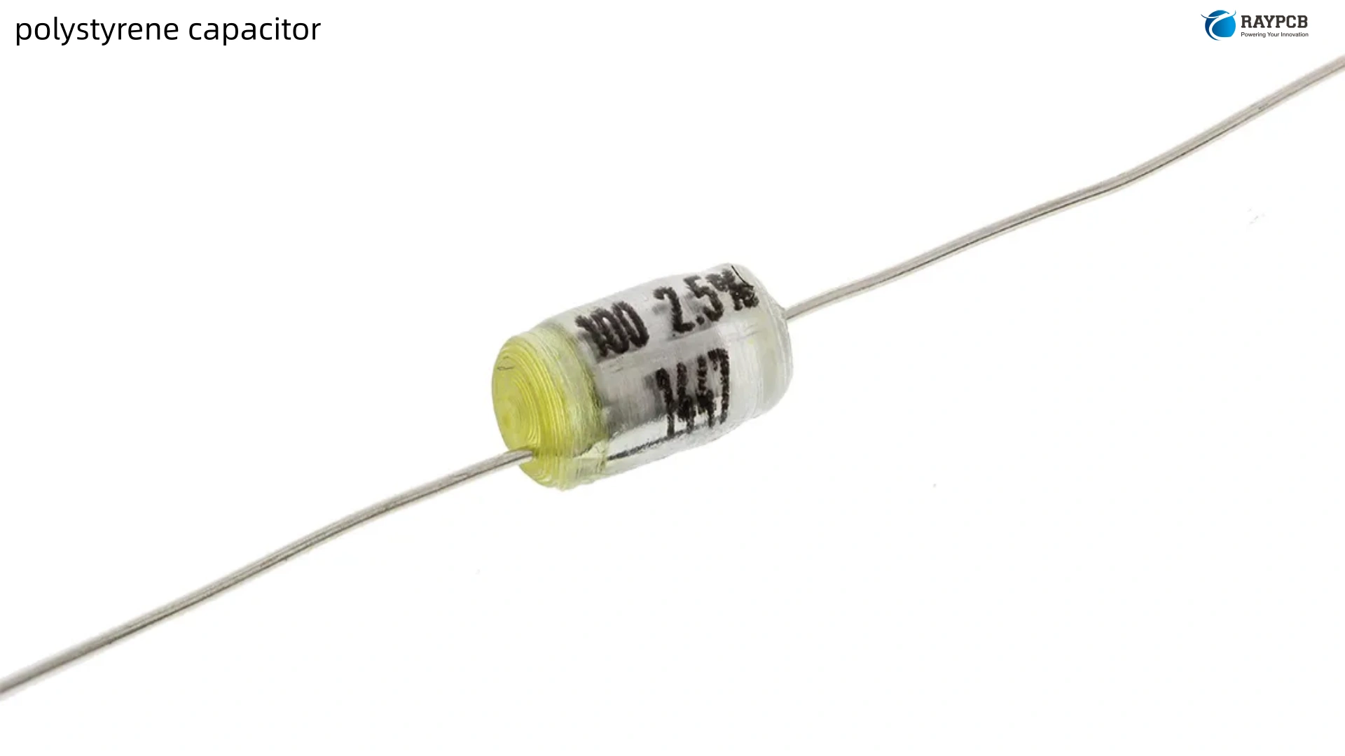
A polystyrene capacitor is a film and foil capacitor that uses polystyrene (PS) film as its dielectric material. The construction is straightforward: two strips of aluminum foil electrodes are interleaved with two layers of polystyrene film, then wound into a cylindrical roll and encased in a plastic or lacquered tube. Sometimes referred to as “Styroflex” in European literature — a brand name from the former Siemens/WIMA era — these capacitors were introduced into production around 1949 and remained a preferred precision component for decades.
The wound cylindrical construction is worth noting from a circuit behavior standpoint: because the foil strips are rolled up like a coil, the polystyrene capacitor has a small but measurable self-inductance. This makes it unsuitable for high-frequency applications above a few megahertz, where the inductive reactance begins to dominate. Below that frequency limit, however, its electrical behavior is essentially ideal.
Key Specifications at a Glance
| Parameter | Polystyrene Capacitor |
| Dielectric material | Polystyrene (non-polar) |
| Capacitance range | 10 pF to ~47 nF |
| Typical tolerance | ±5% to ±10%; precision types ±1% to ±2% |
| Temperature coefficient | −125 to −150 ppm/°C (linear, negative) |
| Operating temperature range | −40°C to +85°C (max +70°C for value stability) |
| Rated voltage | 30 V to 630 V DC |
| Dissipation factor (DF) | < 0.01% at 1 kHz, 25°C |
| Dielectric absorption | ~0.02% |
| Insulation resistance | Very high (RC time constant > 100,000 s) |
| Frequency suitability | Up to ~1 MHz (wound coil structure limits HF) |
| Construction | Film and foil only (no metallized version possible) |
| Physical format | Through-hole only (axial or radial lead) |
| SMD availability | None — cannot survive reflow soldering temperatures |
Why the Polystyrene Capacitor Was So Highly Regarded
To understand why engineers still discuss polystyrene capacitors with something approaching reverence, you need to understand what makes a capacitor “good” for precision applications. It is not just about tight initial tolerance — it is about how the capacitor behaves after manufacture, under bias, across temperature, and over time.
Dielectric Absorption: The Hidden Accuracy Killer
Dielectric absorption (DA) is the phenomenon where a capacitor, after being discharged, partially “recharges” itself from residual charge trapped in the dielectric. Think of it as a sponge that stays slightly wet even after wringing. In a sample-and-hold circuit, DA causes the output voltage to creep upward after the hold switch opens — directly limiting the accuracy of the measurement. In a precision integrator, DA causes output errors proportional to the input signal history. In audio circuits, some engineers argue DA introduces a subtle smearing of transient response.
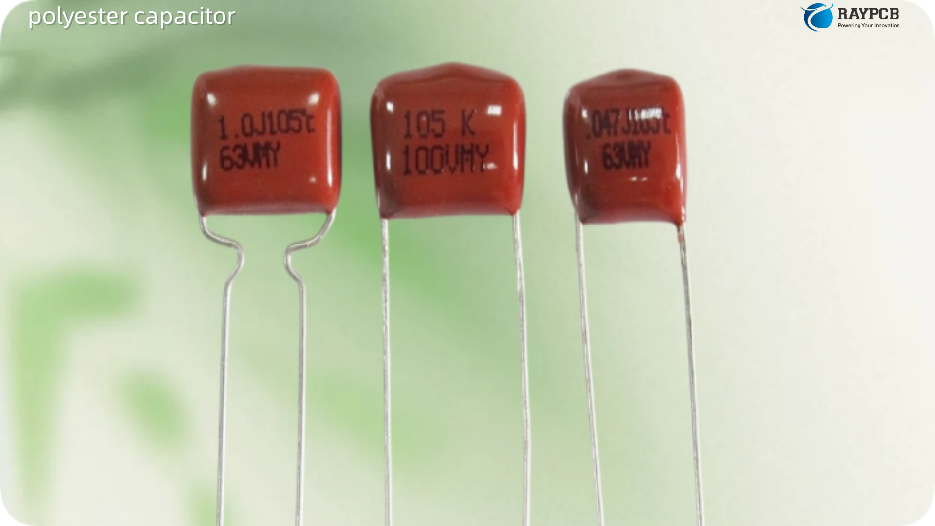
Polystyrene capacitors have a dielectric absorption of approximately 0.02% — one of the lowest figures of any practical dielectric, comparable only to Teflon (PTFE). Polyester (Mylar) capacitors by comparison show 0.2% to 0.5% DA, which is 10 to 25 times worse. For sample-and-hold circuits in precision ADC front ends and for precision integrators in instrumentation, the polystyrene capacitor’s DA performance was genuinely class-leading.
Temperature Stability: Predictable and Linear
The temperature coefficient of a polystyrene capacitor is typically −125 to −150 ppm/°C. This sounds significant, but the critical word is linear. Unlike Class 2 ceramic capacitors (X7R, X5R) whose capacitance changes non-linearly and unpredictably with temperature, polystyrene’s negative TC is consistent, repeatable, and predictable. Across the 0°C to +50°C range — the operating window of most commercial electronics — it delivers near-zero drift. The linearity also made polystyrene capacitors useful for deliberate temperature compensation in oscillator circuits, where their predictable −TC could offset the positive TC of other components.
Dissipation Factor: Nearly Lossless
The dissipation factor of a polystyrene capacitor is less than 0.01% at 1 kHz and room temperature. This means the polystyrene capacitor dissipates virtually no energy. In audio circuits, high dissipation factor is associated with audible coloration and loss of dynamics. In precision filters and timing circuits, high DF introduces phase errors and detuning. A dissipation factor below 0.01% means the capacitor is behaving as close to an ideal passive element as any practical component can achieve.
No Voltage Coefficient
Polystyrene capacitors show essentially no capacitance change with applied voltage. This is one of the chief advantages over Class 2 ceramic capacitors, which lose significant capacitance under DC bias — sometimes 50–80% of their rated value. In a precision filter or timing circuit, a capacitor that holds its value regardless of the signal voltage across it produces far more predictable and stable performance.
Long-Term Stability and Aging
Polystyrene capacitors do not undergo aging. The capacitance value measured the day they were manufactured is essentially the same decades later, provided they have never been overheated. Engineers servicing vintage test equipment from the 1960s and 1970s routinely find polystyrene capacitors still measuring within their original tolerance specification — a longevity record that is genuinely remarkable for an analog passive component.
Why Polystyrene Capacitors Became Obsolete
The story of the polystyrene capacitor’s disappearance is partly technical and partly industrial. The glass transition temperature of polystyrene is around 95°C, and the practical maximum operating temperature is +85°C, with permanent, irreversible value change occurring at around +70°C. This last point is critical: unlike most capacitors that recover after a brief thermal excursion, a polystyrene capacitor that sees excessive heat is permanently damaged. Its value simply shifts, and it does not return to the original specification on cooling.
This thermal sensitivity had two consequences. First, the polystyrene film could never be made in a metallized construction — the process of vacuum-depositing metal onto the film requires temperatures the polystyrene cannot tolerate. Metallized film construction is what allowed other film capacitors to be made much smaller at the same capacitance. Second, polystyrene capacitors were incompatible with wave soldering and completely incompatible with reflow soldering. In the era when through-hole assembly was standard, this was manageable. As PCB manufacturing transitioned to automated SMT and reflow, polystyrene’s inability to survive the process made it a dead end for new product design.
The supply chain collapse was equally decisive. The demise of polystyrene capacitors began around 1990 when the suppliers of capacitor-grade polystyrene film decided the volume was not worth the manufacturing effort. Their primary business was making Styrofoam products, and the thin precision film required for capacitors was a small, difficult-to-justify part of their output. Capacitor manufacturers placed large one-time bulk orders to stock the film, but once those reserves were depleted, production effectively ended. By approximately 2012, polystyrene film capacitors were largely gone from the market as active production items, with remaining stock continuing to trickle out of distributor warehouses.
Where Polystyrene Capacitors Were — and Still Are — Used
Despite the supply situation, it is worth knowing precisely where polystyrene capacitors were deployed, because it tells you where to look when servicing legacy equipment and informs the selection criteria for replacement parts.
Precision Application Areas
| Application | Why Polystyrene Was the Right Choice |
| Sample-and-hold circuits (ADC front ends) | Minimal DA prevents voltage creep after hold command |
| Precision active filters (Sallen-Key, state-variable) | Stable capacitance, no voltage coefficient, low DF |
| Audio signal path coupling and equalization | No distortion, no piezoelectric effect, no DA-induced smearing |
| Tuned IF filter networks | Predictable linear TC allows deliberate temperature compensation |
| Precision RC timing circuits | Stable value over temperature, no aging, predictable TC |
| Voltage-controlled filters (VCF) and oscillators (VCO) | Capacitance independent of applied voltage, essential for linearity |
| Precision integrators | Near-zero DA is essential for accurate integration |
| High-end audio preamplifiers and equalization stages | Low distortion, highly regarded by audiophile designers |
| Legacy test and measurement instruments | Long-term value stability keeps calibration valid for decades |
The Heat Damage Problem: A Critical Handling Warning
This deserves emphasis for anyone working with existing polystyrene capacitors or sourcing NOS (new old stock) parts. A polystyrene capacitor exposed to temperatures above approximately 70°C will undergo a permanent, irreversible shift in capacitance value. It does not recover on cooling. This means:
During manual soldering: Use a heat sink clip on the component lead between the capacitor body and the solder joint. Keep the iron time at the pad as brief as possible. This is not optional for precision applications.
In circuit: Keep polystyrene capacitors physically distant from heat-generating components — power resistors, regulators, transistors. If the ambient PCB temperature in the intended mounting location exceeds 70°C, polystyrene is the wrong component regardless of its electrical advantages.
For NOS stock: Verify values with a precision LCR meter before using stored polystyrene capacitors. Stock that has been exposed to heat or poor storage conditions may have shifted value permanently.
Modern Replacements for Polystyrene Capacitors
When the polystyrene capacitor cannot be sourced — which is the situation for any new design today — the question becomes which modern alternatives come closest to matching the characteristics that made polystyrene valuable.
Film Capacitor Dielectric Comparison for Precision Applications
| Dielectric | DA | DF @ 1kHz | Temp Coefficient | Max Temp | SMD Available | Voltage Coeff |
| Polystyrene (PS) | 0.02% | < 0.01% | −125 to −150 ppm/°C | +85°C | No | None |
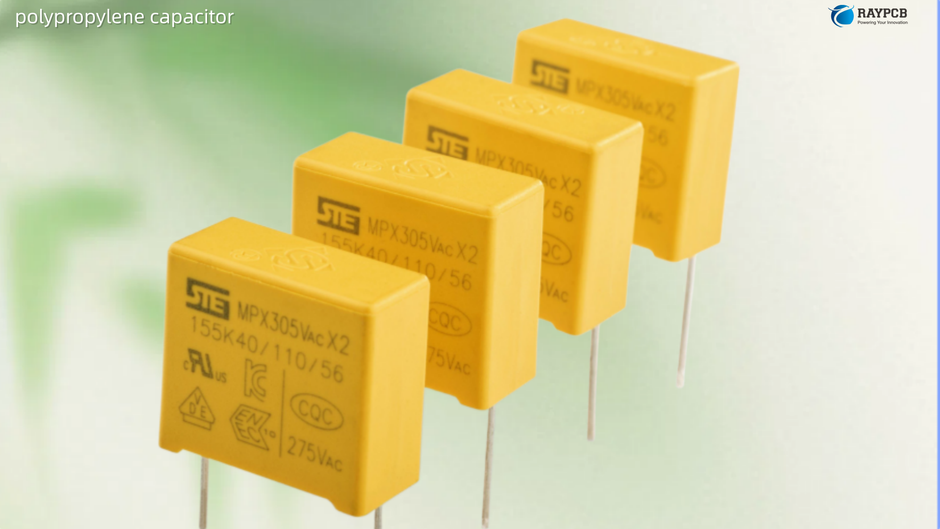
| Polypropylene (PP) | 0.02% | < 0.05% | −150 to −250 ppm/°C | +105°C | Limited | None |
| PTFE (Teflon) | ~0.02% | < 0.02% | −200 ppm/°C | +200°C | No | None |
| Polyphenylene Sulfide (PPS) | ~0.05% | < 0.05% | ~−120 ppm/°C | +125°C | Yes | Very low |
| Polycarbonate (PC) | ~0.08% | ~0.05% | ~0 ppm/°C | +125°C | No | Very low |
| Polyester (PET/Mylar) | 0.2–0.5% | 0.3–1% | Non-linear | +125°C | Yes | Low |
| C0G / NP0 Ceramic | < 0.06% | < 0.01% | 0 ±30 ppm/°C | +125°C | Yes | None |
Polypropylene film capacitors are the most commonly recommended replacement for polystyrene in precision and audio applications. The dielectric absorption is essentially identical at 0.02%, the dissipation factor is nearly as good, and the maximum operating temperature is higher at +105°C. The key difference is a temperature coefficient of −150 to −250 ppm/°C — more negative than polystyrene, and not zero. This means polypropylene is more temperature-sensitive across a wide range, though for many applications within a narrow temperature window it performs similarly. Polypropylene cannot be made in exactly the same physical sizes as polystyrene, and for SMD designs only very limited options exist.
C0G / NP0 ceramic capacitors deserve serious consideration as a polystyrene replacement in precision digital and instrumentation circuits, particularly for values below 1 nF. C0G ceramics have near-zero temperature coefficient (±30 ppm/°C), no voltage coefficient, no aging, and are available in SMD packages with excellent tolerances. Dielectric absorption is slightly higher than polystyrene but still very low at around 0.06%. For engineers comfortable with selecting and placing capacitors in PCB layouts, C0G ceramics in 0402 to 0805 packages are often the practical choice in modern designs where polystyrene values would have appeared in legacy schematics.
Polyphenylene sulfide (PPS) capacitors are an interesting middle ground — available in SMD construction (unlike polypropylene film), with good temperature stability and better dissipation factor than polyester. For precision filter and timing applications that need SMD packaging and better stability than a standard ceramic, PPS is worth evaluating.
PTFE (Teflon) capacitors match polystyrene’s electrical performance and exceed it in temperature range, but are expensive, difficult to source in common values, and not available in SMD construction. They remain the choice for aerospace and military precision circuits where cost is secondary to performance.
Identifying Polystyrene Capacitors in Vintage Equipment
When servicing gear that may contain polystyrene capacitors, knowing what to look for matters. They typically appear as small cylindrical components, usually with a clear, pale yellow or pale blue outer body — the rolled film construction is sometimes visible as a slightly transparent or translucent case. In European equipment, the Siemens/WIMA “KS” designation was common; in the U.S., manufacturers including Mallory, Cornell Dubilier, and Centralab produced variants. The capacitors are through-hole only, in either axial or radial lead configuration, and the axial style was far more common.
Values are typically in the range of 10 pF to 47 nF, marking them as the small-signal precision parts in a design rather than the bulk or bypass capacitors. If you find a small, unusually precise-looking leaded film capacitor in the feedback network of an op-amp, in a filter stage, or in the input path of a precision ADC, there is a reasonable chance it is polystyrene.
Useful Resources for Polystyrene Capacitors and Their Replacements
| Resource | What It Provides | Link |
| Electrocube White Paper: Polystyrene Alternatives | Detailed discussion of supply collapse and modern substitute options | electrocube.com |
| Electronics Notes: Polystyrene Capacitors | Technical overview of properties and applications | electronics-notes.com |
| RF Cafe: Capacitor Dielectric Comparison Table | Side-by-side comparison of all film and ceramic dielectric types | rfcafe.com |
| Doeeet: PS and PPS Film Capacitors | Detailed engineering specifications for PS and PPS dielectrics | doeeet.com |
| WIMA Film Capacitors | One of few remaining suppliers with NOS polystyrene stock; also produces polypropylene replacements | wima.com |
| Vishay Film Capacitors | Polypropylene and PPS film capacitors as modern precision alternatives | vishay.com/capacitors/film |
| DigiKey Film Capacitor Search | Filter by dielectric (polypropylene, PPS, PTFE) for sourcing replacement types | digikey.com |
| KEMET Film Capacitor Series | PHE and R series polypropylene; good reference specs for precision replacement selection | kemet.com |
Frequently Asked Questions About Polystyrene Capacitors
1. Can I still buy polystyrene capacitors today?
You can find NOS (new old stock) polystyrene capacitors from specialist suppliers, vintage component stockists, and some audiophile component retailers. WIMA and a few other European manufacturers still have quantities of polystyrene film stocked from historical bulk orders. The supply is finite and depleting — values in common precision ranges (100 pF to 4.7 nF) may still be found, but you cannot design a new product around the assumption of ongoing supply. For legacy repairs, check specialist suppliers like Michael Percy Audio, Hificollective, or Tedss.com for remaining stock.
2. What is the best replacement for a polystyrene capacitor in a vintage audio repair?
For audio signal path applications at values below 10 nF, polypropylene film capacitors (WIMA MKP or MKS2 series, Vishay MKP series, Panasonic ECQ series) are the closest direct replacement in terms of electrical performance. The DA and distortion characteristics are essentially identical to polystyrene. The temperature coefficient is slightly more negative (−150 to −250 ppm/°C versus −125 ppm/°C for polystyrene), but for audio applications operating in a narrow ambient temperature range, this difference is not audible or measurable in practice. For values below 1 nF where a surface-mount option is needed, a quality C0G ceramic from a reputable manufacturer (Murata, TDK, KEMET) is an excellent modern alternative.
3. Why can polystyrene capacitors not be made in SMD form?
Because polystyrene melts and permanently deforms at temperatures around 95°C, well below the peak temperatures of both wave soldering and reflow soldering (typically 245–260°C peak for SAC305 solder). The dielectric would be destroyed during the assembly process. Additionally, attempts to create a metallized polystyrene film — which would allow smaller physical sizes — failed for the same reason: the metallization process damages the film thermally. The wound coil construction of the standard polystyrene film capacitor also does not translate easily to the flat chip format of SMD components.
4. What happens to a polystyrene capacitor if it gets too hot?
The damage is permanent and silent. If the capacitor body reaches temperatures above approximately 70–75°C during use or soldering, the polystyrene film physically deforms slightly, causing a permanent change in the effective plate area and separation. The capacitance shifts, and it does not recover when the component cools. This is unlike most other capacitor failures which are abrupt or detectable by inspection. A thermally damaged polystyrene capacitor may appear completely normal visually and may even continue to function, just with a shifted value that throws off precision circuits in ways that are difficult to trace. If you suspect heat damage, measure with a precision LCR meter.
5. Is a polypropylene capacitor electrically equivalent to polystyrene?
Very nearly, but not identically. The dielectric absorption and low-distortion behavior are essentially the same at approximately 0.02%. The dissipation factor of polypropylene is slightly higher at 0.02–0.05% versus polystyrene’s < 0.01%, but both are far superior to polyester. The main practical difference is the temperature coefficient: polypropylene’s −150 to −250 ppm/°C is more negative and slightly less linear than polystyrene’s, which matters in circuits designed to exploit polystyrene’s near-zero TC over a specific temperature range, particularly oscillator compensating networks. For most audio and general precision applications, polypropylene is the correct and recommended substitute. The higher maximum temperature of polypropylene (+105°C) is also a genuine advantage — you do not need to worry about accidental heat damage during assembly the way you do with polystyrene.
Summary
The polystyrene capacitor occupies a unique position in the history of electronics: a component that reached near-ideal electrical performance in its specific area of application, only to be killed by a supply chain problem rather than superseded by anything clearly superior. Its dielectric absorption of 0.02%, dissipation factor below 0.01%, near-zero voltage coefficient, and decades of proven stability made it the preferred choice for precision timing, audio signal paths, sample-and-hold circuits, and precision filters across a 40-year production run.
For new designs, it is no longer an option. Polypropylene film capacitors are the functional replacement for most analog precision applications, with C0G ceramics covering the small-value SMD territory. For servicing legacy equipment, treating polystyrene capacitors with appropriate care — avoiding heat above 70°C, verifying value with a precision meter, and knowing where to source remaining stock — remains essential knowledge for any engineer working with precision analog hardware from the 1960s through the early 2000s.