X7R capacitorX7R Capacitor Explained: Properties, Applications & LimitationsX7R capacitor

X7R capacitor explained: decode the EIA code, understand DC bias derating, aging effects, and temperature characteristics โ€” with tables, tips, and design guidance.

If you’ve spent any time designing PCBs, you’ve probably typed “X7R” into a component search more times than you can count. It’s one of the most common ceramic capacitor dielectrics on the market โ€” and for good reason. But if you’re just starting out, or you’ve never stopped to think about what those three characters actually mean, this guide breaks it all down from a practical engineering standpoint.

What Is an X7R Capacitor?

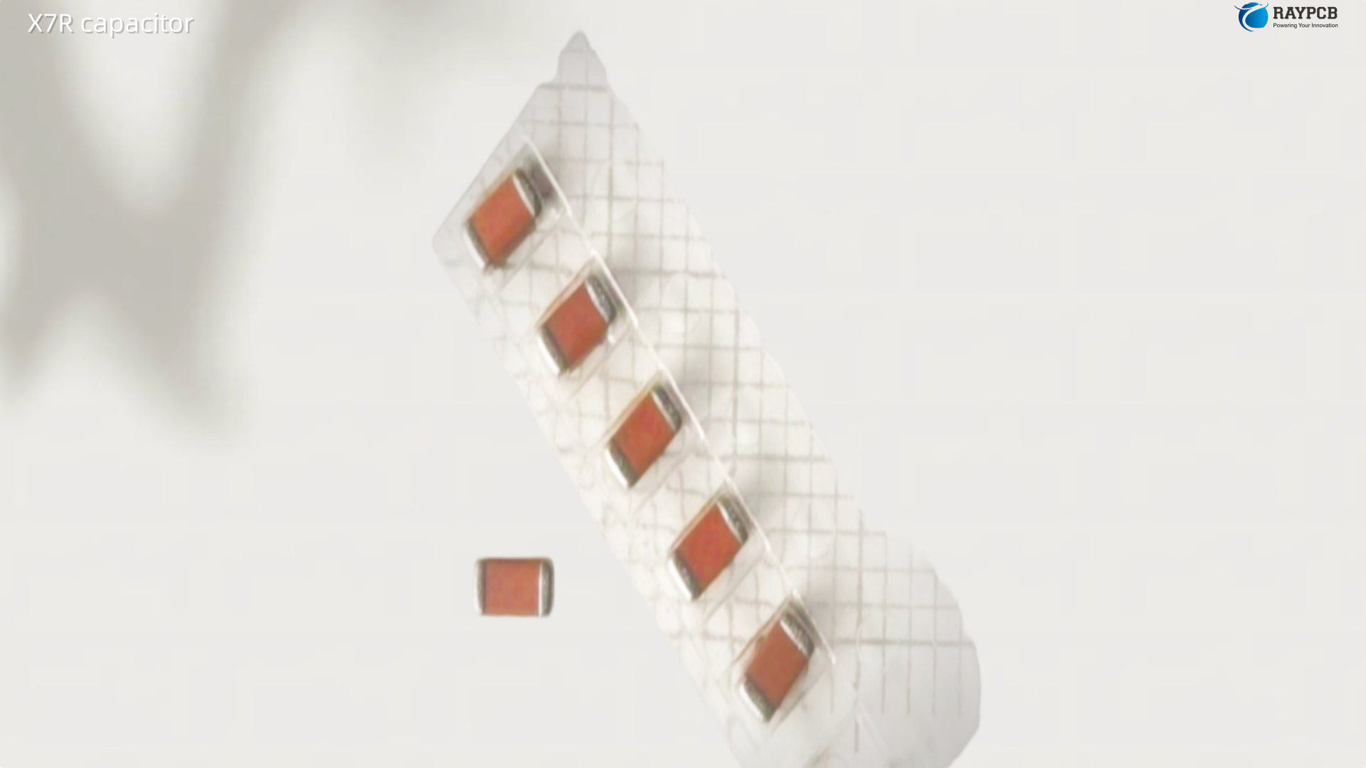
An X7R capacitor is a type of multilayer ceramic capacitor (MLCC) that uses a Class II ferroelectric ceramic dielectric material. The name “X7R” isn’t a brand or a random code โ€” it’s an EIA (Electronic Industries Alliance) standard designation that describes the temperature coefficient of capacitance (TCC).

Here’s how to decode the naming:

CharacterMeaningValue
XLower operating temperatureโˆ’55ยฐC
7Upper operating temperature+125ยฐC
RCapacitance change over temperatureยฑ15% max

So an X7R capacitor guarantees that its capacitance will stay within ยฑ15% of its rated value across the full temperature range of โˆ’55ยฐC to +125ยฐC. That’s a reasonably tight window for a ceramic cap, which is why it’s a workhorse in general-purpose electronics design.

X7R vs Other Ceramic Capacitor Dielectrics

Before diving deeper into X7R properties, it helps to see how it stacks up against the other common EIA code types you’ll encounter:

DielectricTemp RangeCapacitance ToleranceTypical Use
C0G (NP0)โˆ’55ยฐC to +125ยฐCยฑ30 ppm/ยฐCPrecision filters, resonators, RF circuits
X5Rโˆ’55ยฐC to +85ยฐCยฑ15%Consumer electronics, low-cost decoupling
X7Rโˆ’55ยฐC to +125ยฐCยฑ15%General-purpose bypass, coupling, filtering
X7Sโˆ’55ยฐC to +125ยฐCยฑ22%Higher capacitance density, moderate stability
Y5Vโˆ’30ยฐC to +85ยฐC+22% / โˆ’82%Bulk filtering, non-critical applications
Z5U+10ยฐC to +85ยฐC+22% / โˆ’56%Low-cost filtering where tolerance isn’t critical

C0G is the precision choice โ€” ultra-stable but hard to get in large capacitance values. Y5V gives you the most capacitance per dollar but falls apart under temperature, DC bias, and aging. X7R sits right in the sweet spot for the vast majority of digital and analog design work.

Key Electrical Properties of X7R Capacitors

Capacitance Range

X7R capacitors are available from as small as a few picofarads all the way up to around 100 ยตF in larger case sizes. The most common range in everyday design work is 1 nF to 10 ยตF, covering decoupling, filtering, and coupling applications in most mixed-signal and digital boards.

Voltage Ratings

X7R capacitors are available across a wide range of voltage ratings โ€” typically from 6.3 V up to 3 kV or higher depending on the manufacturer and case size. One critical thing to understand here: rated voltage is not working voltage. Thanks to DC bias effect (more on this below), you should derate X7R capacitors significantly in practice.

A general rule of thumb: work at no more than 50% of the rated voltage for stable capacitance, especially in critical decoupling or timing applications.

Temperature Coefficient and Stability

X7R is a ferroelectric material, which means its behavior is fundamentally different from the linear dielectric in a C0G cap. The ยฑ15% TCC is a maximum limit, not a flat curve โ€” actual capacitance variation depends on temperature, voltage, and even mechanical stress.

ESR and ESL

Ceramic capacitors in general have very low ESR (equivalent series resistance) and ESL (equivalent series inductance) compared to electrolytic and tantalum caps. X7R parts in small packages like 0402 or 0603 are excellent for high-frequency decoupling precisely because of this.

Typical ESR for X7R in a 0402 package is in the range of 5โ€“50 mฮฉ at 1 MHz, depending on capacitance value. ESL is generally under 1 nH.

The X7R Capacitor Aging Effect โ€” What Most Engineers Overlook

Here’s something that trips up newer designers: X7R capacitors lose capacitance over time. This is called dielectric aging, and it’s a natural property of ferroelectric ceramics.

Capacitance decreases logarithmically from the time the part is fired during manufacturing. A typical X7R part might lose 1โ€“3% of its capacitance per decade of hours (a “decade” here means going from 1 hour to 10 hours, 10 to 100 hours, and so on).

In practice, this means:

  • A brand-new X7R cap straight from the reel may already be aged somewhat
  • Soldering (applying heat) partially resets the aging clock โ€” capacitance goes back up, then starts declining again
  • After a year of operation, you may have a few percent less capacitance than the initial datasheet value

For most decoupling applications this is irrelevant. But in precision timing circuits or analog filters where tight capacitance tolerance matters, this is worth accounting for โ€” or worth switching to C0G instead.

DC Bias Effect: The Hidden Capacitance Killer

The DC bias effect is probably the most practically significant characteristic of X7R capacitors that engineers underestimate. When you apply DC voltage across an X7R cap, its effective capacitance drops โ€” sometimes dramatically.

Applied Voltage (% of Rated)Approximate Capacitance Remaining
10%~95โ€“100%
25%~80โ€“90%
50%~60โ€“75%
75%~40โ€“60%
100%~20โ€“50%

These numbers vary significantly between manufacturers, capacitance values, and case sizes. The key takeaway: always simulate or calculate with the derated capacitance, not the nominal value. A 10 ยตF / 10 V X7R cap running at 5 V might be delivering only 5โ€“7 ยตF of effective capacitance.

Modern component databases and simulation tools (like TI’s PSPICE models or Murata’s SimSurfing) let you check DC bias derating curves before committing to a part.

Mechanical Stress and Piezoelectric Effects

X7R uses a ferroelectric ceramic, which means it exhibits piezoelectric behavior. Mechanical stress โ€” from PCB flexing, mounting forces, or thermal expansion โ€” can generate small voltages across the capacitor. More practically, acoustic noise (“singing capacitors”) can occur when X7R parts are used in power conversion circuits at audible frequencies. If you’ve ever heard a faint high-pitched whine from a switching power supply, there’s a good chance it’s an X7R capacitor vibrating.

Mitigations include:

  • Using soft-termination capacitors designed to absorb mechanical stress
  • Orienting capacitors perpendicular to the PCB bending axis
  • Switching to C0G for noise-sensitive analog circuits
  • Using polymer capacitors where acoustic noise is unacceptable

Common Applications of X7R Capacitors

X7R is the default choice for a wide range of applications. Here’s where it makes sense:

Bypass and Decoupling

This is the bread-and-butter use case. In digital designs, X7R caps โ€” typically 100 nF in 0402 or 0603 packages โ€” are placed at every power pin to suppress high-frequency noise. Their low ESR and ESL make them far more effective than equivalent electrolytic caps for HF decoupling.

Coupling Capacitors

In AC coupling applications between amplifier stages, X7R offers adequate stability without the cost premium of C0G. Just be aware of DC bias if any DC offset is present on the signal line.

RC Filters

For low-precision filters where tight frequency tolerance isn’t critical, X7R is cost-effective. If you’re designing a simple anti-aliasing filter or a bypass RC network on a supply rail, X7R will work well. For precision filters, upgrade to C0G.

Timing Circuits (With Caveats)

X7R can work in timing circuits like oscillators and RC delays, but only if you account for aging, temperature drift, and DC bias effects in your tolerance stack-up. For tight timing accuracy, C0G is the better call.

Power Supply Filtering

Input and output filtering on switching power supplies commonly use X7R caps. Pay close attention to voltage derating here โ€” using a 10 V rated X7R at 9 V will give you a fraction of the stated capacitance. Use 25 V or 50 V rated parts on a 5 V rail instead.

Automotive and Industrial Electronics

The extended temperature range of โˆ’55ยฐC to +125ยฐC makes X7R suitable for automotive grade applications. Many X7R parts are available in AEC-Q200 qualified versions for safety-critical automotive use.

X7R Capacitor Limitations Summary

LimitationImpactMitigation
DC bias deratingCapacitance drops significantly under voltageDerate to 50% Vrated; use larger rated parts
Temperature variation ยฑ15%Affects filter cutoff and timingVerify at temperature extremes; switch to C0G for precision
AgingGradual capacitance loss over timeOver-spec capacitance by 10โ€“20%; use C0G for precision timing
Piezoelectric noiseAcoustic buzz in switching circuitsSoft-termination parts; orient perpendicular to flex
Not suitable for precision analogToo much variation for precision circuitsUse C0G/NP0 for precision analog

How to Choose the Right X7R Capacitor

When you’re selecting an X7R cap in a design, work through this checklist:

Step 1: Define the required capacitance under real operating conditions. Work backwards from effective capacitance after DC bias derating and temperature variation.

Step 2: Choose the voltage rating with margin. A 2:1 derating (never exceed 50% of rated voltage) is a common industry standard. For critical power supply decoupling, 4:1 gives more headroom.

Step 3: Select case size for frequency performance. Smaller packages have lower parasitic ESL, which improves high-frequency decoupling. 0402 and 0201 are preferred for GHz-range designs.

Step 4: Check for AEC-Q200 if designing for automotive or high-reliability use.

Step 5: Verify availability and manufacturer stock. MLCC supply chains can be volatile. Always qualify at least two sources.

Useful Resources for X7R Capacitor Selection

These tools and databases are genuinely useful in day-to-day design work:

ResourceWhat It’s Good ForLink
Murata SimSurfingSimulate DC bias, temperature, and frequency characteristicsproduct.murata.com
TDK Product SelectorParametric MLCC search with derating curvesproduct.tdk.com
Kemet KSIMSPICE model generation and capacitor simulationksim3.kemet.com
Vishay WCAP SelectorParametric search with S-parameter datavishay.com
Digi-Key Parametric SearchCross-vendor MLCC search with real-time pricingdigikey.com
Mouser ElectronicsBroad MLCC catalog with datasheet accessmouser.com
EIA RS-198 StandardOfficial temperature coefficient code definitionsAvailable from ANSI/IEC standards bodies

Frequently Asked Questions About X7R Capacitors

What does X7R mean on a capacitor?

X7R is an EIA standard temperature characteristic code for ceramic capacitors. “X” means the lower temperature limit is โˆ’55ยฐC, “7” means the upper limit is +125ยฐC, and “R” means capacitance can change up to ยฑ15% across that range. It’s one of the most popular Class II ceramic dielectric codes in use.

Is X7R better than C0G?

It depends on the application. C0G is more stable โ€” it has near-zero temperature drift and no DC bias effect. But it’s harder to get in large capacitance values and costs more. X7R gives you higher capacitance in smaller packages at lower cost, making it the right choice for decoupling, general filtering, and coupling where precision isn’t critical. C0G wins for precision timing, resonator circuits, and high-accuracy analog filtering.

What’s the difference between X7R and X5R?

The only difference is the upper temperature limit: X7R goes up to +125ยฐC, while X5R tops out at +85ยฐC. Both have ยฑ15% capacitance variation. X5R is fine for consumer electronics that will never get hot. X7R is the right choice if your design needs to work in automotive, industrial, or high-power environments where temperatures can exceed 85ยฐC.

Why does my X7R capacitor measure a lower value than rated?

Most likely because of DC bias effect or aging. If you’re measuring with a DC voltage applied, capacitance can drop significantly โ€” sometimes by 50% or more at rated voltage. Even at rest, capacitors age from the time they’re manufactured. For accurate measurement, measure at low AC voltage with no DC bias, and make sure the part hasn’t been sitting on a shelf for years.

Can I use X7R capacitors in RF circuits?

For low-frequency RF applications (below a few hundred MHz), X7R works fine. For high-frequency RF, microwave, or any circuit where Q factor and precise resonance matter, use C0G. The dielectric losses and parasitic instabilities of X7R ferroelectric material degrade RF performance significantly compared to C0G.

Final Thoughts

The X7R capacitor is a reliable, cost-effective workhorse that belongs in most PCB designs โ€” but it comes with real constraints that can bite you if you ignore them. DC bias derating is the most common gotcha, especially in power supply filtering. Aging matters if you’re designing something with a 10+ year service life. And if you hear your board singing at you, check those X7R caps on your switcher output.

For most general-purpose bypass, coupling, and filtering work, X7R is the right call. Know its limits, derate appropriately, and it’ll serve you well across the full operating life of your product.

X and Y Safety Capacitors: EMI Suppression & Mains Safety Explained

X2 capacitor and Y safety capacitor guide for engineers: classifications, EMI suppression, leakage limits, PCB layout rules, certification requirements, and selection tables.

Every switching power supply, motor drive, and mains-connected appliance you’ve ever designed or worked on has at least one safety capacitor somewhere in its EMI filter. Most engineers know they need an X2 capacitor across the line and Y capacitors to ground โ€” but fewer understand exactly why the classification system exists, what happens when these parts fail, and why substituting an unmarked film capacitor “that’s the same value” is a potentially lethal mistake.

This guide covers the complete picture: the regulatory framework behind X and Y safety capacitor classifications, how they suppress differential and common-mode EMI, how to select and apply them correctly, and the real-world failure modes that the classification system is designed to prevent.

Why Safety Capacitors Exist: The Regulatory and Safety Background

When you connect a capacitor directly across mains voltage โ€” or between mains and a grounded chassis โ€” you’re creating a potential shock or fire hazard if that capacitor fails. Conventional film capacitors fail short-circuit when overstressed. A shorted capacitor across 230V AC is a fire hazard. A shorted capacitor between live and a grounded enclosure puts mains voltage on the chassis โ€” a lethal shock hazard.

Safety capacitors are designed and tested to fail in a predictable, safe way: open-circuit. The dielectric and metallization system are engineered so that when breakdown occurs, the fault energy vaporizes the metallization around the failure point, isolating it rather than creating a sustained arc. This self-healing behavior is the core safety property, and it’s what the X and Y classification system certifies.

The International Standards Behind X and Y Capacitors

The primary governing standard is IEC 60384-14, which defines the classification, performance requirements, and test methods for fixed capacitors used in equipment connected to AC mains. North American markets reference UL 60384-14 (harmonized with IEC) and the older UL 1414 for specific applications.

Equipment-level EMC standards โ€” CISPR 22/EN 55022 for IT equipment, EN 55032 for multimedia equipment โ€” define the conducted emissions limits that X and Y capacitors help meet. These limits appear in certification requirements for CE marking in Europe, FCC Part 15 in the United States, and equivalent marks in other markets.

The practical reality for a PCB designer is that you need safety capacitors that carry the correct safety mark from an approved certification body โ€” VDE, UL, CSA, ENEC, CQC โ€” depending on your target markets. An unmarked capacitor of the same value and voltage rating does not satisfy this requirement, regardless of its actual electrical properties.

Understanding the X and Y Classification System

X Capacitors: Line-to-Line EMI Suppression

X capacitors are connected directly across the AC mains โ€” between Line (L) and Neutral (N). They suppress differential-mode interference, which is noise that appears between the two mains conductors. In a switching power supply, the switching transients of the main power transistor couple back onto the mains as differential-mode EMI, and the X capacitor provides a low-impedance path for these high-frequency currents to circulate locally rather than propagating back onto the mains network.

X capacitors are classified by their rated voltage and the impulse voltage they must survive:

ClassApplicationRated Voltage (VAC)Impulse Voltage (Vpeak)Typical Failure Mode Requirement
X1High impulse environments>250V to 440V4,000VOpen circuit
X2General mains applicationsโ‰ค250V2,500VOpen circuit
X3Less critical applicationsโ‰ค250VNot specifiedOpen circuit

X2 capacitors are the most common class used in power supply EMI filters for 230V and 120V mains applications. The 2,500V impulse rating covers the transients that occur in normal mains environments โ€” switching of large loads on the same circuit, indirect lightning coupling, and utility switching events.

X1 capacitors are required in industrial environments where more severe impulse conditions are expected โ€” 400/440V three-phase systems, industrial machinery with large motor loads, and applications near high-energy switching equipment.

X3 capacitors are rarely used in modern designs because they have no impulse voltage requirement, which makes them inappropriate for any mains-connected application where transient overvoltages are possible.

Y Capacitors: Line-to-Ground EMI Suppression

Y capacitors connect between a mains conductor (Line or Neutral) and the protective earth ground. They suppress common-mode interference โ€” noise that appears identically on both mains conductors relative to ground. Common-mode EMI is typically generated by high-frequency switching currents that flow through parasitic capacitances between the switching node and the chassis or heatsink.

Because Y capacitors bridge the isolation barrier between mains potential and accessible ground, their failure mode is critical: a shorted Y capacitor puts mains voltage on the chassis, creating a shock hazard. The classification system for Y capacitors reflects the level of isolation required:

ClassApplicationReinforced/Basic InsulationRated Voltage (VAC)Capacitance LimitImpulse Voltage
Y1Across reinforced or double insulationDouble insulation250VNo limit8,000V
Y2Across basic insulation, earthed equipmentBasic insulation150/250VNo limit5,000V
Y3Across basic insulationBasic insulation250VNo limitNot specified
Y4Across basic insulationBasic insulation150VNo limitNot specified

Y2 capacitors are the workhorse class for most consumer and industrial equipment connected to earthed mains supplies. They’re rated for basic insulation โ€” meaning the chassis is grounded and a single failure (the Y capacitor shorting) doesn’t create a shock hazard because the protective earth trips the breaker.

Y1 capacitors are required in Class I equipment with reinforced insulation and in medical equipment where leakage current is strictly controlled. The higher impulse rating (8,000V) and double insulation requirement reflect the more demanding safety environment.

Why Y Capacitor Values Are Limited by Leakage Current

Here’s something that surprises engineers encountering safety capacitor design for the first time: Y capacitor values are strictly limited by the leakage current they allow to flow through the protective earth.

A Y capacitor connected between Live and PE allows a continuous current to flow through the PE conductor equal to:

I_leakage = V_mains ร— 2ฯ€ ร— f ร— C_Y

For a 230V, 50Hz system with a 10 nF Y capacitor:

I_leakage = 230 ร— 2ฯ€ ร— 50 ร— 10ร—10โปโน = 0.72 mA

IEC 60950-1 (general IT equipment) limits touch current to 3.5 mA. IEC 60601-1 (medical equipment) limits patient leakage current to 100 ยตA for type B equipment and 10 ยตA for type CF (cardiac-floating). This is why you’ll see much smaller Y capacitor values โ€” or none at all โ€” in medical power supplies, and why the EMC performance of medical equipment is often compromised compared to industrial equipment.

The practical capacitance limit for Y2 capacitors in 230V/50Hz equipment targeting IEC 60950-1 compliance is approximately 47 nF per capacitor from Line to PE and Neutral to PE combined.

How X and Y Capacitors Suppress EMI: The Filter Topology

The Standard EMI Filter Structure

A complete mains EMI filter using safety capacitors has a defined topology that addresses both differential-mode and common-mode interference. Understanding the signal flow makes it much easier to size the components correctly.

The standard single-stage filter topology from mains inlet to SMPS consists of:

From mains inlet toward load: Y capacitor (L-PE) โ†’ Common-mode choke โ†’ Y capacitor (N-PE) on output side, with X capacitor (L-N) on both input and output of the common-mode choke.

Each element in this chain targets specific interference paths:

ComponentPositionMode SuppressedMechanism
X capacitor (input)L-N at mains inletDifferential-modeShunts L-N high-frequency current
Y capacitors (input)L-PE, N-PE at inletCommon-modeShunts CM current to PE
Common-mode chokeSeries in L and NCommon-modeHigh CM impedance, low DM impedance
X capacitor (output)L-N after CM chokeDifferential-modeLimits CM choke differential leakage
Y capacitors (output)L-PE, N-PE after chokeCommon-modeFinal CM attenuation stage

Differential Mode vs. Common Mode: What’s Actually Being Filtered

Differential-mode (DM) noise flows in opposite directions on Line and Neutral โ€” it’s the “normal” signal path for both the power current and for DM interference. The X capacitor presents a low impedance across L-N at high frequencies, shorting out DM interference before it reaches the mains.

Common-mode (CM) noise flows in the same direction on both Line and Neutral, returning through the PE conductor. It’s generated by parasitic capacitance between switching nodes and grounded heatsinks or chassis. The Y capacitors provide a controlled, low-impedance path for CM currents to return to the source through PE rather than coupling to the mains.

The common-mode choke โ€” two windings on a high-permeability toroidal core wound to cancel DM flux while presenting high impedance to CM currents โ€” is the key element that works with the Y capacitors to attenuate common-mode noise over the 150 kHz to 30 MHz frequency range covered by CISPR conducted emissions limits.

Selecting the Right X and Y Capacitors: Practical Engineering Guidance

Selecting X2 Capacitors for Power Supply EMI Filters

For most consumer and light industrial equipment operating from 85โ€“265V AC mains, the X2 class is the correct choice. Key selection parameters:

Capacitance value: X2 capacitors for differential-mode filtering typically range from 100 nF to 470 nF. Larger values provide more attenuation but increase the voltage surge energy that must be absorbed safely. Start with 220 nF for a first-pass design and adjust based on pre-compliance EMC testing results.

Voltage rating: For X2 class, 275V AC or 305V AC rated parts are standard for 230V mains. The AC voltage rating must exceed the nominal mains voltage โ€” the safety rating provides the impulse margin. Never use a capacitor with an AC voltage rating below the mains voltage.

Capacitance tolerance: ยฑ10% or ยฑ20% is standard for EMI filter capacitors. The filter attenuation is not sensitive to exact capacitance values, so tight tolerance is unnecessary and adds cost.

Lead pitch and package: X2 capacitors come in standard through-hole packages with 10mm, 15mm, 22.5mm, and 27.5mm lead pitches, as well as SMD packages for automated assembly. The creepage and clearance distances built into the package body are part of the safety certification โ€” don’t clip leads shorter than specified or use spacers that reduce PCB creepage.

Selecting Y2 Capacitors for Common-Mode Suppression

Capacitance value: Y2 capacitors for common-mode filtering are limited by leakage current requirements, typically 1 nF to 47 nF. For equipment with generous leakage current allowance (industrial, 3.5 mA limit), values up to 47 nF are practical. For equipment with strict leakage limits (medical, portable), 1 nF or less per Y capacitor may be the maximum.

Voltage rating: Y2 capacitors are typically rated at 250V AC or 300V AC. The impulse rating (5,000V for Y2) is the more demanding requirement, driving the choice of dielectric thickness and grade.

Placement: Y capacitors between Line/Neutral and PE should be placed as close to the mains inlet as physically possible to intercept conducted CM currents before they propagate into the equipment. A second Y capacitor pair on the secondary side of the common-mode choke improves high-frequency attenuation.

X and Y Capacitor Selection Summary Table

ParameterX1X2Y1Y2
Typical applicationIndustrial 400VConsumer 230V/120VMedical, double insulatedGeneral earthed equipment
AC voltage rating440V275/305V250V250/300V
Impulse voltage4,000V2,500V8,000V5,000V
Typical capacitance100โ€“470 nF100โ€“470 nF1โ€“10 nF1โ€“47 nF
Leakage concernNoNoYes (critical)Yes
Common dielectricMetallized PP filmMetallized PP filmCeramic (Class II) or filmCeramic (Class II) or film
Failure modeOpenOpenOpenOpen

PCB Layout Guidelines for Safety Capacitors

Creepage and Clearance Requirements

Safety capacitors bridge isolation barriers, which means the PCB traces connected to them must maintain required creepage and clearance distances. These are not arbitrary โ€” they’re mandated by IEC 60664-1 and the product safety standards that reference it.

For 230V mains-connected equipment in a Pollution Degree 2 environment (typical indoor equipment):

Insulation LevelMinimum ClearanceMinimum Creepage (CTI โ‰ฅ175, Material Group IIIa)
Basic insulation1.5 mm2.5 mm
Reinforced insulation3.0 mm5.0 mm
Double insulation3.0 mm5.0 mm

These distances apply to copper traces on the PCB as well as component lead spacing. Y capacitors crossing the primary-to-secondary barrier in an isolated power supply must maintain reinforced insulation distances โ€” the capacitor package itself is designed for this, but your PCB layout must not violate it with adjacent copper.

Common Layout Mistakes with Safety Capacitors

The most frequent PCB layout error with Y capacitors is routing the PE return trace through a long path before reaching the chassis ground point. Any inductance in the PE trace reduces the effectiveness of the Y capacitors at high frequencies. The PE connection should be as short and direct as possible โ€” ideally directly to the chassis mounting point rather than routed through the PCB ground plane.

For X capacitors, placing them close to the mains inlet connector prevents high-frequency currents from circulating through the PCB before being shunted. An X capacitor at the far end of a long PCB trace has significantly reduced effectiveness because the trace inductance prevents the capacitor from presenting a low impedance at the frequencies of interest.

Thermal Considerations

Safety capacitors in mains filters carry continuous reactive current. For a 470 nF X2 capacitor on 230V/50Hz, the reactive current is approximately 34 mA โ€” not enough to cause significant heating in the capacitor itself, but the PCB traces and through-hole pads must be sized for this current. In high-frequency operation above 50 Hz (variable frequency drives, aircraft 400 Hz mains), this current scales linearly with frequency and becomes more significant.

Regulatory Compliance and Certification Requirements

What Safety Marks Are Required?

For equipment sold in different markets, the safety capacitors in your design must carry the appropriate certification marks:

MarketRequired MarksCertification Body
European UnionVDE, ENEC, or equivalentVDE, TรœV, KEMA-KEUR
North AmericaUL, CSAUL, CSA Group
ChinaCQC (compulsory for many categories)CQC
JapanJIS mark or PSEJET, UL Japan
GlobalMultiple marks or IECEx-basedMultiple

The key requirement from a procurement standpoint: the safety mark must be on the component itself (physically marked on the capacitor body), not just in a test report. During product safety audits, inspectors verify the marks on installed components.

Working with Approved Component Databases

Rather than attempting to verify individual capacitor certifications manually, use the manufacturer’s certified part number lists and cross-reference with the certification body’s online databases:

Major approved X2 capacitor manufacturers for reference: KEMET, Vishay, WIMA, Panasonic, TDK/EPCOS, Murata, Wรผrth Elektronik, AVX. All publish approved part number lists linked to their certification marks.

Useful Resources for X and Y Safety Capacitor Design

These references are essential for any engineer working with mains-connected equipment:

  • IEC 60384-14 Standardย โ€” iec.ch/storeย โ€” the primary international standard defining X and Y capacitor classifications and test requirements
  • KEMET X2/Y2 Safety Capacitor Selectorย โ€” kemet.com/en/us/capacitors/film/safety-capacitorsย โ€” parametric search tool with certification filter by market
  • Wรผrth Elektronik WCAP-FTXX Series Application Notesย โ€” we-online.com/components/products/WCAP-FTXXย โ€” includes complete EMI filter design guidance with X and Y component sizing
  • TDK/EPCOS Safety Capacitor Portfolioย โ€” tdk-electronics.tdk.com/en/safety-capacitorsย โ€” full lineup of X1, X2, Y1, Y2 with cross-market certifications
  • VDE Component Certification Databaseย โ€” vde.com/en/institute/services/certification/component-certificationย โ€” searchable database of VDE-approved components including X and Y capacitors
  • UL Product iQ Databaseย โ€” iq.ul.comย โ€” official UL certified component database, search by manufacturer and part number
  • Murata EMI Filter Design Tool (SimSurfing)ย โ€” product.murata.com/simsurfingย โ€” simulation tool for EMI filter frequency response with safety capacitor models
  • CISPR 32 / EN 55032 Conducted Emissions Standardย โ€” iec.chย โ€” the emissions limits standard that X and Y capacitors help meet for multimedia equipment
  • Wรผrth Elektronik “EMC Design Guide” (free download)ย โ€” we-online.com/emc-design-guideย โ€” comprehensive practical guide covering safety capacitor selection and filter topology

Frequently Asked Questions About X and Y Safety Capacitors

Q1: Can I use an X2 capacitor in place of a Y2 capacitor to get a higher capacitance value?

Absolutely not, and this is one of the most dangerous substitutions in mains filter design. X2 capacitors are designed to fail open-circuit when connected line-to-line โ€” but they are not designed or tested for the isolation requirements between mains and earth that Y capacitors must meet. An X2 capacitor placed line-to-PE lacks the impulse voltage rating, the creepage distance, and the insulation structure required for Y applications. If it fails short-circuit (which is possible, since it wasn’t designed for this position), you put mains voltage on the chassis. Use Y-rated capacitors in Y positions, always.

Q2: My equipment needs very low leakage current โ€” how do I maintain EMC performance with tiny Y capacitor values?

This is the fundamental tension in medical and battery-operated equipment EMC design. The solutions available to you are: increase the common-mode choke impedance (use a larger core with more turns or higher permeability material) to compensate for reduced Y capacitance; add multiple filter stages with small Y capacitors in each stage; use a shielded transformer with a Faraday screen connected to both primary and secondary grounds to intercept CM currents without contributing leakage; or accept a higher conducted emission level and address the EMC budget at the system level through enclosure shielding.

Q3: What’s the difference between metallized film X2 capacitors and ceramic Y2 capacitors โ€” why the different dielectrics?

X2 capacitors use metallized polypropylene film because PP film has excellent self-healing properties at the capacitances and voltages required โ€” the metallization evaporates cleanly around breakdown sites without forming carbon tracking paths. Ceramic Y2 capacitors use a Class II (X7R or similar) or Class I ceramic because ceramic can be manufactured with very thin, uniform dielectric layers in small packages, and the material has good self-healing under impulse conditions. Some Y2 capacitors also use metallized film โ€” particularly in higher-capacitance values. The choice between ceramic and film Y capacitors often comes down to package size, temperature stability requirements (film is better), and cost.

Q4: How do I verify that safety capacitors in my design are properly certified without buying samples and sending them to a lab?

Use the certification body’s online databases directly. For UL certification, search UL Product iQ (iq.ul.com) by manufacturer and part number. For VDE, use the VDE component certification database. For ENEC, check the ENEC certification holders list at enec.eu. The manufacturer’s datasheet will list certification file numbers โ€” cross-reference these numbers in the official database to confirm the specific part number you’re buying is covered. This takes 10 minutes and is far faster than waiting for lab results.

Q5: What happens to X2 capacitors over time? Is there a replacement interval?

X2 capacitors degrade through two primary mechanisms: dielectric aging from continuous AC voltage stress, and cumulative damage from surge events. The self-healing process that makes them safe also gradually reduces the effective electrode area each time a micro-breakdown is healed โ€” capacitance decreases slowly over time. Modern X2 capacitors from reputable manufacturers have design lifetimes of 100,000 hours or more at rated conditions. In practice, well-designed power supplies outlast their X2 capacitors in harsh environments (high temperature, severe surge exposure), while in benign environments the capacitors can last the life of the equipment. There’s no standard replacement interval for consumer equipment, but industrial equipment in harsh environments benefits from periodic capacitance measurement to detect degraded parts.

Variable Capacitor: How It Works and Where It’s Used in Radio Circuits

Learn how variable capacitors work in radio circuits. Covers air variables, varactor diodes, trimmer types, VCO design, antenna tuning, and practical selection guidance.

Walk into any serious amateur radio shack or open up a vintage communications receiver, and one of the first things you’ll notice is the satisfying mechanical click of a tuning dial connected to an air-variable capacitor. That smooth, precise adjustment of capacitance is what allows a receiver to select one station out of dozens crowding the same frequency band. The variable capacitor is one of the most fundamental components in RF and radio circuit design, and understanding how it works, what types exist, and where each type belongs is knowledge that every RF engineer should have solid.

This guide covers everything from the physics of how a variable capacitor changes capacitance, through the major types and their electrical characteristics, to practical design guidance for tuning circuits, impedance matching, and voltage-controlled oscillators. Whether you’re designing a software-defined radio front end, restoring a vintage shortwave receiver, or building a VHF impedance matching network, this is the reference you want.

What Is a Variable Capacitor?

A variable capacitor is a capacitor whose capacitance can be intentionally adjusted โ€” either mechanically, electrically, or thermally โ€” over a defined range. Unlike fixed capacitors where the plate area, dielectric material, and plate separation are permanently established during manufacture, a variable capacitor provides a means to change one or more of these parameters during operation or setup.

The fundamental capacitance equation governs all variable capacitor operation:

C = ฮต ร— A / d

where ฮต is the permittivity of the dielectric (or air), A is the overlapping plate area, and d is the separation between plates. Variable capacitors exploit changes in A (rotating plate types), changes in d (compression trimmers, varactor diodes under reverse bias), or changes in ฮต (some specialty types) to achieve adjustable capacitance.

The range of applications spans from the manually tuned air-variable capacitors in HF receivers covering a 10:1 frequency range, down to tiny SMD trimmer capacitors used for one-time alignment of oscillator circuits during production, and varactor diodes with capacitance electronically controlled by a tuning voltage in phase-locked loop synthesizers.

How a Variable Capacitor Works: The Physics

Rotating Plate (Air Variable) Mechanism

The classic air-variable capacitor consists of two sets of semicircular aluminum plates โ€” a fixed stator set and a rotating rotor set โ€” interleaved with air as the dielectric. As the rotor shaft turns, the overlapping area between rotor and stator plates changes from zero (plates fully meshed at 90ยฐ out of phase โ€” minimum capacitance) to maximum (plates fully overlapping โ€” maximum capacitance).

The relationship between shaft angle and capacitance depends on the plate shape. Standard semicircular plates give a capacitance that varies roughly linearly with rotation angle. Specially shaped plates โ€” paddles with nonlinear profiles โ€” can produce logarithmic, straight-line frequency, or other custom capacitance-versus-angle curves that linearize the dial scale for specific applications.

Air as the dielectric gives ฮตr = 1.0006, essentially unity, which means the capacitance is determined almost entirely by plate geometry. This also means extremely low loss โ€” the Q of an air-variable capacitor is limited primarily by contact resistance in the rotor bearings and frame construction, routinely achieving Q values of 1,000 or more at HF frequencies.

Compression Trimmer Mechanism

Compression trimmer capacitors change capacitance by varying plate separation rather than overlap area. A stack of interleaved metal foil and dielectric sheets (typically mica, ceramic, or PTFE) is compressed or released by a screw adjustment. Tightening the screw reduces the average plate spacing d, increasing capacitance. These are one-time or infrequent adjustment devices used for production alignment rather than tuning during operation.

Varactor Diode: Voltage-Controlled Capacitance

The varactor diode (also called varicap) isn’t a mechanical device at all โ€” it exploits the voltage-dependent width of the depletion region at a reverse-biased p-n junction. A wider depletion region means a larger effective plate separation, lower capacitance. A narrower depletion region means higher capacitance.

The capacitance-voltage relationship for a varactor follows:

C(V) = Cโ‚€ / (1 + V/ฯ†)โฟ

where Cโ‚€ is the zero-bias capacitance, ฯ† is the built-in junction potential (โ‰ˆ0.7V for silicon), V is the reverse bias voltage (positive value), and n is the grading coefficient (0.3โ€“0.5 for abrupt junctions, up to 2 for hyperabrupt junctions designed for wide tuning range).

Hyperabrupt varactors achieve capacitance ratios of 10:1 or more across their voltage range โ€” enough to tune an LC oscillator over an octave from a single voltage control. This makes them the dominant technology in voltage-controlled oscillators (VCOs) for modern frequency synthesizers, phase-locked loops, and electrically tunable filters.

Types of Variable Capacitors: Classification and Comparison

Air Variable Capacitors

Air variables are the classic manually tuned capacitor for HF radio applications. They come in several frame constructions:

Single-gang: One rotor section, one stator section. Used where a single tuned circuit is adjusted โ€” transmitter output tuning, antenna matching units.

Multi-gang: Two, three, or four rotor-stator sections on a common shaft, used to simultaneously tune multiple resonant circuits that track together. Classic AM broadcast receiver designs use two or three-gang variables to tune the RF amplifier input, mixer input, and local oscillator simultaneously.

Differential variable: Two sections wired so that as one increases capacitance, the other decreases. Used in bridge circuits and phase-shifting networks where the ratio of two capacitances is the controlled variable.

Air Variable ParameterTypical RangeNotes
Capacitance range10โ€“500 pFCustom ranges available
Minimum capacitance5โ€“15 pFResidual stray capacitance
Voltage rating500โ€“3,000VHigher for transmitter types
Q factor at 1 MHz1,000โ€“5,000Limited by contact resistance
Temperature coefficientNear zeroAir dielectric is stable
Tuning resolutionContinuous analogLimited by mechanical backlash

Trimmer Capacitors (Preset Variables)

Trimmer capacitors are adjusted infrequently โ€” during manufacturing alignment, calibration, or repair โ€” rather than during normal operation. They’re the right choice when you need to compensate for component tolerances in a filter or oscillator once during production and then leave alone.

Mica compression trimmers: Stack of mica and foil sheets compressed by a screw. Capacitance range typically 1โ€“100 pF, excellent stability after setting, very high Q. The classic Johanson and Sprague trimmer designs are still in use.

Ceramic disc trimmers: A ceramic disc with a conductive arc rotates over a fixed electrode, varying overlap area. Available in SMD packages for automated assembly, making them popular in modern RF designs. Murata’s TZR and TZC series are widely used.

PTFE/air trimmers: Used in microwave applications where extremely low loss is required. Available in capacitance ranges from 0.5 pF to 5 pF for VHF/UHF circuit alignment.

Piston (tubular) trimmers: A cylindrical inner conductor slides in and out of an outer tube, varying overlap area. Available for microwave frequencies up to 18 GHz and above, with capacitance ranges of 0.5โ€“10 pF. Used in waveguide and coaxial cavity filter tuning.

Trimmer TypeCapacitance RangeFrequency LimitQ at 1 GHzPackage
Mica compression1โ€“100 pF500 MHz300โ€“800Through-hole
Ceramic disc1โ€“60 pF3 GHz200โ€“500SMD, through-hole
PTFE/air0.5โ€“5 pF6 GHz500โ€“2,000Through-hole
Piston coaxial0.5โ€“10 pF18 GHz+1,000+Coaxial connector
Glass/PTFE hybrid1โ€“30 pF2 GHz400โ€“1,000SMD

Varactor Diodes: Electronic Variable Capacitors

Varactors are the only variable capacitor type suitable for high-speed electronic tuning. Where mechanical variables require human or motorized actuation, a varactor responds to a voltage change in nanoseconds โ€” fast enough for frequency modulation, phase-locked loop operation, and wideband electronic tuning.

Key varactor parameters for circuit design:

Capacitance ratio (Cmax/Cmin): The tuning range available across the reverse voltage swing. Standard silicon varactors offer 3:1 to 5:1 ratios. Hyperabrupt types reach 10:1 to 15:1. GaAs varactors for microwave applications offer high Q at frequencies above 1 GHz.

Series resistance (Rs): Limits Q at high frequency. Q = 1/(2ฯ€fCRs). For a 10 pF varactor with Rs = 1ฮฉ, Q at 1 GHz is approximately 16 โ€” much lower than mechanical variables, which is the fundamental limitation of varactor-tuned circuits.

Tuning sensitivity (dC/dV): How much capacitance changes per volt of tuning voltage. Important for VCO design โ€” higher sensitivity means more frequency deviation per volt of control signal, but also more sensitivity to noise on the tuning line.

Reverse breakdown voltage: Sets the maximum tuning voltage range. Standard silicon varactors break down at 15โ€“30V. In a VCO synthesizer running from 3.3V or 5V supplies, this means a narrow tuning voltage range and limited capacitance swing.

Varactor TypeC RatioFrequency RangeQ at 1 GHzTuning VoltageApplication
Standard Si abrupt3:1โ€“5:1DCโ€“3 GHz30โ€“1001โ€“15VGeneral VCO, AFC
Hyperabrupt Si8:1โ€“15:1DCโ€“3 GHz20โ€“601โ€“15VWide-range VCO
GaAs4:1โ€“8:1DCโ€“20 GHz100โ€“5002โ€“20VMicrowave VCO, tunable filter
SiGe5:1โ€“10:1DCโ€“10 GHz80โ€“3001โ€“10VIntegrated synthesizer
MEMS variable cap2:1โ€“4:1DCโ€“40 GHz200โ€“1,0005โ€“50VAdvanced phased array

Variable Capacitor Applications in Radio and RF Circuits

HF Receiver Front-End Tuning

The classic application for air-variable capacitors is the ganged tuning capacitor in an HF superheterodyne receiver. A three-gang variable capacitor simultaneously tunes the RF amplifier bandpass filter (selecting the desired signal), the mixer input resonant circuit (tracking with the RF stage), and the local oscillator (maintaining constant IF offset across the tuning range).

The engineering challenge in ganged tuning is tracking โ€” ensuring that the LO capacitor section tracks the RF section so the IF frequency remains constant across the tuning range. This requires precisely matched capacitor sections with padding capacitors (small fixed capacitors in series) and trimming capacitors (small fixed capacitors in parallel) to compensate for the different resonant circuit requirements of the RF and LO stages.

Antenna Tuning Units (ATU)

An antenna tuning unit transforms the antenna impedance to match the transmitter output impedance across a wide frequency range. The classic L-network, T-network, and pi-network ATU designs use manually adjusted or motor-driven air-variable capacitors for the reactive elements.

For high-power HF amateur radio operation (100โ€“1,500W), the ATU capacitors must withstand high RF voltages. A 1,500W transmitter into 50ฮฉ develops 274V RMS, but in a high-Q L-network the voltage across the series capacitor can easily reach 1,000โ€“2,000V peak. Transmitter-grade air-variable capacitors specify their peak RF voltage rating alongside the capacitance range.

VHF/UHF Oscillators with Varactors

Voltage-controlled oscillators for the 100 MHz to 3 GHz range almost universally use varactor diodes as the frequency-setting element. The LC tank circuit consists of a fixed inductor and a varactor (or varactor array) whose voltage-controlled capacitance sets the oscillation frequency.

The VCO design process centers on the relationship between tuning voltage and output frequency:

f = 1 / (2ฯ€โˆš(L ร— C(V)))

Given C(V) from the varactor datasheet, you can calculate the expected frequency vs. voltage characteristic. In practice, parasitic capacitances from the PCB layout, transistor junction capacitances, and package parasitics all add to the varactor capacitance, so the actual tuning range is narrower than the varactor specification alone suggests.

Phase noise in varactor-tuned VCOs is directly related to the varactor Q. Low Rs varactors, biased in the middle of their tuning range where capacitance sensitivity is moderate, give the best phase noise performance.

Crystal Filter Trimming

Quartz crystal filters use small trimmer capacitors in series or parallel with the crystal elements to fine-tune the filter response during production. The crystal’s series resonant frequency is pulled slightly by the load capacitance โ€” typically ยฑ100 ppm for a ยฑ10 pF trimmer range. This is how crystal oscillator manufacturers adjust their products to exact frequency at the factory.

FM Radio Automatic Frequency Control

Before digital synthesizer tuning became universal, FM radio receivers used a varactor diode in the local oscillator circuit for automatic frequency control (AFC). A discriminator circuit detected the IF frequency error and generated a correction voltage that steered the varactor to pull the LO back on frequency. This is one of the earliest mass-market applications of the varactor diode, dating to the late 1950s and early 1960s.

Impedance Matching in RF Power Amplifiers

Automatic antenna tuners in modern software-defined radios use switched capacitor banks โ€” arrays of fixed capacitors switched in and out by PIN diode or relay switches โ€” to achieve discrete variable capacitance for impedance matching across a wide frequency range. While not strictly variable capacitors in the classical sense, they perform the same function with digitally controlled steps.

Some designs use motor-driven variable capacitors for truly continuous matching, particularly in military HF radio systems where the antenna impedance varies widely with frequency and operating environment.

Phase-Locked Loop Synthesizers

Every modern radio with digital tuning uses a PLL synthesizer where a varactor-controlled VCO is phase-locked to a reference oscillator. The loop filter output voltage steers the varactor, pulling the VCO to the exact frequency required by the divider ratio. The varactor is the critical element determining the VCO’s tuning range, pushing the synthesizer’s operating frequency limits.

Practical Selection Guide: Choosing the Right Variable Capacitor

Decision Framework by Application

ApplicationRecommended TypeKey ParameterAvoid
HF manual tuning (receiver)Air variable, multi-gangTracking accuracy, QVaractor (noise)
HF manual tuning (ATU)Air variable, high voltagePeak RF voltage ratingTrimmer (low power)
Production alignment (oscillator)Ceramic or mica trimmerStability after settingAir variable (too large)
VHF/UHF production alignmentPiston or PTFE trimmerQ at frequencyMica (too lossy above 500 MHz)
VCO (synthesizer)Hyperabrupt varactorC ratio, Q, noiseMechanical (too slow)
Microwave VCO (>3 GHz)GaAs varactorQ at frequencySi varactor (too lossy)
Phased array phase shiftingMEMS variable capLinearity, QVaractor (noise floor)

Key Specifications to Check

When selecting any variable capacitor, these are the parameters that govern whether the part actually works in your design:

Capacitance range (Cmin to Cmax): Must cover the required tuning range with margin. Calculate the minimum and maximum capacitance your circuit needs across the full frequency range before selecting.

Q factor at operating frequency: Directly determines the resonator Q and therefore the filter insertion loss or oscillator phase noise. Always check Q at your actual operating frequency, not at the 1 MHz test frequency commonly used in datasheets.

Temperature coefficient: Critical for oscillators and frequency references. Air variables are near-zero. Ceramic trimmers vary by type โ€” check the temperature coefficient grade.

Voltage rating: For transmitter circuits and high-impedance tank circuits, peak RF voltage can be much higher than supply voltage. Calculate actual peak voltage before assuming standard 100V ratings are sufficient.

Mechanical life (for trimmers): Specification for number of adjustment cycles before wear causes parameter drift. Typically 25โ€“200 cycles for compression trimmers, more for ceramic disc types.

PCB Design Considerations for Variable Capacitors

Minimizing Stray Capacitance

Stray capacitance from PCB traces to ground adds directly to the minimum capacitance of a variable capacitor, reducing the effective tuning ratio. For a 10โ€“100 pF air variable with 5 pF stray capacitance, the effective tuning range becomes 15โ€“105 pF โ€” the ratio drops from 10:1 to 7:1 and the minimum frequency is higher than intended.

Keep traces at the variable capacitor terminals as short as possible. In VCO designs with varactors, use star grounding at the varactor terminal and minimize copper area on the tuning node. Ground planes help, but keep the tuning node copper area minimal to reduce parasitic capacitance.

Mechanical Mounting for Air Variables

Air variable capacitors require mechanical mounting that prevents vibration-induced frequency modulation (FM) โ€” a real problem in mobile and airborne equipment. Rubber grommets or standoffs isolate the capacitor frame from chassis vibration. The shaft coupling to the tuning dial should have some torsional compliance to absorb shock without transmitting it to the capacitor frame.

Varactor Bias Supply Filtering

The varactor tuning voltage must be clean โ€” any noise on the tuning line modulates the VCO frequency, appearing as phase noise or spurious FM. The bias feed network should include a low-pass RC filter (typically 10 kฮฉ in series, 100 nF to ground) to attenuate noise above a few hundred Hz, combined with careful routing away from switching noise sources.

Useful Resources for Variable Capacitor Design

These references belong in every RF engineer’s working toolkit:

Frequently Asked Questions About Variable Capacitors

Q1: Can I use a varactor diode as a direct replacement for a mechanical variable capacitor in an HF tuner?

Not without significant circuit redesign. The fundamental limitation is Q โ€” varactor Q at HF frequencies is 50โ€“200, while air-variable capacitors achieve Q of 1,000โ€“5,000. A varactor-tuned HF filter will have substantially higher insertion loss and broader bandwidth than the same filter with air-variable capacitors. For an automatic tuner in a military or commercial HF radio where the tuning speed of a varactor-based system is advantageous, designers accept this Q penalty or compensate with additional filter stages. For a high-performance HF receiver where sensitivity and selectivity are primary goals, mechanical tuning remains superior.

Q2: How do I calculate the tuning range of an LC circuit with a variable capacitor?

Use the basic resonant frequency formula at minimum and maximum capacitance. The frequency ratio equals the square root of the capacitance ratio:

f_max / f_min = โˆš(C_max / C_min)

For a 10โ€“100 pF variable capacitor: f_max / f_min = โˆš(100/10) = โˆš10 โ‰ˆ 3.16. So the tuning range covers roughly a 3:1 frequency ratio. To cover a 10:1 frequency range (such as the 3โ€“30 MHz HF band), you need a 100:1 capacitance ratio โ€” achievable with a switched inductor bank combined with a variable capacitor covering a 10:1 range within each inductor range.

Q3: What causes a trimmer capacitor to drift after being set, and how do I prevent it?

The main causes of post-adjustment drift are: mechanical relaxation of the compression spring in mica trimmers (the set screw loosens slightly as the spring settles), thermal expansion mismatches between the dielectric and metal frame causing capacitance to shift with temperature, and moisture absorption in ceramic or mica types changing the effective dielectric constant. Prevention methods include using PTFE or glass trimmers for the best stability, applying a small amount of nonconductive thread-locking compound to the adjustment screw after setting, and designing the circuit to be inherently less sensitive to trimmer drift by using the trimmer at the lower end of its range where the capacitance-versus-turns relationship is more linear and stable.

Q4: In a VCO design, how do I reduce the varactor’s contribution to phase noise?

Several techniques reduce varactor-related phase noise. First, bias the varactor at a reverse voltage in the middle of its tuning range, where the capacitance sensitivity dC/dV is lower โ€” this reduces how much tuning line noise modulates the VCO frequency. Second, use a low-noise voltage reference and op-amp buffer to drive the tuning line, minimizing voltage noise density on the tuning node. Third, reduce the filter bandwidth of the PLL loop filter to attenuate tuning line noise above the loop bandwidth โ€” at the cost of slower lock time and reduced reference spur rejection. Fourth, use a resonator with higher unloaded Q โ€” larger inductors with higher Q reduce the relative contribution of varactor losses to the tank Q.

Q5: Are there variable capacitors suitable for automated PCB assembly (SMD pick-and-place)?

Yes โ€” ceramic disc trimmer capacitors in SMD packages are designed for pick-and-place assembly and reflow soldering. Murata’s TZR and TZC series, Vishay’s Spectrol series, and Bourns’ 3SMDX series are all available in standard SMD footprints compatible with automated assembly. After reflow, they’re adjusted with a plastic trimming tool through an access hole โ€” not by rotation but by screwdriver slot or hex adjustment. One important note: SMD trimmers must be adjusted after the board has cooled completely from reflow, as the capacitance-versus-rotation characteristic can shift while the solder joints are cooling and settling.

Trimmer Capacitor: What It Is, How to Adjust It, and When to Use It

Learn what a trimmer capacitor is, how to adjust it without damaging it, and where it’s used in RF circuits. Covers ceramic, mica, piston types with selection guidance.

Every RF engineer has been there: the oscillator is 2 kHz off frequency, the filter insertion loss is higher than simulated, or the transmitter output matching network needs a nudge to hit full power. You don’t want to respin the board. You don’t want to swap fixed capacitor values and hope. What you want is a small, precise adjustment that brings the circuit into spec โ€” and that’s exactly what a trimmer capacitor is designed for.

A trimmer capacitor is one of those components that doesn’t get much attention in textbooks but shows up constantly in real production hardware. Understanding what types exist, how to adjust them without ruining them, and where they genuinely add value versus where they’re a liability is practical knowledge that makes a measurable difference in design quality. This guide covers all of it, from a working engineer’s perspective.

What Is a Trimmer Capacitor?

A trimmer capacitor is a small variable capacitor designed for infrequent adjustment โ€” typically once during production alignment, calibration, or repair โ€” rather than for continuous tuning during operation. It provides a mechanically adjustable capacitance over a defined range, allowing a circuit to be fine-tuned to compensate for component tolerances, PCB layout parasitics, and variation in associated components like inductors and crystals.

The key word is “infrequent.” Unlike a panel-mounted variable capacitor that a user turns to tune a receiver, a trimmer capacitor is adjusted by a technician during manufacture or maintenance using a small tool, then left at that setting for the life of the equipment. Most trimmer capacitors are specified for 25 to 200 adjustment cycles before the mechanical wear begins to affect electrical stability.

Trimmer capacitors are available in through-hole and SMD packages, covering capacitance ranges from 0.5 pF to several hundred picofarads, and are usable from DC to microwave frequencies depending on the dielectric type and construction.

How a Trimmer Capacitor Works

The Basic Operating Principle

All trimmer capacitors vary capacitance by changing one of the three parameters in the fundamental capacitance equation: C = ฮต ร— A / d, where ฮต is the dielectric permittivity, A is the electrode overlap area, and d is the plate separation distance.

Different trimmer constructions exploit different parameters:

Rotary types change overlap area A by rotating one electrode relative to a fixed electrode. As the rotor turns, the area of mutual overlap increases or decreases, varying capacitance smoothly from minimum to maximum.

Compression types change plate separation d by mechanically compressing or releasing a stack of interleaved dielectric and electrode layers using a screw. Tightening the screw reduces d, increasing capacitance. Loosening it increases d, decreasing capacitance.

Piston types change overlap area by sliding a cylindrical inner conductor in and out of a coaxial outer conductor, varying the effective electrode length and thus overlap area. Used primarily at microwave frequencies.

Construction Types and Their Trade-offs

Understanding which construction suits your application requires knowing what each type does well and where it falls short:

Mica compression trimmers were the dominant type for decades in HF radio equipment. A stack of mica sheets interleaved with metal foil is compressed by a brass screw. Mica’s low loss tangent (0.0002โ€“0.0003) and mechanical stability give these trimmers excellent Q and long-term stability after setting. The downside is sensitivity to mechanical shock โ€” aggressive vibration can shift the set capacitance as the stack relaxes.

Ceramic disc trimmers use a ceramic rotor disc that rotates over a fixed ceramic substrate with printed electrodes. The rotor’s conductive arc sweeps over the fixed electrode arc, changing overlap. Available in SMD packages suitable for pick-and-place assembly, these are the most common type in modern PCB designs. Dielectric quality varies by manufacturer โ€” better grades use NPO-type ceramic for low loss.

PTFE/air trimmers use PTFE or an air gap as the dielectric with either rotary or piston construction. PTFE’s extremely low loss tangent (0.0002) makes these the preferred choice above 500 MHz where ceramic loss becomes significant. More expensive but substantially better Q at VHF and above.

Piston (coaxial) trimmers consist of a precision cylindrical capacitor where an inner piston slides within a PTFE-insulated outer tube. These are purpose-built for microwave circuit alignment from 1 GHz to 18 GHz and above. The coaxial geometry minimizes parasitic inductance, keeping SRF above the operating frequency.

Trimmer Capacitor Types Compared

TypeCap RangeFrequency LimitQ at 100 MHzCyclesPackageBest Application
Mica compression1โ€“100 pF500 MHz500โ€“1,50025โ€“50Through-holeHF oscillators, filters
Ceramic disc (rotary)1โ€“60 pF3 GHz200โ€“60050โ€“200SMD, THGeneral RF alignment
PTFE rotary1โ€“30 pF6 GHz800โ€“2,00050โ€“100Through-holeVHF/UHF precision work
Piston coaxial0.5โ€“10 pF18 GHz+1,000โ€“3,000100โ€“500Coaxial bodyMicrowave cavity tuning
Glass/ceramic hybrid1โ€“20 pF2 GHz400โ€“1,000100+SMDModern RF PCB alignment
Ceramic multi-turn1โ€“100 pF1 GHz150โ€“400200+Through-holeStable low-freq alignment

How to Adjust a Trimmer Capacitor Correctly

The Right Tools for the Job

This is where a lot of technicians make mistakes that cost them a board. The single most important rule: never adjust a trimmer capacitor with a metal screwdriver. A metal tool held near the trimmer changes the effective capacitance of the circuit during adjustment โ€” the very thing you’re trying to measure โ€” because the metal blade adds stray capacitance to the node. You end up setting the trimmer to the correct frequency while the metal tool is present, then find the circuit is off frequency when you remove it.

Always use a non-metallic trimming tool โ€” also called an alignment tool or ESD-safe plastic screwdriver. These are inexpensive, available from any electronics supplier, and come in several blade widths for different trimmer slot sizes. Keep a set of them at every alignment station.

For SMD ceramic trimmers with a hex adjustment, use a plastic hex key. For compression trimmers requiring a small flathead, use a watchmaker’s plastic screwdriver.

Step-by-Step Adjustment Procedure

A disciplined adjustment procedure prevents the most common trimmer-related failures: stripped slots, mechanical shock from over-rotation, and settling drift from adjusting too quickly.

Step 1: Identify the adjustment direction. Know before you start which direction increases and which decreases capacitance. For rotary trimmers, clockwise rotation typically increases capacitance (more overlap). For compression trimmers, clockwise tightening increases capacitance (less separation). Confirm with the datasheet โ€” not all manufacturers follow the same convention.

Step 2: Establish the starting point. Before making any adjustment, measure or record the current setting if possible. For a new board, rotate the trimmer to its mechanical midpoint (typically 50% of rotation range) as a starting point before powering up.

Step 3: Apply power and make measurements. Connect your measurement instrument โ€” frequency counter, spectrum analyzer, network analyzer, or voltmeter reading a discriminator output โ€” and allow the circuit to stabilize thermally for at least 2โ€“3 minutes before making fine adjustments.

Step 4: Adjust in small increments. Turn the trimmer no more than 10โ€“15 degrees at a time, pause for 2โ€“3 seconds between adjustments to allow the circuit to settle, then re-measure. Rushing this process leads to overshoot and repeated back-and-forth adjustments that wear the mechanism unnecessarily.

Step 5: Approach the target from one direction. Always make the final approach to the target value from the same rotational direction โ€” typically clockwise (increasing capacitance). This eliminates the effect of any mechanical backlash in the trimmer mechanism on the final set point.

Step 6: Never exceed the rotation stop. Rotary ceramic trimmers typically have a mechanical stop at minimum and maximum capacitance. Forcing the rotor past the stop cracks the ceramic and destroys the trimmer. Stop immediately when you feel resistance at the end of travel.

Step 7: Apply locking compound if required. For applications where vibration or thermal cycling could cause the trimmer to shift, a small drop of non-conductive, low-viscosity thread-locking compound (or a purpose-made capacitor lacquer) applied to the adjustment slot after final setting prevents accidental movement. Do not apply conductive compounds โ€” and do not apply any compound that might wick under the rotor and change the dielectric constant.

Common Adjustment Mistakes and How to Avoid Them

MistakeConsequencePrevention
Using metal screwdriverReads wrong value during adjustmentUse plastic alignment tool only
Adjusting too fastSettling error, overshoot3โ€“5 second pause between increments
Forcing past mechanical stopCracked ceramic, destroyed trimmerFeel for resistance, stop immediately
Adjusting cold circuitFrequency shift when circuit warmsAllow 3โ€“5 min warm-up before final trim
Not approaching from one directionBacklash error in final settingAlways make final approach clockwise
Contaminating with metal particlesChanges capacitance, accelerates wearWork in clean environment, use ESD mat

Where Trimmer Capacitors Are Used in Real Circuits

Crystal Oscillator Load Capacitance Adjustment

Quartz crystals are manufactured to resonate at a specified frequency with a defined load capacitance (typically 12 pF, 16 pF, or 20 pF for common crystal types). The oscillator PCB layout, circuit component tolerances, and crystal-to-crystal variation mean the actual oscillation frequency can be tens to hundreds of ppm from nominal.

A trimmer capacitor in series or parallel with the crystal adjusts the effective load capacitance, pulling the oscillation frequency within the required tolerance. This is standard practice for TCXO and VCXO designs, GPS receiver reference oscillators, and any application where frequency accuracy better than ยฑ50 ppm is required without factory characterization of every unit.

VHF/UHF Filter Alignment

Bandpass and notch filters for VHF and UHF communications equipment โ€” land mobile radio, airband receivers, satellite receivers โ€” use trimmer capacitors in the resonator elements for factory alignment. The filter is tested on a network analyzer, and each resonator is tuned for minimum insertion loss and correct center frequency. The trimmers allow the manufacturer to use standard-tolerance inductors and compensate for inter-element coupling variations that are difficult to control purely through PCB layout.

Oscillator Temperature Compensation

In applications where crystal oscillators must maintain frequency accuracy across a temperature range, a temperature-compensated crystal oscillator (TCXO) uses a network of thermistors and capacitors (including trimmers) to intentionally vary the load capacitance with temperature, counteracting the crystal’s natural frequency drift. The trimmer capacitors in this compensation network are adjusted during a temperature characterization process at the factory.

RF Transmitter Output Matching

Power amplifier output matching networks for VHF and UHF transmitters often include trimmer capacitors in the L-network or pi-network output stage. These allow the manufacturer to optimize power output and efficiency across unit-to-unit variation in transistor output capacitance. A few picofarads of adjustment can be the difference between hitting 95% of rated output power and only reaching 80%.

IF Filter Alignment in Receivers

Intermediate frequency (IF) filters in superheterodyne receivers โ€” particularly ceramic resonator filters and discrete LC filters for HF communication receivers โ€” use trimmer capacitors to set the filter center frequency and passband shape during alignment. Each resonator requires individual tuning, which is why legacy communications receivers had multiple trimmer capacitors accessible through holes in the chassis for periodic maintenance alignment.

PCB Stray Capacitance Compensation

In precision analog circuits and measurement equipment, trimmer capacitors compensate for PCB stray capacitance that shifts circuit behavior from the design intent. A classic example is the probe compensation capacitor on an oscilloscope BNC input โ€” the small trimmer visible through the probe connector compensates for cable capacitance and distributes the probe divider correctly. Incorrect adjustment causes overshoot or rolloff in the displayed waveform at high frequencies.

Selecting the Right Trimmer Capacitor for Your Design

Key Parameters to Specify

When writing the BOM entry for a trimmer capacitor, these are the parameters that actually matter for ensuring the design works across production units and temperature:

Capacitance range: Must cover the required adjustment range with margin. Calculate the minimum and maximum circuit capacitance needed to cover component tolerances, then add 20โ€“30% margin on each end. A trimmer operating at its extremes has poor resolution and is at risk of mechanical damage.

Q at operating frequency: Directly affects filter insertion loss and oscillator phase noise. Ask for Q at your operating frequency โ€” most datasheets specify Q at 1 MHz, which is not representative at VHF or above.

Temperature coefficient: TCC of the trimmer adds to the overall circuit temperature dependence. For precision oscillators and frequency-stable filters, specify NPO-type ceramic or PTFE dielectric trimmers with TCC below ยฑ30 ppm/ยฐC.

Voltage rating: Check peak RF voltage in the circuit, not just DC supply voltage. In high-impedance tank circuits, RF voltage across the trimmer can be much higher than supply voltage.

Mechanical life: For production alignment with automated trimmer adjustment machines, specify minimum cycle life that covers the alignment process plus a reasonable margin for field readjustment.

Package: SMD packages enable pick-and-place assembly and reflow soldering, reducing assembly cost. Confirm the trimmer’s temperature rating survives your reflow profile โ€” most ceramic SMD trimmers are rated to 260ยฐC peak.

Trimmer Capacitor Selection by Application

ApplicationRecommended TypeCritical SpecTypical Value Range
Crystal oscillator pullCeramic SMD rotaryTCC, stability5โ€“30 pF
VHF filter alignmentPTFE rotary or pistonQ at 100โ€“500 MHz1โ€“20 pF
UHF/microwave tuningPiston coaxialQ at 1โ€“18 GHz0.5โ€“10 pF
HF oscillatorMica compressionQ, stability5โ€“100 pF
IF filter alignmentCeramic discCost, availability5โ€“60 pF
Probe compensationCeramic SMDTCC, low value2โ€“15 pF
PA output matchingPTFE or ceramicVoltage rating, Q1โ€“30 pF

Useful Resources for Trimmer Capacitor Design and Selection

Having the right reference material saves hours during component selection and circuit alignment:

  • Murata TZR/TZC/TZY Series Datasheets and Selectorย โ€” murata.com/en-us/products/capacitor/trimmerย โ€” comprehensive SMD trimmer range with Q vs. frequency curves and temperature coefficient data
  • Johanson Manufacturing Trimmer Capacitor Catalogย โ€” johansontechnology.com/trimmer-capacitorsย โ€” includes piston trimmers for microwave applications and compression types for HF work
  • Bourns 3SMDX/3EAX Series Application Notesย โ€” bourns.com/products/capacitors/trimmer-capacitorsย โ€” practical guidance on SMD trimmer adjustment and PCB layout
  • Vishay Spectrol Variable Capacitor Portfolioย โ€” vishay.com/capacitors/trimmer-variableย โ€” includes both through-hole and SMD types with stability and life specifications
  • Digi-Key Trimmer Capacitor Parametric Searchย โ€” digikey.com/en/products/filter/trimmer-variable-capacitorsย โ€” real-time inventory search with filtering by capacitance, package, Q, and dielectric type
  • Mouser Electronics Trimmer Capacitor Selectionย โ€” mouser.com/capacitors/trimmer-capacitorsย โ€” useful for comparing multiple manufacturers in one search
  • ARRL Handbook: RF Circuit Alignment Proceduresย โ€” arrl.org/arrl-handbookย โ€” practical alignment procedures for HF and VHF circuits using trimmers
  • IPC-7711/7721 Rework and Repair Standardย โ€” ipc.orgย โ€” relevant procedures for replacing trimmer capacitors on assembled PCBs without damaging adjacent components

Frequently Asked Questions About Trimmer Capacitors

Q1: How many times can I adjust a trimmer capacitor before it wears out?

It depends entirely on the construction type. Mica compression trimmers typically specify 25โ€“50 adjustment cycles before wear in the spring stack begins causing capacitance instability. Ceramic disc rotary trimmers are generally better โ€” 50โ€“200 cycles is common, with some grades specifying up to 500 cycles. Piston trimmers with PTFE bearings can handle 200โ€“1,000 cycles. If you’re developing a product where field technicians will be re-aligning units regularly, choose a type with adequate cycle life and document the adjustment procedure to prevent unnecessary re-adjustment. For factory alignment only, any type provides adequate life.

Q2: Can I adjust an SMD trimmer capacitor after reflow soldering, and does the reflow process affect its calibration?

Yes, SMD trimmers can be adjusted after reflow, and this is the standard process. The reflow process does affect the initial capacitance setting โ€” thermal expansion and contraction of the substrate and internal components during the soldering thermal profile can shift the rotor position slightly from where it was set before reflow. For this reason, all final alignment should be performed after the board has been through reflow and has cooled to room temperature. Never perform pre-solder alignment and expect it to survive the reflow process unchanged.

Q3: What’s the difference between a trimmer capacitor and a padder capacitor?

Both are small capacitors used in oscillator and receiver circuits, but they serve different functions. A trimmer capacitor is a variable component used to adjust a circuit to the exact desired value during alignment. A padder capacitor is a fixed capacitor in series with the main tuning capacitor in a superheterodyne receiver’s oscillator stage โ€” it’s not variable, but it changes the effective capacitance range to make the LO track the RF tuning across the tuning range. In many vintage receivers, both a padder (fixed) and a trimmer (variable) are present in the oscillator circuit: the padder sets the low-end frequency tracking and the trimmer sets the high-end tracking.

Q4: My trimmer capacitor value seems to have drifted several weeks after alignment. What causes this?

The most common causes are thermal cycling (temperature changes cause differential expansion between the rotor and stator materials, shifting the effective plate gap or overlap), mechanical relaxation in compression-type trimmers (the spring force equilibrium settles slightly after initial set), and moisture absorption in ceramic dielectrics (ambient humidity changes the effective dielectric constant). Prevention strategies include using PTFE dielectric types for better moisture and temperature stability, applying locking compound after final alignment to prevent mechanical drift, and performing final alignment at the normal operating temperature of the equipment rather than at room temperature if the operating temperature is significantly different.

Q5: Can trimmer capacitors be used at microwave frequencies above 5 GHz?

Standard ceramic disc trimmers are not well-suited above 3 GHz โ€” the ceramic dielectric losses increase, and the package geometry introduces parasitic inductance that lowers the self-resonant frequency to the operating range. For 5โ€“18 GHz work, use piston-type coaxial trimmers with PTFE dielectric, which maintain high Q through the microwave range. Above 18 GHz, trimmer capacitors become impractical and cavity or waveguide tuning elements replace them. Manufacturers like Johanson Technology, Knowles Voltronics, and Comet offer piston trimmers with characterized performance through 18 GHz and application notes for microwave circuit integration.

Tantalum Capacitor: Advantages, Risks & How to Use Safely

Complete guide to tantalum capacitors: advantages, field crystallization risks, voltage derating rules, MnOโ‚‚ vs polymer comparison, and safe PCB design tips.

Ask a PCB engineer which component gives them the most pause during a design review, and there is a good chance they will point to the tantalum capacitor. Not because it is a bad part โ€” it is actually exceptional in several key areas โ€” but because using it wrong can result in the kind of failure that leaves a burn mark on your board, damage to surrounding components, and an awkward conversation with your quality team. Used correctly, with proper derating and understanding of its failure modes, a tantalum capacitor is one of the most stable, compact, high-capacitance components available. Used carelessly, it is a genuine fire hazard.

This guide covers everything a working engineer needs to know: what a tantalum capacitor actually is, where it genuinely outperforms alternatives, what the real risks are and why they occur, and the practical rules that keep designs safe and reliable.

What Is a Tantalum Capacitor?

A tantalum capacitor is a type of electrolytic capacitor that uses tantalum metal as the anode material. The anode is a sintered pellet of porous tantalum powder โ€” not a flat foil like in aluminum electrolytics โ€” which gives it an enormous effective surface area. This pellet is anodized to grow a tantalum pentoxide (Taโ‚‚Oโ‚…) dielectric layer directly on the tantalum surface. The cathode is applied over this oxide layer and is either manganese dioxide (MnOโ‚‚) in the traditional solid type, or a conductive polymer in modern polymer tantalum capacitors.

Because tantalum pentoxide has a higher dielectric constant than aluminum oxide and the dielectric layer can be made very thin, tantalum capacitors achieve significantly higher capacitance per unit volume than aluminum electrolytic capacitors. The sintered pellet structure further multiplies this by giving an enormous internal surface area in a compact package. The result: capacitance values from 0.1 ยตF to over 1,500 ยตF in case sizes that rival surface-mount ceramic capacitors.

More than 90% of all tantalum capacitors manufactured today are SMD chip types, making them a cornerstone component in compact, high-density board designs.

Tantalum vs MnOโ‚‚ vs Polymer: The Two Main Types

Before going further, it is worth establishing the key distinction between the two dominant solid tantalum technologies, because they behave very differently in terms of both performance and failure risk:

PropertyMnOโ‚‚ (Solid) TantalumPolymer Tantalum
ESRModerate (tens to hundreds of mฮฉ)Very low (5โ€“20 mฮฉ typical)
Required Voltage Derating50% (aggressive)10โ€“20% (relaxed)
Failure ModeCan ignite โ€” catastrophic shortBenign โ€” high-resistance failure
Self-Healing MechanismMnOโ‚‚ reduces to Mnโ‚‚Oโ‚ƒ, releases oxygenPolymer isolates defect without oxygen release
Surge / Peak Current ToleranceSensitiveBetter tolerance
Max VoltageUp to 125 V DCTypically up to 100 V
CostLowerHigher
LifespanLong (no dry-out)Long (no dry-out)
Best ApplicationGeneral purpose, cost-sensitive designsHigh-reliability, high-ripple, low-ESR needs

This table is the foundation for almost every design decision involving tantalum capacitors. The polymer type is safer, lower ESR, and requires less derating โ€” but costs more. The MnOโ‚‚ type is more established, available at higher voltages, and less expensive, but demands strict design discipline.

Key Advantages of Tantalum Capacitors

High Volumetric Efficiency

The sintered tantalum pellet structure achieves capacitance densities that aluminum electrolytic capacitors simply cannot match in small SMD footprints. When you need 47 ยตF or 100 ยตF in an 0805- or 1210-equivalent footprint, a tantalum capacitor often delivers where MLCCs cannot without stacking many layers and where aluminum SMD electrolytics are too tall for a compact design.

Excellent Capacitance Stability Over Temperature

Tantalum capacitors maintain their capacitance over a wide temperature range of โˆ’55ยฐC to +125ยฐC with far better stability than Class 2 ceramic capacitors (X7R, X5R) or aluminum electrolytics. Unlike X7R MLCCs, which can drift ยฑ15% over their rated temperature range, tantalum capacitors show minimal capacitance change with temperature. For filters, timing circuits, and decoupling on sensitive analog rails, this stability directly translates into predictable circuit behavior across production and field conditions.

No DC Bias Effect

This is one of the most practically significant advantages in modern compact designs. Class 2 ceramic capacitors (X7R, X5R) can lose 50โ€“80% of their rated capacitance when a DC bias voltage is applied. A 10 ยตF X7R capacitor on a 3.3 V rail in a 6.3 V rated package may be working as a 3โ€“4 ยตF capacitor in practice. Tantalum capacitors do not have this problem. The capacitance remains essentially stable regardless of applied DC bias, which means the value you specify is the value you get.

No Aging Effect

Class 2 ceramic capacitors undergo a dielectric aging process after manufacture, slowly losing capacitance over time. Tantalum capacitors do not exhibit this aging behavior. Their capacitance values remain stable over the service life of the product, which matters in any application with a long field life requirement.

No Dry-Out, No Electrolyte Evaporation

Unlike aluminum electrolytic capacitors โ€” whose life is fundamentally limited by the gradual evaporation of the liquid electrolyte through the rubber seal โ€” tantalum capacitors use a solid electrolyte. There is no evaporation, no degradation from dry-out, and no shelf-life concern about electrolyte condition. A tantalum capacitor that has been sitting in a drawer for ten years is electrically identical to a new one.

No Piezoelectric Effect

Tantalum capacitors do not exhibit piezoelectric behavior. This is the same advantage C0G ceramics have over X7R/X5R types: they will not pick up vibration as electrical noise or generate acoustic noise from AC voltages. In noise-sensitive analog circuits or audio signal paths, this matters.

Low Profile, High Density Packaging

SMD tantalum chip capacitors closely match standard MLCC EIA case sizes (A, B, C, D, E), which means a tantalum capacitor can often be dropped into a footprint originally designed for a ceramic without requiring a PCB layout change. For understanding how different capacitor types fit into PCB layout and assembly, this physical interchangeability is a meaningful design flexibility.

The Real Risks: Understanding Tantalum Capacitor Failure Modes

This is the section most engineers should read twice. Tantalum capacitors have a specific failure mechanism that is unlike anything you encounter with ceramic or film capacitors, and misunderstanding it leads to preventable field failures.

Field Crystallization โ€” The Root Cause of Catastrophic Failure

The tantalum pentoxide (Taโ‚‚Oโ‚…) dielectric in a solid MnOโ‚‚ tantalum capacitor is amorphous โ€” it has a non-crystalline structure. Under certain stress conditions (high voltage, elevated temperature, dielectric imperfections), the amorphous structure can transform locally into a crystalline structure. Crystallization increases conductivity in the affected area by as much as 1,000 times. This triggers an avalanche of increasing leakage current, which generates heat, which accelerates further crystallization, until the entire failure path collapses into a short circuit.

When this happens in a low-impedance circuit with an unlimited current source, the energy dissipated at the short-circuit site can ignite the porous tantalum pellet itself. The result is a small but intense fire inside the component body, typically accompanied by an audible pop and visible burn damage to the PCB and surrounding components. This is the phenomenon engineers refer to when they talk about tantalum capacitors “popping” at power-on.

Why Power-On Is the Most Dangerous Moment

Solid tantalum capacitors are most likely to experience crystallization failure at the moment of power-on. The inrush current when a discharged capacitor is connected to a voltage source is theoretically limited only by the source impedance. If the source impedance is very low (a stiff power supply bus, for example), the instantaneous current into the capacitor can be enormous. If a dielectric weakness exists โ€” from a subtle manufacturing defect, from moisture absorption during soldering, or from crystallization โ€” the power-on surge provides the triggering energy for catastrophic failure.

This is why tantalum manufacturers recommend not just steady-state voltage derating, but also series resistance in the power delivery path to limit inrush current.

Polymer Tantalum and the Safer Failure Mode

Polymer tantalum capacitors do not carry this ignition risk. When a defect forms in the polymer type, the conductive polymer heats at the failure site to approximately 300ยฐC โ€” lower than the temperature needed to release oxygen โ€” and loses conductivity, electrically isolating the defect. No oxygen is released, no combustion occurs. The failure mode is a high-resistance short or gradual parametric degradation, not a fire. This is the primary reason polymer tantalum capacitors are increasingly preferred in safety-critical applications, despite their higher cost.

How to Use Tantalum Capacitors Safely: The Non-Negotiable Rules

Every rule in this section comes directly from how the failure modes described above actually occur in the field.

Rule 1: Voltage Derating Is Mandatory

This is the single most important safety rule for MnOโ‚‚ solid tantalum capacitors. Operating without derating results in failure rates of 0.1% to 1%. Applying 50% voltage derating reduces the predicted failure rate to approximately 0.1% and increases MTTF from roughly five years to over 100 years for the same device.

Tantalum TypeRecommended Voltage DeratingOperating at 50% Derating Example
MnOโ‚‚ Solid (general)50% of rated voltage25 V cap โ†’ max 12.5 V DC
MnOโ‚‚ Solid (high-impedance circuits)50% of rated voltageStandard recommendation
MnOโ‚‚ Solid (low-impedance / inductive)Up to 70% derating25 V cap โ†’ max 7.5 V DC
Polymer Tantalum10โ€“20% of rated voltage25 V cap โ†’ max 20โ€“22.5 V DC
Wet Tantalum10โ€“20% recommendedMore robust to transients

Note: “Derating” here means the applied voltage should not exceed the derated fraction of the rated voltage. A 35 V MnOโ‚‚ tantalum capacitor with 50% derating should never see more than 17.5 V in operation, including transients.

Additional temperature derating applies at elevated temperatures. Above 85ยฐC, the rated voltage decreases linearly toward the capacitor’s maximum category temperature. Always check the specific datasheet derating curves.

Rule 2: Limit Inrush Current with Series Resistance

In low-impedance circuits โ€” particularly directly across power supply rails with stiff regulators โ€” add a series resistor between the power rail and the tantalum capacitor. The recommended minimum is typically 3 ฮฉ per volt of applied voltage for MnOโ‚‚ types, though specific recommendations vary by manufacturer. This series resistance limits the peak inrush current at power-on and prevents the energy delivery needed to trigger catastrophic failure at a dielectric weak point.

For polymer tantalum capacitors, this requirement is relaxed, but adding some series impedance remains good practice in circuits where the source impedance is very low.

Rule 3: Never Apply Reverse Voltage

Tantalum capacitors are polarized without exception. Even a brief reverse voltage will damage or destroy the component. The positive terminal โ€” marked with a stripe and a “+” symbol on the component body โ€” must be connected to the higher potential in the circuit at all times. During PCB layout, verify polarity silkscreen markings, verify the schematic symbol orientation, and verify the assembly drawing against the BOM. This is a straightforward rule with zero tolerance for error.

During power-up sequencing in multi-rail systems, confirm that no rail can ever appear reversed relative to another. This is a real concern in systems with complex power sequencing or live-insertion requirements.

Rule 4: Respect Moisture Sensitivity Level (MSL) Requirements

Tantalum SMD capacitors, particularly polymer types, are rated at Moisture Sensitivity Level 3 (MSL-3) under JEDEC J-STD-020. Moisture absorbed during storage can vaporize during reflow soldering, causing internal cracking โ€” a failure mode called “popcorning” โ€” that may not immediately show as an electrical failure but sets up the capacitor for early catastrophic failure at power-on.

Always follow the floor life and bake-out requirements for MSL-3 components. Polymer tantalum capacitors that have been exposed to ambient humidity beyond their floor life must be baked before reflow. Do not skip this step: NASA reliability testing has shown that MnOโ‚‚ tantalum capacitors preconditioned to MSL-1 showed catastrophic failures at first power-on in a statistically significant fraction of tested lots.

Rule 5: Use Ramp-On Power Sequencing Where Possible

In circuits where series resistance is not practical, a soft-start or ramp-on power supply that gradually increases the output voltage from zero reduces the instantaneous inrush current into the tantalum capacitor. Most modern SMPS controllers support programmable soft-start; enabling this feature costs nothing and meaningfully reduces the stress on tantalum capacitors at power-on.

Tantalum Capacitor Applications: Where It Makes the Most Sense

Understanding the advantages and risks together points clearly to where tantalum capacitors belong in a design and where they should be avoided.

Ideal Applications for Tantalum Capacitors

ApplicationWhy Tantalum Is the Right Choice
Decoupling on processor / ASIC power railsHigh capacitance in small footprint, no DC bias effect, stable under voltage
Output filtering on low-voltage DC-DC convertersLow ESR (polymer type), stable capacitance, compact package
Medical and implantable electronicsCompact size, no dry-out, long life, stable parameters
Military and aerospace electronicsWide temperature stability, long shelf life, hermetic wet tantalum types available
Portable / battery-powered devicesHigh volumetric efficiency, low leakage current
Signal coupling / filtering in analog circuitsNo piezoelectric noise, stable capacitance, low leakage
Sample-and-hold circuitsVery low leakage current holds charge accurately

Where to Think Twice Before Using Tantalum

Tantalum capacitors are not the right answer everywhere. They are a poor fit for high-voltage bulk storage (aluminum electrolytic handles this better at far lower cost), for RF decoupling at very high frequencies (ceramics have better ESR and ESL characteristics), and for any circuit where the designer cannot guarantee correct polarity or sufficient derating. Automotive power rail applications with high inductive transient loads are risky territory for MnOโ‚‚ types โ€” polymer or hybrid aluminum types are often a better choice there.

How to Read Tantalum Capacitor Markings

Most SMD tantalum chip capacitors carry minimal markings due to their small case size. Here is what the common codes mean:

MarkingMeaning
Stripe or “+” on casePositive terminal (anode) โ€” connect to higher voltage
Case code letter (A, B, C, D, E)Physical size per EIA-535-BAAC standard
Value code (e.g., “106”)Capacitance in pF: 10 ร— 10โถ = 10,000,000 pF = 10 ยตF
Voltage code (e.g., “C” = 16V, “D” = 20V, “E” = 25V)Rated working voltage per EIA standard
“P” or “TPM” in series namePolymer electrolyte type

Tantalum Capacitor Case Sizes at a Glance

EIA Case CodeDimensions (mm)Typical Capacitance RangeTypical Max Voltage
A (EIA 3216-18)3.2 ร— 1.6 ร— 1.80.1โ€“10 ยตF35 V
B (EIA 3528-21)3.5 ร— 2.8 ร— 2.10.1โ€“47 ยตF35 V
C (EIA 6032-28)6.0 ร— 3.2 ร— 2.81โ€“100 ยตF35 V
D (EIA 7343-31)7.3 ร— 4.3 ร— 3.14.7โ€“470 ยตF35 V
E (EIA 7343-43)7.3 ร— 4.3 ร— 4.310โ€“1500 ยตF35 V

Useful Resources for Tantalum Capacitor Selection

ResourceWhat It CoversLink
Vishay Solid Tantalum FAQComprehensive FAQ on derating, failure modes, surge current, testingvishay.com/docs/40110/faq.pdf
Vishay Polymer Tantalum FAQDerating rules for polymer types, MSL handling, ESR stabilitymouser.com/pdfdocs/VishayPolymerfaq.pdf
Vishay Derating White PaperMnOโ‚‚ vs polymer derating comparison, failure rate modelingvishay.com/docs/40292
KYOCERA AVX Tantalum ProductsParametric search, datasheets, simulation toolskyocera-avx.com
KEMET Tantalum SeriesFull product lineup including T491, T495 polymer serieskemet.com/tantalum
DigiKey Tantalum Parametric SearchFilter by case, voltage, capacitance, ESR, seriesdigikey.com
Passive Components Industry ResourceDeep technical coverage of tantalum technology history and constructionpassive-components.eu/tantalums-capacitors
MIL-PRF-55365Military specification for solid tantalum chip capacitorsVia DLA Land and Maritime

Frequently Asked Questions About Tantalum Capacitors

1. Can I substitute a tantalum capacitor directly with an MLCC or aluminum electrolytic?

Sometimes, but not always. Replacing a tantalum with a MLCC requires checking for DC bias effect: a nominal 47 ยตF X5R MLCC may only deliver 15โ€“20 ยตF at your operating voltage. Replacing with an aluminum SMD electrolytic means accepting higher ESR, possible sensitivity to temperature, and a taller component height. For stable decoupling on critical power rails where the exact capacitance matters, tantalum and polymer tantalum types are often the correct choice and not simply interchangeable. The reverse is also true: tantalum capacitors should not be carelessly substituted into positions that were designed for ceramics without checking polarity, voltage headroom, and derating.

2. How much series resistance should I add for inrush current protection with MnOโ‚‚ tantalum capacitors?

A common industry guideline is a minimum of 3 ฮฉ per volt of applied voltage. For a 5 V rail, that means at least 15 ฮฉ in series between the power source and the tantalum capacitor, before adding more for a safety margin. In practice, this resistance is often provided by a ferrite bead, a power management IC’s output impedance, or an intentionally placed series resistor. In PCB layouts where impedance is very low, omitting this series element is one of the leading causes of tantalum field failures at first power-on.

3. What is the maximum voltage I should run across a 16 V rated MnOโ‚‚ tantalum capacitor?

With 50% derating applied, no more than 8 V DC. For circuits with inductive loads or fast transients โ€” motor drives, switching converters with high peak currents โ€” you should increase the derating to 60โ€“70%, meaning a 16 V rated cap should see no more than 5โ€“6 V. This feels extremely conservative until you understand that operating the same part without derating at the rated voltage will produce a predicted failure rate of 0.1%โ€“1% โ€” completely unacceptable for production electronics.

4. Why do tantalum capacitors sometimes fail at first power-on even when the circuit design looks correct?

The most common causes are moisture absorbed during storage (if MSL floor life was violated), cracks introduced during soldering from inadequate pre-bake or too aggressive a reflow profile, or lot-related dielectric quality issues that passed outgoing electrical test but contained latent crystallization sites. The failure is triggered at power-on because that is when the highest instantaneous current flows into the capacitor โ€” enough to push a marginal dielectric weakness to catastrophic collapse. This is why burn-in testing and power surge testing (applying rated voltage through a current-limited source) are used as incoming inspection screens for tantalum capacitors in high-reliability applications.

5. Should I always choose polymer tantalum over MnOโ‚‚ now that polymer types are widely available?

For new designs at voltages up to 25โ€“35 V where size, ESR, and reliability are all priorities, polymer tantalum is often the better technical choice. The relaxed derating requirement (10โ€“20% vs. 50%), significantly lower ESR, benign failure mode, and excellent ESR temperature stability make polymer types easier to design with and more reliable in the field. The tradeoffs are higher cost and lower maximum voltage. For high-voltage applications above 35 V, or in very cost-sensitive high-volume consumer products where 50% derating can be reliably enforced, MnOโ‚‚ types remain a practical choice. The key is that neither type can be used carelessly โ€” proper derating, polarity, and MSL handling apply to both.

Summary

The tantalum capacitor earns its place in electronics design through genuinely exceptional characteristics: unmatched volumetric efficiency, stable capacitance under DC bias and temperature, no aging, no dry-out, low leakage, and a compact footprint that fits modern high-density PCBs. For decoupling processor cores, filtering low-voltage power rails, and providing stable capacitance in precision analog circuits, a properly designed tantalum capacitor is hard to beat.

The risk profile is real but entirely manageable. Derate MnOโ‚‚ types to 50% of rated voltage. Add series resistance to limit inrush. Never apply reverse polarity. Respect MSL requirements. Or choose polymer tantalum for a significantly more forgiving design with lower ESR, less aggressive derating, and a failure mode that will not set your board on fire. Follow these rules consistently, and tantalum capacitors deliver outstanding long-term reliability in applications where competing technologies simply cannot keep up.

Supercapacitor (EDLC) Complete Guide: How It Works, Uses & Sizing

Complete supercapacitor guide: how EDLCs work, sizing calculations, circuit integration, and real-world applications. Engineer-written with tables, formulas, and key resources.

If you’ve ever tried to use a lithium battery to handle a high-current pulse load โ€” a GSM modem connecting to a network, a camera flash firing, a servo motor accelerating โ€” you’ve probably seen the voltage rail sag in a way that resets your microcontroller or corrupts a data write. That’s not a battery capacity problem. That’s an internal resistance problem, and it’s exactly the class of problem that a supercapacitor solves.

Supercapacitors sit in an interesting gap in the energy storage landscape: they’re not as energy-dense as batteries, and they’re not as power-dense as film capacitors, but they outperform batteries on power delivery and cycle life by enormous margins, and they store orders of magnitude more energy than any conventional capacitor in the same volume. Understanding when and how to use them is one of those practical skills that pays dividends across many different PCB designs.

This complete guide covers how supercapacitors work at the physics level, how to size them correctly for your application, how to integrate them into real circuits, and where the technology is heading.

What Is a Supercapacitor? Understanding the Basics

A supercapacitor โ€” also called an electrochemical double-layer capacitor (EDLC), ultracapacitor, or electric double-layer capacitor โ€” is an energy storage device that stores charge electrostatically at the interface between an electrode and an electrolyte, rather than in a chemical reaction like a battery or across a dielectric layer like a conventional capacitor.

The defining characteristic is capacitance measured in farads โ€” sometimes hundreds or thousands of farads โ€” compared to the microfarads of even large electrolytic capacitors. A single 3000F supercapacitor cell from Maxwell or Skeleton Technologies fits in a package roughly the size of a soda can. That’s not a typo.

The Three Main Types of Supercapacitors

Before going further, it’s worth clarifying the taxonomy because the terms get used loosely in datasheets and application notes:

Electric Double-Layer Capacitors (EDLCs) are the most common type. They store energy purely electrostatically through ion adsorption at activated carbon electrodes. No chemical reaction, true capacitive behavior, essentially unlimited cycle life.

Pseudocapacitors use fast, reversible Faradaic reactions at the electrode surface (typically ruthenium oxide or manganese oxide) to achieve higher energy density than pure EDLCs. The behavior is capacitor-like but not purely electrostatic.

Hybrid capacitors combine a battery-type electrode with a capacitor-type electrode. Lithium-ion capacitors (LiCs) are the most commercially developed hybrid type, offering energy density approaching lithium batteries with power density closer to EDLCs.

TypeEnergy DensityPower DensityCycle LifeCost
EDLC5โ€“10 Wh/kg2,000โ€“10,000 W/kg>1,000,000Moderate
Pseudocapacitor10โ€“30 Wh/kg500โ€“5,000 W/kg10,000โ€“100,000High
Lithium-ion Capacitor15โ€“30 Wh/kg1,000โ€“5,000 W/kg100,000+High
Li-ion Battery (ref)150โ€“250 Wh/kg150โ€“500 W/kg500โ€“2,000Moderate
Electrolytic Cap (ref)0.01โ€“0.3 Wh/kg100,000+ W/kgUnlimitedLow

How a Supercapacitor Works: The Physics Behind EDLCs

The Electric Double Layer Explained

When a charged electrode is immersed in an electrolyte, ions from the electrolyte spontaneously arrange themselves at the electrode surface to balance the electrode charge. This creates two layers of charge separated by a molecular-scale distance โ€” literally angstroms โ€” with no physical dielectric in between. This structure is called the Helmholtz double layer, described by Hermann von Helmholtz in 1853.

The capacitance of this structure follows the same basic formula as a parallel plate capacitor: C = ฮตA/d, where ฮต is the permittivity, A is the surface area, and d is the separation distance. The trick with EDLCs is that both A and 1/d are pushed to extreme values simultaneously.

Activated carbon electrodes used in EDLCs have a specific surface area of 1,000โ€“3,000 mยฒ/gram โ€” the result of a highly porous structure with pores measured in nanometers. A single gram of activated carbon can have surface area equivalent to several tennis courts. Combined with a charge separation distance of less than 1 nanometer (versus micrometers in a conventional capacitor), the result is capacitance per unit volume that’s five to six orders of magnitude higher than a conventional film capacitor.

What Happens Inside During Charge and Discharge

During charging, electrons flow into the negative electrode from the external circuit while the electrolyte ions rearrange: cations accumulate at the negative electrode surface, anions accumulate at the positive electrode surface. No chemical bonds are formed or broken. The process is purely physical adsorption โ€” which is why it’s reversible millions of times without degradation.

During discharge, the process reverses: ions desorb from the electrode surfaces, electrons flow through the external circuit, and the stored electrostatic energy is delivered as electrical power.

This mechanism has two important consequences for circuit designers. First, the state of charge is directly proportional to terminal voltage โ€” unlike a battery, which maintains near-constant voltage until nearly depleted. Second, the internal resistance (ESR) is extremely low, enabling very high peak current delivery without significant voltage drop.

Equivalent Circuit Model of a Supercapacitor

For circuit simulation purposes, a supercapacitor is modeled as a series combination of capacitance (C), equivalent series resistance (ESR), and equivalent series inductance (ESL), with a parallel leakage resistance (Rleakage) across the capacitance.

The ESR dominates the instantaneous voltage drop during high-current pulses. For a 3000F Maxwell BCAP3000 cell, ESR is typically 0.29 mฮฉ โ€” so a 1000A pulse causes only 0.29V drop from ESR alone. Compare that to a lithium cell with ESR of 50โ€“150 mฮฉ, which would drop 50โ€“150V under the same current (clearly impractical โ€” the point is the ratio).

The leakage resistance matters for long hold times. A supercapacitor left on open circuit will self-discharge over hours to days, unlike a battery that holds charge for months. This is a real limitation for backup power applications where the charge interval is long.

Supercapacitor Key Specifications Explained

When you open a supercapacitor datasheet, here are the parameters that actually govern circuit design:

Rated Capacitance and Voltage

Supercapacitor capacitance is specified at a standard test condition (typically 1 Hz or DC, at rated voltage). The actual usable capacitance in a circuit depends on the voltage window you’re working in.

Individual EDLC cells have rated voltages of 2.5V to 2.85V for aqueous or organic electrolyte types, and up to 3.0โ€“3.8V for some ionic liquid electrolyte versions. This is far below the operating voltages of most systems, so series connection of multiple cells is standard practice.

ESR: The Parameter That Determines Peak Power

ESR (Equivalent Series Resistance) is the primary limitation on peak current delivery. Lower ESR means higher power capability and less heat generated during high-rate charge/discharge.

CapacitanceTypical ESRTypical Application
1โ€“10 F50โ€“500 mฮฉIoT backup, small pulse loads
10โ€“100 F5โ€“50 mฮฉIndustrial UPS, motor assist
100โ€“1000 F0.5โ€“5 mฮฉHybrid vehicle regenerative braking
1000โ€“3000 F0.2โ€“1 mฮฉGrid storage, heavy traction

Self-Discharge Rate

Self-discharge in supercapacitors is faster than batteries and occurs in two stages: an initial fast decay (hours) followed by a slower logarithmic decay (days to weeks). The rate depends on temperature, electrode impurities, and electrolyte type.

A typical 100F EDLC cell might lose 50% of its voltage in 30โ€“72 hours at room temperature on open circuit. For backup power applications, this means either the supercapacitor must be kept charged continuously (trickle charge from the main supply) or the hold time requirement must be short (seconds to minutes rather than hours).

Temperature Range and Performance

One of the most compelling advantages of supercapacitors over lithium batteries in harsh environments is their wide operating temperature range. Most EDLCs are specified from โˆ’40ยฐC to +65ยฐC or +70ยฐC, with some specialty parts rated to โˆ’55ยฐC.

Lithium-ion batteries, by contrast, suffer dramatically reduced capacity below โˆ’20ยฐC and become charge-prohibited below 0ยฐC in many chemistries. For outdoor, automotive, and military applications in cold climates, supercapacitors maintain much of their performance where batteries become unreliable.

Performance Parameterโˆ’40ยฐC+25ยฐC+65ยฐC
Capacitance (% of rated)70โ€“80%100%105โ€“110%
ESR (% of rated)200โ€“400%100%70โ€“80%
Self-discharge rateVery slowBaselineFast
Cycle life impactMinimalBaselineModerate reduction

Cycle Life and Calendar Life

EDLC cycle life is genuinely extraordinary. Most manufacturers specify >500,000 cycles to 80% of rated capacitance, and real-world measurements on good-quality cells often exceed 1,000,000 cycles. Calendar life at rated temperature is typically 10โ€“15 years for commercial grade, with some automotive-qualified parts specified for 15+ years.

The degradation mechanisms are slow electrolyte decomposition and pore blocking by reaction products โ€” both of which are temperature-dependent. Operating at reduced voltage and reduced temperature significantly extends life; operating at maximum rated voltage and temperature accelerates aging.

Supercapacitor Sizing: The Calculations Engineers Actually Need

Energy Storage Calculation

The energy stored in a supercapacitor is:

E = ยฝ ร— C ร— Vยฒ

where E is in joules, C is capacitance in farads, and V is voltage in volts.

However, the usable energy depends on your minimum acceptable voltage. If your circuit requires at least Vmin to function, the usable energy is:

E_usable = ยฝ ร— C ร— (Vmaxยฒ โˆ’ Vminยฒ)

Example: A 100F supercapacitor charged to 2.5V, with a minimum operating voltage of 1.8V:

E_usable = ยฝ ร— 100 ร— (2.5ยฒ โˆ’ 1.8ยฒ) = ยฝ ร— 100 ร— (6.25 โˆ’ 3.24) = 150.5 joules

Sizing for Pulse Load Applications

This is the most common design problem: a circuit with a quiescent current of a few milliamps needs to deliver a pulse of several amps for a short duration (a GSM modem, a camera flash, a solenoid actuating).

The required capacitance for a pulse load is:

C = (I_pulse ร— t_pulse) / ฮ”V

where I_pulse is the peak current, t_pulse is the pulse duration, and ฮ”V is the allowable voltage droop during the pulse.

Example: GSM modem requiring 2A peak for 577 ยตs (one TDMA burst), with allowable droop of 200 mV:

C = (2 ร— 0.000577) / 0.2 = 0.00577 F โ‰ˆ 6 mF

For this application a small 10โ€“22 mF supercapacitor (or a large electrolytic) works fine. Now consider a cold-start diesel engine glow plug system pulling 150A for 30 seconds with allowable droop of 0.5V:

C = (150 ร— 30) / 0.5 = 9,000 F

That’s a bank of large cells โ€” which is exactly what you find in heavy truck cold-start assist systems.

Sizing for Backup Power Applications

For holdup or backup power โ€” keeping a microcontroller running through a power interruption long enough to save state โ€” the calculation is energy-based:

C = (2 ร— P ร— t_holdup) / (Vmaxยฒ โˆ’ Vminยฒ)

where P is load power during holdup (watts) and t_holdup is required holdup time (seconds).

Example: Embedded system drawing 500 mW during state-save, needs 5 seconds holdup, supercapacitor charged to 5V, minimum 3V:

C = (2 ร— 0.5 ร— 5) / (25 โˆ’ 9) = 5 / 16 = 0.3125 F

A 0.47F or 1F supercapacitor with a boost converter maintaining output voltage provides comfortable margin.

Series and Parallel Cell Configuration

Since EDLC cell voltage is limited to 2.5โ€“3.0V, series connection is nearly always required for practical system voltages. Parallel connection increases capacitance and reduces ESR.

For N cells in series: C_total = C_cell / N, V_total = N ร— V_cell, ESR_total = N ร— ESR_cell

For M cells in parallel: C_total = M ร— C_cell, V_total = V_cell, ESR_total = ESR_cell / M

For an Nร—M array (N series, M parallel): C_total = M ร— C_cell / N, V_total = N ร— V_cell, ESR_total = N ร— ESR_cell / M

Critical point for series connections: Cell voltage balancing is mandatory. Even matched cells from the same manufacturing lot have slight capacitance and leakage differences that cause unequal voltage distribution. Passive balancing (resistors across each cell) or active balancing circuits are required in any series stack of two or more cells to prevent overvoltage on individual cells.

Balancing MethodEfficiencyComplexityBest For
Passive resistorLow (resistor wastes energy)SimpleLow-cost, non-critical
Zener shuntModerateSimpleLow-current applications
Active switchedHighComplexHigh-energy systems
Dedicated IC (e.g., LTC3128)HighModerateProduction designs

Supercapacitor Circuit Integration: Practical Design Considerations

Inrush Current Limiting

When a supercapacitor is connected to a power supply, it looks like a short circuit at the moment of connection โ€” its initial impedance is just its ESR, which can be milliohms. The resulting inrush current can be thousands of amps for a fraction of a millisecond, which trips overcurrent protection, causes voltage glitches, and can weld relay contacts.

Always implement inrush limiting. For small supercapacitors, a series NTC thermistor may suffice. For larger banks, use a dedicated inrush limiting circuit โ€” a MOSFET-based soft-start or a dedicated IC like the Linear Technology LTC4380 or Texas Instruments TPS2490 limits the charging current to a controlled ramp.

Charging Circuit Topologies

The simplest charging approach is a series resistor from the supply, limiting current to I = (Vsupply โˆ’ Vcap) / R. This works but wastes energy in the resistor as (Iยฒ ร— R ร— t). For energy efficiency, use a constant-current / constant-voltage (CC/CV) charger โ€” either a dedicated supercapacitor charger IC or a current-limited switching regulator.

For backup power applications where the supercapacitor powers a boost converter when the main supply fails, the circuit topology is:

Main supply โ†’ Series diode or ideal diode circuit โ†’ Supercapacitor โ†’ Boost converter โ†’ Load

The ideal diode circuit (using a MOSFET with low dropout) replaces the series diode to eliminate the 0.4โ€“0.7V forward drop, which matters when the supercapacitor is the limiting energy reservoir.

Leakage Current and Trickle Charging

In always-on systems where the supercapacitor needs to stay charged, the charging circuit must supply the supercapacitor’s self-discharge leakage current continuously. For a 100F cell, this is typically 0.1โ€“5 ยตA at room temperature. At elevated temperature, leakage increases significantly โ€” check the datasheet’s self-discharge curves and design the trickle charge current accordingly.

Real-World Supercapacitor Applications

Automotive Start-Stop and Hybrid Systems

Start-stop systems cut the engine at idle and restart it when the driver releases the brake. This requires the starter motor to crank reliably within 300โ€“500 ms. A battery that’s been sitting at partial state of charge in hot weather struggles. A supercapacitor bank in parallel with the battery provides the high-current pulse capability for reliable cranking while the battery handles sustained loads.

Mazda’s i-ELOOP system uses supercapacitors (rated at 50โ€“60V, ~25F) to capture regenerative braking energy and power the electrical system, reducing alternator load on the engine and improving fuel economy by approximately 10%.

IoT and Wireless Sensor Backup

Battery-free or battery-free-extension IoT designs use energy harvesting (solar, vibration, thermal) combined with supercapacitors to power wireless sensors. A typical design harvests energy during idle periods and dumps it in a short burst through the radio transmitter. The supercapacitor handles the burst current that a small harvested-energy source cannot deliver directly.

Industrial UPS and Power Bridging

For industrial PLCs and SCADA systems, supercapacitors provide holdup power during brief power interruptions โ€” long enough for an orderly shutdown or for a diesel generator to start. Unlike battery UPS systems, supercapacitor UPS requires no battery replacement cycle, operates reliably at โˆ’40ยฐC, and has a 15-year calendar life matching the equipment it protects.

ABB, Eaton, and Schneider Electric all offer supercapacitor-based industrial UPS modules for exactly this application.

Elevator and Crane Energy Recovery

Elevator drives generate significant regenerative energy during descent with load and ascent without load. Supercapacitor banks store this regenerative energy and return it to the drive during the high-energy demand phase, reducing peak grid demand and improving energy efficiency by 20โ€“40% in high-cycle-rate elevator systems.

Grid-Scale Frequency Regulation

At the utility level, supercapacitors compete with flywheels and lithium batteries for frequency regulation โ€” the task of injecting or absorbing power within seconds to keep grid frequency within tolerance. Supercapacitors’ millisecond response time outperforms any other technology for the fastest regulation events, and their cycle life makes them economical for the tens of thousands of regulation events per year that frequency regulation requires.

Rail Transit Regenerative Braking

Light rail and metro systems use supercapacitor banks at wayside substations or onboard vehicles to capture braking energy from decelerating trains and reuse it for the next acceleration event. Siemens’ SITRAS SES system and Bombardier’s MITRAC Energy Saver are commercially deployed examples, achieving 30โ€“40% reduction in traction energy consumption on urban rail networks.

Supercapacitor Technology Comparison and Selection Guide

When to Choose a Supercapacitor Over a Battery

Choose a supercapacitor when your application requires any of the following: discharge times under 60 seconds at high current, more than 100,000 charge cycles, operation below โˆ’20ยฐC, maintenance-free 10+ year service life, or instantaneous full-power availability without warm-up.

Choose a battery when you need energy storage for more than a few minutes, the load current is modest relative to stored energy, and operating temperature stays above โˆ’10ยฐC.

Supercapacitor vs. Electrolytic Capacitor

ParameterSupercapacitorElectrolytic Capacitor
Capacitance range0.1 F to 10,000 F1 ยตF to 100,000 ยตF
Energy density1,000โ€“10,000ร— higherBaseline
ESRLow mฮฉ to hundreds mฮฉMedium mฮฉ to ฮฉ
Voltage range2.5V/cellUp to 450V+
Frequency responseDC to ~10 Hz effectiveDC to ~100 kHz
Cycle life>500,000Limited (electrolyte dries)
Self-dischargeHours to daysYears

Major Supercapacitor Manufacturers

ManufacturerNotable ProductsSpecialty
Maxwell Technologies (acquired by Tesla)BCAP series, K2 seriesAutomotive, grid
Skeleton TechnologiesSkelCap seriesUltra-low ESR
Murata (formerly IOXUS)EVerCAP seriesIndustrial
PanasonicEECRn seriesSmall cell, IoT
Eaton (formerly Cooper Bussmann)PowerStor seriesIndustrial UPS
VishaySTE seriesPCB-mount, SMD
NichiconJJD seriesAutomotive
KEMETFT seriesBroad commercial

Useful Resources for Supercapacitor Design

These references belong in every power electronics engineer’s bookmark library:

  • Maxwell Technologies BCAP3000 Datasheet and Application Notesย โ€” maxwell.com/products/ultracapacitorsย โ€” includes aging models, sizing spreadsheets, and cell balancing guidance
  • Skeleton Technologies Engineering Resourcesย โ€” skeletontech.com/resourcesย โ€” publishes detailed technical white papers on EDLC physics and system integration
  • Texas Instruments Supercapacitor Charger Application Notes (SLUA520)ย โ€” ti.com/lit/an/slua520ย โ€” practical guidance on charger IC selection and circuit design for supercapacitor backup systems
  • Linear Technology (Analog Devices) LTC3128 Datasheetย โ€” analog.comย โ€” covers the complete supercapacitor charger/balancer IC with application circuits
  • IEC 62576 Standard: Electric Double-Layer Capacitors for Use in Hybrid Electric Vehiclesย โ€” iec.chย โ€” the governing international standard for EDLC electrical characterization
  • EPCOS/TDK Supercapacitor Design Toolย โ€” product.tdk.comย โ€” online parametric selector with energy and power calculator
  • IEEE Xplore: Electrochemical Double-Layer Capacitorsย โ€” ieeexplore.ieee.orgย โ€” access to decades of peer-reviewed research on EDLC materials, characterization, and applications
  • Digi-Key Supercapacitor Parametric Searchย โ€” digikey.com/en/products/filter/aluminum-electrolytic-capacitors/58ย โ€” real-time inventory and parametric filtering by capacitance, voltage, ESR, and package
  • Mouser Electronics Supercapacitor Selection Guideย โ€” mouser.com/capacitors/supercapacitorsย โ€” includes manufacturer comparison tables and application filtering

Frequently Asked Questions About Supercapacitors

Q1: Can I replace a lithium battery with a supercapacitor?

For most applications, no โ€” and the energy density numbers explain why. A 18650 lithium cell stores around 12,000 joules (3.3 Ah at 3.6V). To store the same energy in a 2.7V EDLC cell, you’d need C = 2E/Vยฒ = 24,000/7.29 โ‰ˆ 3,300F โ€” a cell the size of a large thermos. For short-term holdup (seconds to a few minutes), supercapacitors are excellent battery replacements. For sustained operation over minutes to hours, the energy density gap is too large to bridge economically with current EDLC technology. Lithium-ion capacitors (LiCs) narrow this gap but don’t close it.

Q2: How do I handle supercapacitor cell voltage balancing in a series stack?

The minimum acceptable approach for a two-cell series stack is passive resistor balancing: connect a resistor across each cell sized to carry at least 10ร— the maximum expected leakage current mismatch between cells. The downside is continuous power dissipation. For three or more cells in series, or for any high-energy application, use a dedicated balancing IC. Linear Technology’s LTC3128, Texas Instruments’ BQ33100, and Eaton’s own balancing modules all handle multicell supercapacitor stacks with active or precision passive balancing.

Q3: What’s the difference between a supercapacitor and an ultracapacitor?

Nothing meaningful โ€” they’re the same technology. “Ultracapacitor” was a trademark term originally used by Maxwell Technologies for their EDLC products. “Supercapacitor” is the more common generic term. “EDLC” (Electric Double-Layer Capacitor) is the most technically precise term for the pure electrostatic type. You’ll see all three terms in datasheets and application notes referring to the same devices.

Q4: How do I measure the actual capacitance and ESR of a supercapacitor in my lab?

Standard LCR meters don’t work well for supercapacitors because the capacitance is measured at frequencies (1 kHz, 100 Hz) where the EDLC behaves more like a resistor than a capacitor. The correct method per IEC 62576 is a constant-current discharge test: charge to rated voltage, apply a constant discharge current, and measure the time to discharge between two voltage setpoints. C = I ร— ฮ”t / ฮ”V. For ESR, apply a current step and measure the instantaneous voltage jump before the capacitor voltage changes โ€” ESR = ฮ”V_instantaneous / I_step. A data acquisition system sampling at >1 kHz makes this straightforward.

Q5: Do supercapacitors have polarity? What happens if I reverse-connect one?

Yes, most EDLC supercapacitors are polarized โ€” they have a positive and negative terminal that must be observed during installation, just like electrolytic capacitors. The terminals are clearly marked on the package. Reverse-connecting a supercapacitor causes the electrolyte to decompose rapidly, generating gas and heat, which can rupture the cell casing. Some specialty supercapacitors are designed for bipolar (AC) operation using symmetric activated carbon electrodes in aqueous electrolyte, but these are a minority of the market. Always check the datasheet and observe polarity marking during board assembly and testing.

Silver Mica Capacitor: High-Q Precision for RF Circuits

Silver mica capacitors offer unmatched Q factor and precision for HF/VHF RF circuits. Engineer’s guide covering construction, Q data, applications, selection tips, and top resources.

If you’ve been designing RF circuits long enough, you’ve probably reached for a silver mica capacitor at some point โ€” and for good reason. These components have been a staple in radio and high-frequency electronics since the early days of broadcasting, and they’re still the go-to choice when you need tight tolerance, high Q, and rock-solid stability in the 1 MHz to 500 MHz range.

This article takes a practical, engineer-first look at silver mica capacitors: what makes them work, where they excel, where they fall short, and how to select the right one for your RF design. If you’re evaluating silver mica against NP0 ceramic or PTFE options, there’s a comparison section covering exactly that.

What Is a Silver Mica Capacitor?

A silver mica capacitor is a fixed capacitor that uses natural muscovite mica as its dielectric, with silver electrodes deposited directly onto the mica sheets. The result is a capacitor with extremely stable capacitance, very low loss, and tight manufacturing tolerances โ€” properties that make it highly desirable in RF and precision analog circuits.

The “silver” in the name distinguishes these from older “clamped” mica capacitors, which used tin-foil electrodes pressed against mica sheets. Silver mica capacitors use a vacuum deposition process to bond the electrode directly to the dielectric, which eliminates air gaps, reduces parasitic inductance, and dramatically improves consistency.

How Silver Mica Capacitors Are Constructed

The construction process matters because it directly affects electrical performance. A typical silver mica capacitor is built from multiple mica sheets with silver electrodes deposited on alternate layers, stacked to achieve the desired capacitance value, then encapsulated in epoxy resin or molded plastic.

Muscovite mica is a naturally occurring mineral with a layered crystalline structure. It splits cleanly into thin, uniform sheets โ€” down to a few microns โ€” which is why it’s been used as a dielectric for over a century. The material is remarkably consistent in its electrical properties, which is something you simply cannot engineer into a ceramic dielectric.

PropertySilver MicaNP0/C0G CeramicPolystyrene Film
Dielectric Constant (ฮตr)5โ€“830โ€“1002.5
Loss Tangent (tan ฮด)0.0001โ€“0.00030.0001โ€“0.0010.0001โ€“0.0002
Typical Toleranceยฑ1%, ยฑ2%, ยฑ5%ยฑ5%, ยฑ10%ยฑ1%, ยฑ2%
TCC (ppm/ยฐC)+35 to +75ยฑ30โˆ’120
Max Capacitance~10,000 pF>100 ยตF~10,000 pF
Frequency RangeDC to 500 MHz+DC to 5 GHz+DC to 30 MHz
Physical SizeLargerVery compactModerate

Why Silver Mica Capacitors Are Still Relevant in Modern RF Design

You might ask: why use silver mica when NP0 ceramic capacitors are cheaper, smaller, and available in more values? It’s a fair question, and the honest answer is that silver mica isn’t always the right choice โ€” but in specific scenarios, nothing else comes close.

Exceptional Q Factor Through the HF and VHF Range

Q factor is the figure of merit that RF engineers actually optimize for when choosing capacitors. A high-Q capacitor means lower insertion loss in a filter, better phase noise in an oscillator tank, and more accurate impedance matching across temperature.

Silver mica capacitors routinely achieve Q values of 10,000 or higher at 1 MHz, and remain above 1,000 at 100 MHz. This puts them ahead of most NP0 ceramics in the HF band, where the ceramic’s crystalline structure introduces more dielectric loss than mica.

Capacitor TypeQ at 1 MHzQ at 10 MHzQ at 100 MHz
Silver Mica8,000โ€“15,0003,000โ€“8,0001,000โ€“3,000
NP0 Ceramic (0805)2,000โ€“5,000800โ€“2,000300โ€“800
X7R Ceramic100โ€“50050โ€“20020โ€“80
Polystyrene Film5,000โ€“10,0001,000โ€“3,000Poor

Tight Tolerances Without Hand-Selection

One thing that frustrates RF engineers working with standard ceramics is the practical tolerance at working frequency. A ceramic labeled ยฑ5% can shift well outside that band with temperature or DC bias. Silver mica capacitors hold their tolerance โ€” ยฑ1% and ยฑ2% parts are standard catalog items, and ยฑ0.5% is achievable โ€” because the mica dielectric doesn’t have the same piezoelectric or ferroelectric character as high-K ceramics.

For oscillator tank circuits, crystal filter networks, and narrow-band RF filters, this is the difference between a design that works on the bench and one that works in production across temperature.

Near-Zero Voltage Coefficient

Silver mica has virtually no voltage coefficient of capacitance. The capacitance you measure at 0V bias is essentially the same at 100V. This matters in PA output matching, antenna tuner L-C networks, and anywhere signal swing is high relative to the capacitor’s voltage rating.

Key Applications of Silver Mica Capacitors in RF Circuits

HF and VHF Oscillator Tank Circuits

Crystal oscillators and LC oscillators operating in the 1โ€“150 MHz range benefit enormously from silver mica capacitors in the tank. The combination of high Q and stable capacitance directly reduces phase noise โ€” the resonator stores more energy per cycle, so noise perturbations have less effect on zero crossing timing.

Amateur radio transmitters, frequency references, and precision signal generators commonly use silver mica in the tank circuit for this reason.

RF Bandpass and Notch Filters

In Butterworth, Chebyshev, and elliptic bandpass filters designed for HF receivers, silver mica capacitors are the preferred choice for the capacitor elements. The tight tolerance means the passband edges land where the simulation predicts, and the high Q means the insertion loss minimum is actually achievable rather than a theoretical ideal.

Impedance Matching Networks

L-networks, pi-networks, and T-networks used to match transmitter PA outputs to antenna loads need capacitors that are accurate at the operating frequency and stable under high RF voltage. Silver mica capacitors rated to 500V and above with ยฑ1% tolerance are available from multiple manufacturers for exactly this use case.

RF Power Amplifier Bypass and Coupling

At HF frequencies (3โ€“30 MHz), silver mica capacitors are frequently used for bypassing bias lines and coupling between amplifier stages because their series resistance (ESR) is extremely low, translating to negligible power dissipation even at kilowatt power levels in high-power amateur and broadcast equipment.

Precision Timing and Sample-and-Hold Circuits

While not an RF application strictly, silver mica capacitors appear in analog precision circuits โ€” ADC front ends, integrators, sample-and-hold circuits โ€” where dielectric absorption (DA) would otherwise corrupt the held voltage. Mica has among the lowest dielectric absorption of any practical dielectric, typically 0.02โ€“0.04%, compared to 0.1โ€“0.5% for polyester film.

Silver Mica Capacitor Limitations You Should Know

Being honest about limitations is more useful than a pure sales pitch, so here’s where silver mica falls short:

Maximum capacitance is limited. Because mica sheets can only be made so thin, and each layer adds physical size, values above 10,000 pF become impractically large. If you need 100 nF or more at RF, ceramic is the practical choice.

Physical size is larger than equivalent ceramics. A 100 pF silver mica in a leaded package takes up significantly more board space than a 0402 NP0 ceramic. For dense microwave PCB layouts, this is a real constraint.

Not well-suited above 500 MHz. The lead inductance of through-hole packages and the geometry of the stacked construction limit usefulness at microwave frequencies. Above UHF, PTFE or NP0 chip capacitors in 0402 or smaller packages dominate.

Cost is higher than ceramic. Silver mica capacitors cost 3โ€“10ร— more than equivalent NP0 ceramics. For high-volume consumer products, this is prohibitive. For low-volume professional and test equipment, the cost is usually justified.

Natural material variability. Mica is mined, not synthesized, so there’s inherent geological variability in raw material. Reputable manufacturers mitigate this through screening, but it’s a fundamental constraint that doesn’t apply to ceramic dielectrics.

How to Select a Silver Mica Capacitor: Practical Criteria

Define Your Frequency Range First

Silver mica makes most sense between 1 MHz and 300 MHz. Below 1 MHz, polystyrene or polypropylene film capacitors may offer better dielectric absorption specs. Above 300 MHz, the parasitic inductance of leaded silver mica packages starts to hurt, and SMD NP0 or PTFE becomes more appropriate.

Tolerance Requirements

For filter and tank circuits: use ยฑ1% or ยฑ2%. For bypass and coupling where exact value matters less: ยฑ5% is acceptable and cheaper. For critical frequency references: consider ยฑ0.5% and hand-measure at operating temperature.

Voltage Rating

Always derate capacitor voltage ratings in RF circuits. A 500V-rated silver mica in a 100W HF amplifier with 50-ohm load sees peak RF voltages of around 100V โ€” a comfortable 5:1 derating. In high-impedance tank circuits, voltage can be much higher; calculate before selecting.

Package Selection

Package TypeFrequency LimitTypical Use
Radial leadedDC to 100 MHzHF filters, oscillators
Axial leadedDC to 150 MHzRF amplifiers, tuners
Dipped/epoxy coatedDC to 200 MHzGeneral RF, test equipment
Surface mount (rare)DC to 500 MHzModern PCB designs

Temperature Coefficient Matching

Silver mica typically has a positive TCC of +35 to +75 ppm/ยฐC. In a tank circuit with an inductor having a negative TCC (air-core coils are typically โˆ’20 to โˆ’50 ppm/ยฐC), the mica capacitor’s positive TCC partially compensates. Deliberate TCC matching between L and C elements is a classic technique for building temperature-stable LC oscillators โ€” something RF designers have been doing since the 1930s.

Silver Mica vs. NP0 Ceramic vs. PTFE: When to Use Which

CriterionSilver MicaNP0 CeramicPTFE
Best frequency range1โ€“300 MHz1 MHzโ€“5 GHz1 GHzโ€“100 GHz
Q factor advantageHF/VHFGHz rangeMicrowave
Toleranceยฑ0.5%โ€“ยฑ5%ยฑ1%โ€“ยฑ10%ยฑ1%โ€“ยฑ5%
SizeLargerCompactCompact
CostModerateโ€“highLowHigh
AvailabilityModerateExcellentLimited
Voltage coefficientNear zeroLow (NP0)Near zero

The practical rule: use silver mica for HF/VHF precision work where Q and tolerance matter and board space isn’t critical. Use NP0 ceramic for anything above 500 MHz in a compact form factor. Use PTFE when you’re above 3 GHz and loss tangent is the primary concern.

Useful Resources for Silver Mica Capacitor Selection and Design

These are worth keeping in your reference library:

  • Cornell Dubilier (CDM) Silver Mica Capacitor Datasheet Seriesย โ€” cde.comย โ€” one of the most comprehensive silver mica lines still in production, includes full Q vs. frequency curves
  • Vishay Silver Mica Capacitor Application Notesย โ€” vishay.comย โ€” particularly useful for impedance matching and filter design guidance
  • Passive Component Industry Magazine RF Capacitor Comparison Databaseย โ€” pcimagazine.comย โ€” includes measured Q data at multiple frequencies for competing technologies
  • ARRL Handbook for Radio Communicationsย โ€” arrl.org/shopย โ€” Chapter on RF components includes practical silver mica selection guidance for amateur and professional HF design
  • Murata SimSurfing Online Simulatorย โ€” product.murata.com/simsurfingย โ€” while focused on ceramics, the S-parameter comparison tool is useful for evaluating silver mica substitution decisions
  • IEEE Xplore: Dielectric Properties of Muscovite Micaย โ€” ieeexplore.ieee.orgย โ€” peer-reviewed reference on mica dielectric properties vs. frequency and temperature
  • Mini-Circuits RF Design Centerย โ€” minicircuits.com/appย โ€” free filter and matching network design tools; useful when calculating required capacitor Q for a given filter insertion loss spec

Frequently Asked Questions About Silver Mica Capacitors

Q1: Can I substitute an NP0 ceramic capacitor for a silver mica in an HF oscillator?

You can, and it will often work โ€” but expect some performance degradation. NP0 ceramics have higher loss in the HF band than silver mica, so phase noise may worsen. The bigger issue is that ceramic capacitors can exhibit piezoelectric microphonics, meaning vibration modulates the capacitance and introduces spurious FM on the oscillator output. Silver mica doesn’t have this problem. For bench instruments and precision references, stick with silver mica.

Q2: Why do some silver mica capacitors have a distinctive “dipped” appearance?

The epoxy dip coating protects the mica stack from moisture and mechanical damage. The coating doesn’t affect electrical performance significantly, but it does add a small amount of parasitic capacitance. For most applications this is negligible, but for the most demanding RF work, uncoated or conformal-coated silver mica parts are available from specialty suppliers.

Q3: Are silver mica capacitors still manufactured, or are they becoming obsolete?

They are still manufactured and actively sold. Cornell Dubilier, Vishay, and several European manufacturers continue producing silver mica lines. They’re not growing in usage the way SMD ceramics are, but demand from the professional RF, amateur radio, and test equipment sectors keeps them in production. Lead times can be 8โ€“16 weeks for specialty values, so plan your BOM accordingly.

Q4: What is dielectric absorption and why does it matter for silver mica?

Dielectric absorption (DA) is the tendency of a capacitor to slowly “remember” a previously applied voltage โ€” after being discharged, the capacitor partially re-charges from charge trapped in the dielectric. In sample-and-hold circuits and precision integrators, high DA causes voltage droop errors. Silver mica has among the lowest DA of any practical capacitor dielectric (0.02โ€“0.04%), making it suitable for precision analog applications alongside its RF uses.

Q5: What’s the maximum operating frequency for a silver mica capacitor?

This depends heavily on the package. Leaded through-hole silver mica capacitors typically become self-resonant in the 200โ€“500 MHz range depending on capacitance value and lead length โ€” shorter leads push SRF higher. For practical RF use, plan to stay at least 30% below the SRF. In SMD form factors (which are less common for silver mica), operation up to 500 MHz is more reliable. Above that, NP0 chip capacitors in 0402 or 0201 are more appropriate.

Power & Pulse Capacitors: High-Energy Applications Explained

Learn how a pulse capacitor works, how to select one for high-energy applications, and why parameters like ESR, ESL, and voltage reversal make or break your design.

If you’ve spent any time on a high-power PCB design or worked near pulsed-power test equipment, you already know that not all capacitors are created equal. A standard aluminum electrolytic that works fine smoothing a DC bus will simply not cut it when you need to dump 50 kJ into a laser flashlamp in under a millisecond. That’s where the pulse capacitor lives โ€” a specialized, often misunderstood component that sits at the intersection of physics, materials science, and real engineering pain.

This guide breaks down everything you need to know: how pulse capacitors work, how they differ from ordinary types, which parameters actually matter when you’re specifying one, and where they show up in the real world.

What Is a Pulse Capacitor?

A pulse capacitor is an energy-storage component specifically engineered to charge slowly (over milliseconds to seconds) and then discharge that stored energy in an extremely short burst โ€” often in microseconds. That rapid, high-current discharge is what distinguishes pulse capacitors from all other types.

The fundamental energy stored in any capacitor is given by:

E = ยฝ ร— C ร— Vยฒ

Where E is in joules, C is capacitance in farads, and V is charge voltage in volts. Pulse capacitors are designed to deliver that stored energy to a load as quickly and efficiently as possible, with minimal losses and maximum cycle life.

Standard capacitors โ€” film types in power supplies, electrolytics in filter stages โ€” are not designed for this. Their dielectric materials, electrode geometry, and parasitic characteristics make them unsuitable for the high peak currents, voltage reversals, and thermal stresses that pulse applications generate.

Pulse Capacitor vs. Regular Capacitor: Key Differences

Understanding the difference between a pulse capacitor and a general-purpose capacitor helps you avoid catastrophic selection errors on a design.

ParameterStandard CapacitorPulse Capacitor
Dielectric materialAluminum oxide, ceramic, tantalumPolypropylene (PP) film, mica-paper/polymer
Peak current handlingLow to moderateVery high (up to 100 kA)
Voltage ratingTypically โ‰ค 1 kVUp to 150 kV and beyond
ESRVariable (often higher)Extremely low
ESLNot always a priorityCritically low (nH range)
Voltage reversal toleranceNot ratedTypically 0โ€“80% rated
Shot life (cycle count)Millions of low-stress cyclesThousands of high-stress cycles
Self-healing capabilityOften yes (metallized film)Depends on design
Primary roleFiltering, decoupling, timingRapid high-energy discharge

The construction difference is significant. Pulse capacitors use thicker dielectric layers, extended-foil or metallized electrode geometries, and robust low-inductance terminations. The impregnation fluid (castor oil, polyester resin, or epoxy) matters too โ€” it affects energy density, temperature rating, and discharge behavior.

Critical Parameters When Specifying a Pulse Capacitor

Capacitance and Voltage Rating

The capacitance value determines how much energy the device stores at a given charge voltage. The voltage rating must exceed your maximum operating voltage by a healthy margin โ€” typically 20โ€“30% derating is recommended. Exceeding voltage rating is the fastest way to destroy a pulse capacitor catastrophically.

ESR: Equivalent Series Resistance

Low ESR is non-negotiable in pulsed applications. During discharge, resistive losses show up as IยฒR heating. In a high-current pulse, even a few milliohms of ESR translates to massive instantaneous power dissipation. Over many shots, this thermal loading degrades the dielectric and dramatically shortens service life.

Polypropylene film pulse capacitors typically achieve ESR values in the single-digit milliohm range, which is why they dominate high-repetition-rate applications.

ESL: Equivalent Series Inductance

ESL is the parasitic inductance of the capacitor’s internal structure, lead geometry, and termination. In a pulsed RLC circuit, ESL directly limits how fast you can deliver peak current. It also interacts with circuit inductance to create ringing, which leads to the next critical parameter.

Voltage Reversal

When a capacitor discharges into an RLC load, parasitic inductance in the circuit causes the current to oscillate. This results in a reverse voltage appearing across the capacitor terminals after the initial discharge pulse โ€” sometimes quite forcefully. Pulse capacitors are rated for percentage voltage reversal (e.g., 20%, 50%, 80%). Exceeding the reversal rating accelerates dielectric degradation and reduces shot life sharply.

Shot Life

Shot life (expressed as a survival probability vs. number of charge/discharge cycles) is the key reliability metric for pulse capacitors. It depends on operating voltage as a fraction of rated voltage, voltage reversal percentage, ringing frequency, ambient and internal temperature, and dielectric material and construction quality. Single-shot applications (e.g., explosive foil initiators) need very different shot life specifications compared to radar systems running at 1 kHz repetition rates.

Ringing Frequency

Higher ringing frequencies mean faster dielectric stress cycling per shot. For high-repetition-rate applications in the kHz range, polypropylene-only dielectrics are preferred โ€” they handle millions of cycles at lower energy density compared to foil-electrode designs better suited for single or low-rate shots.

Pulse Capacitor Types by Dielectric

TypeDielectricPeak Energy DensityBest For
Oil-impregnated paper/foilKraft paper + oilHighSingle-shot, high-energy banks
Polypropylene (PP) filmPP + oil or dryModerateโ€“HighRep-rate systems, kHz range
Metallized PP (MKP)Metallized PPHigh, self-healingRep-rate, moderate peak current
Mica-paper/polymerMica + polymerVery high (>0.1 J/cc)Extreme HV, ignition, EMP
Ceramic (multilayer)CeramicLowโ€“ModerateHigh-frequency, smaller pulses

For very high repetition rates in the kHz band, dry polypropylene capacitors (no oil impregnation) are the go-to choice. They handle millions of cycles because they run at relatively conservative energy densities, and the absence of oil eliminates a potential source of chemical degradation under thermal cycling.

High-Energy Applications of Pulse Capacitors

Pulsed Power Systems and Research

Energy storage capacitor banks power some of the most demanding experiments in science. Energy storage capacitor banks supply pulsed power in all manner of high-current applications, including shockless compression and fusion. Systems at facilities like the U.S. National Ignition Facility rely on precisely characterized capacitor banks where shot life, reversal tolerance, and bank uniformity are engineered with extreme rigor.

Pulsed power has a wide variety of applications, which include nuclear fusion research, food processing, particle accelerators, medical treatment, and the defense sector.

Radar and Electronic Warfare

Radar transmitters use pulse capacitors to generate the high-power microwave bursts needed for target detection. The capacitor charges during the interpulse period and discharges into a magnetron or solid-state amplifier to create a nanosecond to microsecond RF pulse. Peak pulse powers in military radar systems can reach gigawatts, placing extreme demands on the capacitor bank’s peak current and dielectric integrity.

Medical Devices

Defibrillators are probably the most life-critical application for pulse capacitors in everyday use. The capacitor bank stores typically 100โ€“360 J at voltages from 700 V to 5 kV, then delivers that energy to the patient’s chest in a precisely shaped waveform lasting 10โ€“20 milliseconds. Reliability and predictable shot characteristics here are literally a matter of survival. Pulsed Electromagnetic Field (PEMF) therapy devices similarly rely on controlled pulse discharge through tissue-facing coils.

Particle Accelerators

Particle accelerators require rapid discharge of stored energy to accelerate particles to high velocities for research in physics and materials science. Machines like linear accelerators and cyclotrons use pulsed magnet power supplies and klystron drivers that depend on capacitor banks capable of delivering very high peak currents with shot-to-shot reproducibility.

Laser Systems

Pulsed lasers โ€” whether used in industrial cutting, materials processing, or ophthalmology โ€” need a pulse capacitor to fire the flashlamp or directly charge the gain medium. The capacitor must deliver a reproducible pulse with consistent energy per shot; variation shows up as uneven output energy and degraded beam quality. High repetition rate laser systems (50โ€“200 Hz) push the capacitor’s thermal management and rep-rate endurance hard.

Marx Generators and Voltage Multipliers

A Marx Generator is a network used to charge many capacitors in parallel and discharge them in series, thereby increasing the output voltage. This is useful when the supply voltage is not sufficient to create the high potential difference required for certain applications. Marx generators are found in lightning simulation test equipment, EMP simulators, and X-ray machines where very high voltages (hundreds of kV to MV) must be generated from more manageable charging voltages.

Electromagnetic Forming and Metal Processing

Industrial electromagnetic forming uses pulsed magnetic fields to shape conductive metals without direct contact. A capacitor bank discharges through a forming coil, and the resulting magnetic pressure reshapes aluminum sheet or tube components at velocities that enable plastic deformation beyond what conventional tooling achieves. Metal powder compaction is another industrial cousin โ€” capacitor banks drive compaction coils to compress metal powder into near-net-shape parts.

Pulse Capacitor Architectures: Banks, PFNs, and Marx Stacks

Capacitor Banks

A single capacitor rarely provides enough energy for demanding applications. The energy storage capacitors selected for large banks must feature low inductance, high peak current, strong fault tolerance, and excellent reliability over their lifespan. Individual capacitor units are wired in parallel to increase total stored energy, and in series to increase operating voltage. Matching individual capacitor values is critical โ€” units with different capacitances or series resistances share energy unequally, leading to premature failure of overloaded units.

Pulse Forming Networks (PFN)

Pulse forming networks are able to create a high-power pulse with a relatively flat top. This is achieved using a network of capacitors and inductors to discharge at precise times to create a square or trapezoidal current. PFNs are used where you need a controlled, flat-topped pulse โ€” radar modulators being the classic example. The network’s characteristic impedance must match the load for maximum energy transfer and pulse fidelity.

Resonant Charging Circuits

Rather than using a high-voltage power supply to directly charge a capacitor bank every shot, resonant charging transfers energy from one capacitor (the “source”) to another (the pulse bank) through an inductor. This technique improves efficiency and reduces stress on the high-voltage supply in high-repetition-rate systems.

PCB-Level Considerations for Pulse Circuits

Working with pulse capacitors at the board level brings its own set of headaches. Even if you’ve selected the right capacitor for the application, poor PCB layout can undermine performance.

Minimize loop inductance. Every nanohenry of parasitic inductance in the discharge loop limits peak current, slows the rise time, and increases voltage reversal. Keep bus bars or PCB traces between the capacitor and the switch as short and wide as possible. Use co-planar opposing conductors wherever you can โ€” the opposing currents cancel mutual inductance.

Respect creepage and clearance. High-voltage pulse circuits running at kilovolts need substantially wider PCB track spacing than standard IPC-2221 defaults. Factor in altitude, humidity, and contamination level for your application environment.

Thermal management matters. ESR heating in a pulse capacitor is real. In rep-rate systems, calculate average dissipation (P = repetition_rate ร— ESR ร— โˆซiยฒdt per pulse) and ensure adequate thermal paths. Some applications require forced-air or liquid cooling of the capacitor bank.

Gate driver timing. The switching device (IGBT, thyristor, spark gap) controls when the pulse fires. Jitter in the trigger circuit translates directly to pulse-to-pulse timing variation, which is often unacceptable in precision applications like laser ranging or synchronization-critical accelerator beam pulses.

Pulse Capacitor Selection Checklist

Before finalizing a pulse capacitor for your design, work through these questions:

QuestionWhy It Matters
What is the required stored energy (E = ยฝCVยฒ)?Drives capacitance and voltage selection
What is the peak discharge current needed?Determines minimum ESL and maximum ESR
What is the operating repetition rate?Governs shot life and thermal design
What percentage voltage reversal will occur?Must be within capacitor’s reversal rating
What is the ringing frequency of the RLC circuit?Affects dielectric stress per cycle
What is the operating temperature range?Dielectric type and impregnant selection
What shot life is required (e.g., 1 million shots)?Selects operating voltage fraction of rating
Is self-healing capability acceptable?Metallized vs. foil electrode trade-off
What is the available volume and mass budget?Energy density optimization
Are there safety standards that apply (IEC, MIL-spec)?Compliance and qualification requirements

Useful Resources for Pulse Capacitor Engineers

ResourceTypeLink
Cornell Dubilier (CDE) โ€“ Pulsed Power Technical NoteManufacturer application notecde.com
Knowles Precision Devices โ€“ High-Energy Pulse Specifying GuideTechnical blogknowlescapacitors.com
General Atomics โ€“ HV Capacitor Application DefinitionsApplication referencega.com
IEEE Pulsed Power Conference ProceedingsAcademic/conferenceieeexplore.ieee.org
IEC 61071 โ€“ Capacitors for Power ElectronicsStandardiec.ch
MIL-PRF-87 โ€“ Pulse Discharge Capacitors (Military)Military specificationeveryspec.com
Passive Components AcademyTechnical article hubpassive-components.eu
RayPCB โ€“ Capacitors in PCB DesignPCB design guideraypcb.com/pcb-capacitor

Frequently Asked Questions (FAQs)

1. Can I substitute a standard film capacitor for a pulse capacitor in a high-energy circuit?

Generally, no โ€” and it can be dangerous to try. Standard film capacitors are not rated for the high peak currents, voltage reversals, or thermal stresses involved in pulse discharge circuits. Even if the capacitance and voltage rating look right on paper, the capacitor can fail violently (rupture, fire, or explosion) within just a few shots. Always use a component explicitly rated and tested for pulsed discharge.

2. What does “voltage reversal” mean, and why does it destroy capacitors?

When a pulse capacitor discharges into an inductive load, parasitic inductance causes the circuit current to overshoot and then reverse direction. This creates a reverse voltage across the capacitor terminals after the main pulse. Dielectric materials are stressed differently by reverse voltage than forward voltage. If the reversal percentage exceeds the capacitor’s rating, the dielectric suffers accelerated degradation at the molecular level โ€” shortening shot life from millions of cycles to hundreds, or causing outright failure.

3. What’s the difference between a foil electrode and a metallized electrode pulse capacitor?

Foil electrode capacitors use separate thin metal foils (aluminum or copper) wound with the dielectric. They offer very low ESR and high peak current capability, but a single dielectric breakdown permanently shorts that section โ€” the capacitor fails open or catastrophically. Metallized electrode capacitors have a thin metal coating deposited directly on the dielectric film. When a local breakdown occurs, the thin metallization evaporates around the fault (“self-heals”), and the capacitor continues operating with slightly reduced capacitance. For rep-rate applications where occasional minor breakdowns are acceptable, metallized types offer a practical longevity advantage.

4. How do I calculate the peak current a pulse capacitor will deliver?

For a simple RLC discharge circuit, the peak current is approximately:

I_peak = V ร— โˆš(C/L)

Where V is the charge voltage, C is capacitance, and L is total circuit inductance (including the capacitor’s ESL, bus bar inductance, and load inductance). This formula assumes the circuit is underdamped (oscillatory), which is typical in pulse applications. Minimizing L maximizes peak current for a given capacitor.

5. Why do pulse capacitors use polypropylene instead of other dielectrics?

Polypropylene (PP) offers an excellent combination of low dielectric loss (low ESR), high dielectric strength, good self-healing behavior in metallized form, and stable performance across a wide temperature range. It handles the rapid E-field cycling in rep-rate pulse applications better than polyester or paper dielectrics. At very high operating temperatures or extreme energy densities, mica-paper or specialized polymer dielectrics are used instead โ€” but PP remains the workhorse of the pulsed-power industry.

Conclusion

The pulse capacitor is a deceptively simple-looking component that hides serious engineering depth. Getting the selection right requires going well beyond capacitance and voltage rating โ€” you need to understand shot life, reversal tolerance, ESR, ESL, ringing frequency, and thermal behavior as an integrated system. Whether you’re designing a medical defibrillator, a radar modulator, a laser power supply, or an electromagnetic forming system, matching the pulse capacitor’s capabilities to the exact charge-hold-discharge profile of your circuit is what separates a reliable system from a smoking one.

If you’re working on a PCB that involves pulse discharge, pay equal attention to layout โ€” loop inductance and creepage clearances on the board can be just as critical as the component specification itself. The capacitor can only perform as well as the circuit it lives in allows.

PTFE Capacitor: The Best Choice for Microwave & High-Frequency Circuits

Discover why PTFE capacitors are the top choice for microwave and high-frequency PCB designs. This engineer-written guide covers PTFE capacitor properties, Q factor comparisons, application examples at 5G/mmWave frequencies, selection criteria, and top manufacturer resources โ€” everything you need to design better RF circuits.

If you’ve spent any time designing RF boards or microwave circuits, you already know that choosing the wrong capacitor can tank your whole design. Insertion loss goes up, resonant frequency shifts, and your carefully tuned filter starts behaving like a resistor by the time you hit 5 GHz. That’s where the PTFE capacitor comes in โ€” and once you’ve used one in a high-frequency stack, it’s hard to go back.

This guide breaks down everything a practicing PCB engineer needs to know about PTFE capacitors: what they are, how they perform, where they belong in a design, and how to select the right one for your application.

What Is a PTFE Capacitor?

A PTFE capacitor uses polytetrafluoroethylene (PTFE) โ€” the same fluoropolymer behind Teflon โ€” as its dielectric material. PTFE has been used in high-frequency PCB substrates (like Rogers 4003 and Taconic TLY) for decades, and its electrical properties translate directly into outstanding capacitor performance.

PTFE is non-polar, chemically inert, and thermally stable up to around 260ยฐC. More importantly for RF engineers, it has an extremely low dielectric loss tangent โ€” typically in the range of 0.0002 to 0.0003 โ€” which is far below what you’ll get from standard ceramic or film dielectrics at microwave frequencies.

Key Material Properties of PTFE as a Dielectric

PropertyPTFENP0/C0G CeramicPolypropylene
Dielectric Constant (ฮตr)~2.1~30โ€“100~2.2
Loss Tangent (tan ฮด)0.0002โ€“0.00030.0001โ€“0.0010.0002โ€“0.0005
Max Operating Temp260ยฐC125ยฐC105ยฐC
Voltage CoefficientNegligibleLowNegligible
Moisture Absorption<0.01%LowLow

The low dielectric constant keeps capacitance values modest, so PTFE capacitors are typically found in pF ranges rather than ยตF โ€” which is exactly what RF bypassing, coupling, and filtering applications demand.

Why PTFE Capacitors Outperform Other Dielectrics at High Frequency

The Loss Tangent Problem at Microwave Frequencies

Here’s something that doesn’t get enough attention in datasheet reviews: loss tangent isn’t a fixed number. For most dielectrics, tan ฮด increases significantly as frequency rises. By the time you’re operating at 10 GHz or above, many “low-loss” ceramic capacitors have loss tangents that are 5โ€“10ร— their 1 MHz spec.

PTFE behaves differently. Its non-polar molecular structure means there’s almost no dipole relaxation mechanism to drive losses up at higher frequencies. The loss tangent stays remarkably flat from DC all the way through millimeter-wave frequencies โ€” a critical advantage for wideband designs.

Stable Capacitance vs. Temperature and Voltage

X7R and Y5V ceramics are notorious for capacitance drift with temperature and DC bias. For RF designers, this is a nightmare because your matching network or filter shifts tune with operating conditions.

PTFE capacitors have a near-zero temperature coefficient of capacitance (TCC) and virtually no voltage coefficient. The capacitance you measured on the bench at room temperature will be the same capacitance when the PA heats up the board to 85ยฐC.

High Q Factor Across the Frequency Spectrum

Q factor (the inverse of loss tangent, roughly) is the number RF engineers actually care about. A higher Q means lower insertion loss and sharper filter responses.

Capacitor TypeTypical Q at 1 GHzTypical Q at 10 GHz
PTFE5,000โ€“10,000+2,000โ€“5,000
NP0 Ceramic (0402)500โ€“2,000200โ€“800
X7R Ceramic (0402)100โ€“40050โ€“150
Mica1,000โ€“5,000500โ€“2,000

This Q advantage is why PTFE capacitors show up in satellite receivers, radar front ends, and test instruments where insertion loss budgets are tight.

Common PTFE Capacitor Types and Formats

Chip PTFE Capacitors (SMD)

The most common form factor for modern PCB designs is the surface-mount chip capacitor. PTFE chip capacitors are available in standard EIA footprints (0402, 0603, 0805) as well as proprietary RF footprints optimized for grounding and parasitic reduction.

Manufacturers like American Technical Ceramics (ATC), Knowles Syfer, and Vishay make PTFE chip capacitors in capacitance ranges from 0.1 pF to a few hundred pF, with voltage ratings from 25V to 500V+.

Leadless Chip Carriers and Flip-Chip

For millimeter-wave designs (24 GHz and above), parasitics from standard SMD pads become unacceptable. Flip-chip and leadless chip carrier (LCC) PTFE capacitors minimize bond wire inductance and reduce mounting parasitics.

Through-Hole PTFE Capacitors

Still used in legacy microwave assemblies and some discrete RF power amplifiers, through-hole PTFE capacitors offer very low inductance when mounted close to the ground plane. They’re also easier to swap during prototype tuning.

PTFE Capacitor Applications in RF and Microwave Design

DC Blocking in RF Signal Paths

Any time you need to pass an RF signal while blocking DC bias, you need a capacitor with minimal insertion loss and stable impedance across the passband. A PTFE capacitor in a DC block position introduces almost no signal degradation even at millimeter-wave frequencies.

RF Bypass and Decoupling

Biasing amplifiers and oscillators requires bypassing the supply rail at RF frequencies. The effectiveness of bypass depends on the capacitor’s self-resonant frequency (SRF) and Q. PTFE capacitors maintain effective bypass well above their SRF because the Q remains high โ€” unlike ceramics that become lossy above resonance.

Microwave Filter Networks

Coupled-resonator and lumped-element bandpass filters for radar, satellite communications, and 5G infrastructure regularly use PTFE capacitors in the resonator stages. The flat loss tangent and temperature stability translate directly to filter insertion loss and out-of-band rejection that doesn’t drift with temperature.

VCO and Oscillator Tank Circuits

Phase noise is directly tied to resonator Q. In voltage-controlled oscillators for frequency synthesizers, PTFE capacitors in the tank circuit provide the high Q needed to achieve low phase noise floors.

PTFE Capacitors in 5G mmWave Modules

With 5G sub-6 GHz now mainstream and mmWave (24โ€“39 GHz) deployments expanding, PTFE capacitors are seeing significantly increased demand. The dielectric properties that made them indispensable in defense radar are now equally valuable in commercial 5G radio units and phased array antennas.

How to Select the Right PTFE Capacitor: A Practical Guide

Step 1: Define Your Frequency Range

If you’re working below 3 GHz, NP0 ceramic may be sufficient and more cost-effective. Above 3 GHz โ€” especially above 6 GHz โ€” PTFE starts to justify its cost premium.

Step 2: Check the Q at Your Operating Frequency

Don’t rely on room temperature, low-frequency Q specs. Ask for Q vs. frequency data from the manufacturer. ATC, Knowles, and Vishay all publish S-parameter files (typically in Touchstone .s2p format) for their RF capacitor lines.

Step 3: Verify Self-Resonant Frequency

The SRF must be above your operating frequency for use as a bypass or filter capacitor. For coupling applications, you’ll want SRF above your highest signal frequency. Smaller capacitance values have higher SRF โ€” choose accordingly.

Step 4: Confirm Temperature Coefficient Spec

For any design that will see temperature swings (automotive, avionics, outdoor telecom), check the TCC. PTFE capacitors should show <30 ppm/ยฐC, and the best grades are under 10 ppm/ยฐC.

Step 5: Check for RoHS Compliance and Availability

PTFE capacitors from tier-1 manufacturers are generally RoHS compliant, but confirm before BOM approval. Also check lead times โ€” specialty PTFE capacitors can have 12โ€“20 week lead times in supply-constrained environments.

PTFE Capacitor Selection Summary Table

CriteriaRecommended Spec
Frequency range1 GHz to 100 GHz+
Loss tangent<0.0005 at operating freq
Q factor at target freq>1,000 preferred
TCC<30 ppm/ยฐC
SRF>2ร— operating frequency
PackageChoose based on freq (SMD <20 GHz, flip-chip above)

PTFE Capacitors vs. Other High-Frequency Capacitor Technologies

A question that comes up often: when does silver mica or NP0 ceramic make more sense than PTFE?

Silver mica capacitors have excellent Q and stability, but their physical size is larger, and the natural mica dielectric has more variation lot-to-lot than PTFE. PTFE capacitors offer better consistency for volume production.

NP0/C0G ceramic capacitors are the go-to for general RF work up to about 3โ€“5 GHz. They’re smaller, cheaper, and easier to source in most values. Above 5 GHz, the ceramic dielectric losses become a real problem and PTFE starts to pull ahead on Q.

Air-dielectric variable capacitors have theoretically zero loss but aren’t practical in modern SMD-dominated PCB designs.

For most applications above 5 GHz โ€” and certainly above 10 GHz โ€” PTFE capacitors are the correct choice unless cost is an overriding constraint.

Useful Resources for PTFE Capacitor Design

These resources are worth bookmarking if you’re working with PTFE capacitors regularly:

  • ATC (American Technical Ceramics) Series 100B PTFE Capacitor Datasheet & S-parametersย โ€” atceramics.comย โ€” includes Touchstone files downloadable per part number
  • Knowles Syfer RF Capacitor Selector Toolย โ€” knowles.com/syferย โ€” parametric search with Q vs. frequency curves
  • Vishay High Frequency Capacitor Portfolioย โ€” vishay.comย โ€” includes PTFE and PTFE-composite options
  • IPC-7711/7721 Rework and Repair Standardย โ€” relevant if you’re replacing PTFE capacitors on microwave assemblies
  • Keysight ADS Component Libraryย โ€” available with ADS license; includes verified SPICE/S-parameter models for major RF capacitor series
  • Rogers Corporation Dielectric Constant Referenceย โ€” rogerscorp.com/resourcesย โ€” useful for matching PTFE capacitor dielectric to PCB substrate when modeling
  • IEEE Xplore: “Loss Tangent Measurement Methods for RF Dielectrics”ย โ€” ieeexplore.ieee.orgย โ€” peer-reviewed measurement techniques

Frequently Asked Questions About PTFE Capacitors

Q1: Can I replace an NP0 ceramic capacitor with a PTFE capacitor of the same value?

Generally yes, and you’ll likely see improved Q and lower insertion loss. The footprint may differ depending on the manufacturer’s package, so verify pad dimensions before spinning the board. The SRF will shift depending on the package parasitics of the PTFE part, so re-simulate your circuit after the substitution.

Q2: Are PTFE capacitors suitable for high-power RF applications?

Yes. PTFE’s low loss tangent means it generates very little heat even under high RF power. This makes PTFE capacitors well-suited for high-power amplifier output matching, antenna tuning units, and RF power dividers. Always verify the voltage and current ratings for the specific part.

Q3: How do I solder a PTFE capacitor without damaging it?

PTFE itself is stable to 260ยฐC, so standard lead-free reflow profiles (peak ~245ยฐC) are fine. The risk is thermal shock to the terminations โ€” use a gradual ramp profile and avoid hand-soldering with uncontrolled irons above 320ยฐC. For rework, a hot air station at 280ยฐC with a small nozzle works well.

Q4: Why do PTFE capacitors cost more than ceramic RF capacitors?

PTFE is more expensive to process than ceramic, and the manufacturing tolerances required for microwave-grade capacitors are tighter. You’re also paying for consistent Q and loss tangent data that’s been characterized at high frequency โ€” something not all ceramic capacitor manufacturers provide.

Q5: What’s the smallest capacitance value available in PTFE capacitors?

Most manufacturers offer PTFE capacitors starting at 0.1 pF, with some going down to 0.05 pF for millimeter-wave coupling applications. At these tiny values, parasitic inductance from the mounting geometry often dominates โ€” make sure your PCB layout keeps pads clean and the ground return path short.

PPS Capacitor: High Temperature SMD Film Capacitor Explained

PPS capacitor guide for PCB engineers: specs, SMD reflow compatibility, how it compares to C0G and polypropylene, key applications, and top manufacturer sources.

When precision analog engineers lost access to polycarbonate film capacitors around 2000 and polystyrene film capacitors went effectively extinct by the early 2010s, the gap left behind was a real problem. Both dielectrics offered stability, low dissipation, and predictable behavior that polyester (Mylar) could not come close to matching. What quietly stepped into that gap โ€” and has been growing in adoption ever since โ€” is the PPS capacitor.

Polyphenylene sulfide film capacitors have a combination of properties that no other common dielectric can replicate: low dissipation factor, excellent capacitance stability over temperature and frequency, low dielectric absorption, and critically, a thermal resistance that allows them to be manufactured as SMD components capable of surviving lead-free reflow soldering. For precision analog, automotive, and industrial designs that demand a stable film capacitor in a surface-mount package, the PPS capacitor is currently the best available answer.

What Is a PPS Capacitor?

A PPS capacitor is a metallized film capacitor that uses polyphenylene sulfide (PPS) as its dielectric material. PPS is a semi-crystalline thermoplastic polymer โ€” also used commercially under trade names Ryton, Torelina, and Fortron as an engineering plastic โ€” with an unusually high thermal stability for a polymer material. The film is used exclusively in metallized construction (vacuum-deposited metal electrodes directly on the film) in a stacked chip format for SMD packages, or in wound/stacked construction for through-hole types.

PPS film can withstand temperatures up to approximately 270ยฐC without losing its dielectric integrity. This is the critical property that separates it from polystyrene (+85ยฐC maximum, immediately destroyed by reflow) and polypropylene (+105ยฐC maximum, generally not available in reflow-compatible SMD). The combination of high thermal tolerance and excellent electrical properties makes PPS the only mainstream film dielectric that works in standard SMD assembly.

PPS Capacitor Specifications: Key Parameters

ParameterTypical PPS Capacitor Value
Dielectric materialPolyphenylene sulfide (PPS)
ConstructionMetallized film, stacked chip (SMD) or wound (THT)
Capacitance range (SMD)1 nF to 2.2 ยตF
Capacitance range (THT)100 pF to several ยตF
Rated voltage50 V DC to 1,000 V DC (type dependent)
Toleranceยฑ1% to ยฑ20% (precision types available at ยฑ1% to ยฑ2%)
Operating temperature rangeโˆ’55ยฐC to +125ยฐC (some types to +140ยฐC)
Dielectric constant (ฮตr)โ‰ˆ 3.0
Dissipation factor @ 1 kHz, 25ยฐC< 0.05%
Dielectric absorption~0.05%
Capacitance vs temperatureยฑ1.5% over full range
Capacitance vs frequency (100 Hzโ€“100 kHz)ยฑ0.5%
Insulation resistance (RC time constant)> 100,000 s
SMD reflow compatibilityYes โ€” survives lead-free reflow (peak 260ยฐC)
Self-healingYes
Failure modeOpen circuit (safe)
Moisture absorptionVery low
Piezoelectric effectNone

Why PPS Dielectric Outperforms Common Alternatives

To appreciate where the PPS capacitor fits, it helps to compare it directly to the most common film and ceramic alternatives across the parameters that actually matter in precision designs.

PPS vs Other Film and Ceramic Dielectrics

PropertyPPSPolypropylene (PP)Polyester (PET)C0G Ceramic
Max operating temp+125ยฐC (some +140ยฐC)+105ยฐC+125ยฐC+125ยฐC
SMD compatibleYesVery limitedYesYes
Dissipation factor< 0.05%< 0.05%0.3โ€“1.0%< 0.01%
Dielectric absorption~0.05%~0.02%0.2โ€“0.5%< 0.06%
Capacitance vs temp (full range)ยฑ1.5%ยฑ1.5โ€“2.5%ยฑ5โ€“10% (nonlinear)ยฑ0.3%
Voltage coefficientVery lowNoneLowNone
AgingNoneNoneNoneNone
Max capacitance (SMD)~2.2 ยตFLimitedHigh~100 nF
Piezoelectric noiseNoneNoneNoneNone
Reflow survivabilityExcellentPoorGoodExcellent
Relative costHigherModerateLowModerate

The key takeaway for a PCB engineer is this: PPS is the only film dielectric that delivers low dissipation, low dielectric absorption, and good temperature stability in a standard SMD package that survives lead-free reflow. Polypropylene is electrically similar but cannot be reliably manufactured in SMD form. C0G ceramics are excellent for values below 100 nF with even tighter temperature stability, but PPS fills the gap from 100 nF to a few microfarads where C0G becomes physically impractical.

Construction: Stacked Metallized Chip, Not Wound

Traditional through-hole film capacitors โ€” including polystyrene โ€” use a wound construction: two strips of film with electrode foil or metallized film are rolled up into a cylinder. This works fine for leaded components but produces a structure with significant self-inductance and cannot easily be made into a flat SMD chip format.

PPS SMD capacitors use a stacked construction: multiple flat layers of metallized PPS film are stacked and compressed into a block, then terminated at the ends with metal contacts to form a chip package. This gives the PPS capacitor a much lower equivalent series inductance (ESL) compared to wound film types, extending useful frequency performance. The stacked chip structure also allows standard EIA SMD case sizes (1206, 1210, 1812, etc.), making PPS capacitors footprint-compatible with MLCC and other SMD passives.

The metallized construction provides a self-healing property: if the dielectric is locally overstressed and punctured, the thin metal electrode around the fault site evaporates and electrically isolates the defect. The capacitor degrades slightly in value but does not catastrophically short-circuit. The resulting failure mode is open circuit โ€” safe from a reliability standpoint.

PPS Capacitor Applications: Where It Belongs in a Design

The PPS capacitor earns its higher cost in specific applications where its combination of thermal stability, low loss, and SMD compatibility genuinely matters. Understanding how different capacitor types serve different roles on a PCB helps clarify exactly where PPS fits in the design hierarchy.

Precision Analog Filters

In active filter stages โ€” Sallen-Key, multiple feedback, state-variable โ€” the capacitor’s stability directly determines the accuracy of the filter’s cutoff frequency, Q factor, and gain. Polyester capacitors with ยฑ5โ€“10% nonlinear temperature drift are a poor choice for any filter where the corner frequency matters across temperature. PPS delivers ยฑ1.5% capacitance variation over the full โˆ’55ยฐC to +125ยฐC range, keeping filter behavior consistent in equipment that sees real-world temperature extremes.

Sample-and-Hold and Precision ADC Front Ends

Low dielectric absorption is non-negotiable in sample-and-hold circuits. DA causes voltage creep after the hold switch opens, directly limiting measurement accuracy. PPS’s ~0.05% DA is far superior to polyester (0.2โ€“0.5%) and competitive with polypropylene in a package that actually fits modern SMD boards. For precision instrumentation where 12-bit to 16-bit ADC accuracy needs to be maintained across temperature, PPS is the practical choice.

Automotive and Industrial Electronics (High-Temperature Environments)

Automotive underhood electronics and industrial control boards operating near heat-generating power stages regularly see sustained temperatures of 85โ€“125ยฐC. A polyester or polypropylene film capacitor in a timing or filter position at those temperatures will shift value noticeably and non-linearly. A PPS capacitor at 125ยฐC is still within ยฑ1.5% of its room-temperature value. Many PPS capacitor series from KYOCERA AVX, WIMA, and Murata carry AEC-Q200 qualification for automotive applications.

Polycarbonate and Polystyrene Replacement in Legacy Redesigns

When redesigning a legacy PCB originally specified with polycarbonate or polystyrene capacitors that are no longer available, PPS is the closest modern equivalent. Its electrical characteristics โ€” low DF, low DA, stable temperature behavior โ€” match polycarbonate’s profile more closely than any other currently available SMD film option.

Frequency-Determining and Oscillator Networks

PPS capacitors show capacitance variation versus frequency of only ยฑ0.5% from 100 Hz to 100 kHz. In RC timing networks, voltage-controlled oscillators, and precision integrators where capacitance must remain stable across the operating frequency range, this characteristic prevents frequency drift that would occur with higher-loss dielectrics.

Practical Handling and PCB Design Notes

PPS SMD capacitors are not ESD-sensitive, but they are moisture-sensitive. Follow the manufacturer’s MSL rating and bake out if floor life has been exceeded before reflow. Standard lead-free reflow profiles (peak 260ยฐC) are fully compatible with PPS film.

Because PPS SMD capacitors use a stacked construction rather than wound, their self-resonant frequency is higher than equivalent wound film types, but lower than MLCC ceramics of similar capacitance. For applications above a few hundred kilohertz, verify the impedance behavior using the manufacturer’s simulation tools or datasheet frequency response curves.

PPS is only available in metallized construction โ€” film-and-foil PPS capacitors do not exist, primarily because the metallization process is compatible with PPS’s thermal tolerance, but managing a full foil electrode layer at PPS film thickness is not practical. This metallized construction is perfectly adequate for all signal and decoupling applications.

Useful Resources for PPS Capacitor Selection

ResourceWhat It ProvidesLink
WIMA SMD-PPS SeriesFull SMD PPS lineup, 63โ€“1000 V, 0.01โ€“2.2 ยตF, datasheet downloadwima.de/smd-pps
KYOCERA AVX CB SeriesSMD PPS, 1206โ€“1812 case sizes, 1โ€“180 nF, AEC-Q200 qualifiedkyocera-avx.com
Murata Film Capacitors (PPS)SMD PPS series with simulation tool supportmurata.com
TDK Film Capacitor SelectorPPS and PP types with parametric searchproduct.tdk.com
DigiKey PPS Film Capacitor SearchFilter by dielectric = PPS, SMD/THT, voltage, capacitancedigikey.com
Mouser Film Capacitors (PPS)Wide PPS inventory with datasheet access and comparison toolsmouser.com
EPCI Academy: PS and PPS Film CapacitorsTechnical deep-dive into PPS dielectric characteristics and curvesepci-academy.com

Frequently Asked Questions About PPS Capacitors

1. What is the main advantage of a PPS capacitor over polypropylene?

The dominant advantage is SMD compatibility. Polypropylene film capacitors have comparable electrical properties โ€” similar dissipation factor and slightly better dielectric absorption โ€” but polypropylene melts at temperatures reached during reflow soldering, making it effectively unavailable in reliable SMD packages. PPS can withstand peak reflow temperatures of 260ยฐC without dielectric damage. If your design is through-hole only and maximum operating temperature is below +105ยฐC, polypropylene remains a valid choice. For any SMD design requiring a precision film capacitor, PPS is the practical option.

2. Can I use a PPS capacitor as a direct replacement for C0G ceramics?

For values above roughly 100 nF where C0G ceramics become physically impractical or unavailable in small packages, PPS is indeed the best available film alternative. However, C0G ceramics have tighter temperature coefficient (ยฑ0.3% versus PPS’s ยฑ1.5%), lower dissipation factor, and are available in much smaller footprints for values below 100 nF. The right answer depends on the specific value and application: C0G for precision small-value decoupling and RF applications; PPS for the range 100 nF to 1โ€“2 ยตF where C0G is impractical and film stability is required.

3. Are PPS capacitors suitable for automotive designs?

Yes. Several PPS capacitor series from KYOCERA AVX, WIMA, and Murata carry AEC-Q200 qualification for automotive electronics. The operating temperature range of โˆ’55ยฐC to +125ยฐC (some types to +140ยฐC) covers typical automotive thermal requirements. PPS also has very low moisture absorption, which helps maintain stable performance in humid automotive environments. The self-healing metallized construction provides an open-circuit failure mode, which is generally preferred over short-circuit failures in automotive safety-relevant circuits.

4. What is the maximum capacitance available in PPS SMD?

Current SMD PPS production from major manufacturers covers up to approximately 2.2 ยตF (WIMA SMD-PPS series in larger case sizes, up to 1000 VDC). For most precision filter and sample-and-hold applications, values below 470 nF are typical. If you need more than 1โ€“2 ยตF in a film-like quality component, you are generally moving into polymer tantalum or low-ESR aluminum electrolytic territory, as PPS simply does not achieve those capacitance levels in practical SMD package sizes.

5. How does the dissipation factor of PPS change at high temperature?

This is PPS’s most notable limitation: while the dissipation factor remains very low (below 0.05%) up to approximately 100ยฐC, it increases meaningfully above that threshold. For circuits operating continuously near or above 100ยฐC, check the specific manufacturer’s dissipation factor versus temperature curves. The capacitance stability remains good to +125ยฐC or beyond, but the rising DF at elevated temperature means increased losses in resonant or filter circuits. For operation above 125ยฐC where both low DF and stability are required, PTFE (Teflon) is the next step up โ€” at considerably higher cost.

Summary

The PPS capacitor is the precision film capacitor that the modern SMD era actually needed: high enough thermal tolerance to survive reflow, low dissipation factor, stable capacitance across temperature and frequency, low dielectric absorption, self-healing construction, and reliable production from established manufacturers. It filled the space left by polycarbonate and polystyrene while adding the SMD compatibility that neither of those dielectrics could offer.

For PCB engineers working on precision filters, sample-and-hold circuits, automotive control electronics, or any application that needs better stability than polyester but demands surface-mount assembly, the PPS capacitor is the component to know and reach for by default.