Small Supercapacitors (0.1F to 0.47F): Backup Power & Memory Retention Uses

Focus keyword 0.1F supercapacitorย leads the description, covers both backup power and memory retention search intent, and targets engineers actively designing or debugging these circuits.

Walk through the schematics of any modern embedded system โ€” a POS terminal, an industrial sensor node, a GPS tracker, a datalogger โ€” and somewhere in the power management section you’ll find a component that looks like a fat electrolytic but behaves nothing like one. It might be labeled 0.1F, 0.22F, or 0.47F. It’s connected between VBAT and GND near an RTC chip or a SRAM IC, with a small series resistor limiting the charge current and a diode blocking reverse current. That’s a small 0.1F supercapacitor โ€” or one of its close siblings โ€” doing a quiet, critical job: keeping time and memory alive when the main power goes away.

This guide is aimed at PCB engineers who are designing supercapacitor backup circuits for the first time or revisiting an existing design that isn’t performing as expected. We’ll cover the physics, the sizing math, the circuit topology choices, the gotchas that kill backup time in the field, and the component families worth actually specifying.

What Is a Supercapacitor and How Is It Different from a Standard Capacitor?

A supercapacitor โ€” also called an EDLC (Electric Double-Layer Capacitor), ultracapacitor, or electrochemical capacitor โ€” stores charge through electrostatic double-layer capacitance at the interface between activated carbon electrodes and an electrolyte, rather than through dielectric polarization like a conventional capacitor. This mechanism allows capacitance values orders of magnitude higher than anything achievable with a ceramic or electrolytic cap of equivalent physical size.

A 0.1F supercapacitor stores 100,000ยตF of charge โ€” roughly 2,000 times more than a 47ยตF electrolytic of similar footprint. That energy density, combined with cycle life measured in hundreds of thousands of charge-discharge cycles, is what makes these devices compelling for backup applications where a coin cell battery would traditionally sit.

The tradeoff is voltage. Supercapacitors rated at 2.7V per cell are common, with stacked 5.0V and 5.5V two-cell devices widely available in the 0.1Fโ€“0.47F range. This low voltage ceiling means they are not candidates for general energy storage replacing batteries โ€” they replace coin cells in specific low-power retention applications only.

Key Parameters That Actually Matter for Backup Design

ParameterWhat It IsWhy It Matters
Capacitance (F)Stored charge capacityDetermines backup duration at a given load
Rated Voltage (V)Max operating voltageMust not be exceeded; typically 2.7V or 5.5V
ESR (ฮฉ)Internal series resistanceLimits peak current delivery and causes voltage drop
Leakage Current (ยตA)Current drawn when charged and connectedDirectly shortens RTC backup time
Self-Discharge RateVoltage drop vs. time with no loadSets shelf life and long-off-period backup limits
Operating Temperature (ยฐC)Min/max junction temperatureAffects leakage current, cycle life
Cycle LifeCharge/discharge cycles before degradationUnlimited in most backup applications
Form FactorThrough-hole coin vs. SMD chipDetermines PCB footprint choice

Understanding the distinction between leakage current and self-discharge is essential and frequently confused in forum discussions and even some application notes. Leakage current is the steady-state current drawn by the supercapacitor while it is connected to a charge source โ€” it represents the ion absorption current needed to maintain the capacitor in a charged state. Self-discharge is what happens to voltage when the cap is fully charged and then disconnected with no load: the voltage decays over time due to internal redistribution of ions in the activated carbon pore structure. For RTC backup design, self-discharge is the parameter that determines how long the backed-up circuit survives after main power is removed; leakage current is the parameter that determines what charge current the supercapacitor draws from the main supply during normal operation.

The 0.1F to 0.47F Sweet Spot: Why These Values Dominate RTC and SRAM Backup

The range from 0.1F to 0.47F is neither the largest nor the smallest supercapacitor footprint. Larger values (1F, 10F, and above) exist and are used for pulse power and short-duration UPS applications. Smaller supercapacitors exist in coin-cell packages but at very low capacitance. The 0.1Fโ€“0.47F range emerged as the practical optimum for several reasons specific to RTC and SRAM backup:

Modern RTC ICs draw remarkably low current during backup operation โ€” the DS3231 draws approximately 3ยตA in backup mode; the PCF8563 draws under 0.25ยตA at 3V; Microchip’s MCP79411 family sits around 1ยตA. At these current levels, even a 0.22F supercapacitor stores enough energy to power an RTC for days to weeks before the terminal discharge voltage is reached.

Working through the retention time formula:

t = C ร— (V_initial โˆ’ V_cutoff) / I_total

Where I_total includes both the RTC supply current and the supercapacitor’s own self-discharge current. For a PCF8563 RTC at 0.25ยตA load current plus a reasonable 1ยตA self-discharge from the supercapacitor, a 0.22F cap charged to 3.0V with a 1.0V cutoff voltage delivers:

t = 0.22 ร— (3.0 โˆ’ 1.0) / 0.00000125 = 352,000 seconds โ‰ˆ 4 days

A 0.47F cap in the same circuit roughly doubles that to 8โ€“9 days, which covers most industrial and consumer product requirements for data retention through a battery swap or a shipping period. Going to 1F or larger adds cost, board area, and physical height without proportionally extending the retention time once you factor in the self-discharge current that also scales with larger cap values.

The 0.1F value is appropriate for SRAM retention applications where the memory only needs to survive a brief power interruption โ€” a few minutes to a few hours โ€” and for RTC backup on circuits with slightly higher RTC supply current (3ยตAโ€“10ยตA range). The 0.47F value is the choice when you need week-scale backup at very low RTC current, or when the system may sit powered-off in a warehouse or shipping container for extended periods.

Types of Small Supercapacitors: Coin Cell, SMD Chip, and Radial Can

Supercapacitor Form Factor Comparison

Form FactorTypical Capacitance RangeVoltagePCB Mount TypeRelative CostKey Brands
Coin cell (through-hole)0.01F โ€“ 1.0F2.7V / 5.5VThrough-hole radialLowPanasonic, KEMET, Vishay
SMD chip0.01F โ€“ 0.47F2.5V โ€“ 5.5VSMD (0805, 1206+)MediumMurata, TDK, Taiyo Yuden
Radial can (small)0.1F โ€“ 10F2.7V โ€“ 5.5VThrough-hole radialLowโ€“mediumKEMET, Cornell Dubilier, Eaton
Prismatic (thin)0.09F โ€“ 2.4F2.7V โ€“ 4.2VSMD / PCB mountHighCAP-XX

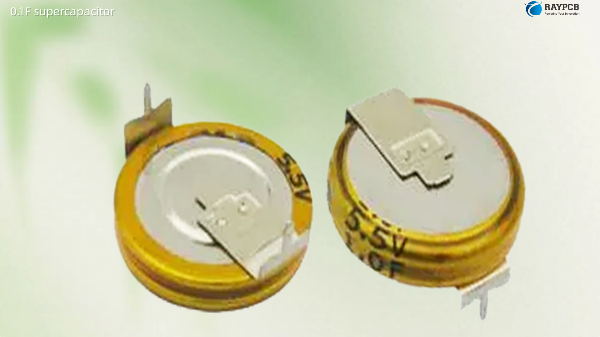
Coin Cell Form Factor

The traditional through-hole coin-cell supercapacitor โ€” physically resembling a large watch battery โ€” dominates in cost-sensitive designs like consumer appliances, home routers, industrial timers, and set-top boxes. Panasonic’s ML series and the KEMET FC series are the most widely stocked. These parts are polarized and must be installed with correct orientation. Typical ESR values run from a few ohms in very compact 0.1F parts down to under 100ฮฉ in better-specified 0.47F components โ€” high enough that peak current delivery is limited, but inconsequential for low-current RTC backup applications where peak current demand is measured in microamps.

SMD Chip Supercapacitor

SMD supercapacitors in 0805, 1206, and larger case sizes are available in the 0.1Fโ€“0.47F range from Murata (JUWT series), TDK (CPX series), and Taiyo Yuden. They allow fully automated SMT assembly without through-hole processes, which matters in high-volume consumer electronics manufacturing. Their footprint is larger than a 0402 or 0603 ceramic decoupling cap but comparable to a small electrolytic. The tradeoff is cost โ€” SMD supercapacitors at 0.22F typically cost two to five times more than equivalent through-hole coin types. In volume production at hundreds of thousands of units per year, this cost difference is significant; in low-volume industrial designs, it often isn’t.

Prismatic and Thin-Profile Types

CAP-XX and similar manufacturers offer thin prismatic supercapacitors in the 0.1Fโ€“0.47F range for applications where PCB height clearance is constrained โ€” handheld devices, wearables, thin embedded modules. These command a substantial premium and are specified in designs where form factor constraints explicitly override cost optimization.

RTC Backup Circuit Design: The Three Topologies Every Engineer Should Know

Topology 1: Simple Diode + Resistor (Low Cost, Lowest Complexity)

The most common RTC backup circuit connects the supercapacitor through a current-limiting resistor from the main VCC rail, with a diode preventing backfeed from the supercapacitor to the main rail when power is removed. The supercapacitor connects directly to the RTC VBAT pin.

Charging resistor value: R = (VCC โˆ’ V_cap_max) / I_charge_max

For a 3.3V supply charging a 5.5V-rated supercap (which we’ll cap at 3.0V for safety margin), with a desired charge current of 1mA: R = (3.3 โˆ’ 3.0) / 0.001 = 300ฮฉ.

The diode choice matters. A standard silicon diode drops 0.6โ€“0.7V, which means the supercapacitor charges to only VCC โˆ’ 0.7V, reducing available backup energy. A Schottky diode (BAT54, BAT85) with 0.3V forward voltage charges the cap closer to the rail voltage, delivering more usable energy. In 3.3V systems, this 400mV difference between Schottky and silicon diode translates to a meaningful percentage of the usable voltage window.

Topology 2: Ideal Diode / P-Channel FET Switch (Better Efficiency)

A P-channel MOSFET configured as an ideal diode eliminates the forward voltage drop of a physical diode, allowing the supercapacitor to charge all the way to VCC minus the FET’s on-state drop โ€” typically under 50mV at microamp currents. This is worth the additional component cost in systems where every millivolt of stored energy matters for backup duration. The gate drive circuit to switch the PMOS off when VCC falls below the cap voltage is simple: a resistor divider and a small signal NPN to pull the gate high when VCC disappears.

Topology 3: Dedicated Supercapacitor Charger IC (Best Control)

For designs where charge current control, cell balancing (for stacked 5.5V devices), and precise cutoff voltage management are needed, dedicated supercapacitor charger ICs from Texas Instruments (BQ33100), Maxim/ADI (MAX1505), and Linear Technology (LTC4425) provide clean, well-characterized charging behavior. These ICs include inrush current limiting, overvoltage protection, power-fail detection, and status outputs โ€” making them appropriate for designs where a failed backup charge would have serious consequences, such as industrial data loggers or automotive RTC modules.

For a more detailed treatment of how capacitors integrate into PCB power design including backup circuit layout considerations, reviewing board-level design guidelines before committing your layout is time well spent, especially around the placement and routing of the supercapacitor’s charge/discharge path.

Critical Design Pitfall: Leakage Current Kills Your Backup Time

The single most common reason small supercapacitor backup designs fail to meet backup time specifications in the field is underestimating total leakage and self-discharge current. Engineers calculate the backup time using only the RTC supply current from the IC datasheet, then discover the actual backup time is 30โ€“50% of what they calculated.

Self-discharge characteristics have a direct impact on backup time and must be considered alongside the RTC circuit’s supply current when sizing the supercapacitor. The total effective discharge current is the sum of the RTC supply current and the supercapacitor’s own self-discharge current, and for supercapacitors in the 0.1Fโ€“0.22F range, self-discharge current can easily match or exceed the RTC current.

Temperature compounds this problem significantly. Leakage current has a temperature dependency โ€” higher temperatures result in higher absorption current and leakage current. A 0.22F supercapacitor specified at 1ยตA leakage at 25ยฐC may draw 3โ€“5ยตA at 60ยฐC, which is a relevant consideration for designs installed in enclosures exposed to summer ambient temperatures or located near heat-generating components.

The practical mitigation: always calculate backup time using the worst-case sum of RTC supply current at maximum temperature plus the supercapacitor’s self-discharge current at the same temperature, with both values taken from the respective datasheets’ worst-case columns rather than typical values. Then add a 50% safety margin on top of that calculation.

Sizing the Supercapacitor: Step-by-Step Calculation

Here’s the complete calculation sequence for sizing a small supercapacitor for RTC or SRAM backup:

Step 1 โ€” Determine the total discharge current: I_total = I_RTC (from IC datasheet, worst-case at max temp) + I_selfdischarge (from supercap datasheet at max temp)

Step 2 โ€” Determine the usable voltage window: ฮ”V = V_charged โˆ’ V_cutoff V_charged = VCC โˆ’ V_diode_drop (or VCC with ideal diode topology) V_cutoff = minimum operating voltage of the RTC/SRAM IC (typically 1.0Vโ€“1.8V)

Step 3 โ€” Calculate required capacitance for desired backup time: C = I_total ร— t_backup / ฮ”V

Step 4 โ€” Apply a 1.5ร— to 2ร— safety margin: C_selected โ‰ฅ C ร— 1.5

Worked Example โ€” DS3231 RTC, 3.3V system, 7-day backup target:

  • I_RTC = 3ยตA (DS3231 worst case backup mode)
  • I_selfdischarge = 2ยตA (typical 0.22F coin supercap at 40ยฐC operating)
  • I_total = 5ยตA
  • ฮ”V = (3.3 โˆ’ 0.3) โˆ’ 1.0 = 2.0V (using Schottky diode, 1.0V cutoff)
  • t_backup = 7 days = 604,800 seconds
  • C = (5 ร— 10โปโถ ร— 604,800) / 2.0 = 1.51F

At 7-day backup with a DS3231, a 0.22F or even 0.47F supercapacitor is insufficient โ€” a 1.5F or 2F part is needed. This is exactly why datasheets recommending 0.22F for “weeks” of backup are based on RTCs drawing sub-1ยตA current, not the DS3231’s relatively hungry 3ยตA. Match the calculation to the specific IC being backed up.

Small Supercapacitor vs. Coin Cell Battery: When to Use Each

Criterion0.1Fโ€“0.47F SupercapacitorCR2032 Coin Cell Battery
Cycle life500,000+ cycles~500 cycles (charge) / one use (primary)
Charge/rechargeAutomatic from VCCRequires manual replacement
Self-discharge over yearsHigh โ€” months to emptyVery low โ€” 10-year shelf life
Energy capacityLow (mWh range)High (~225 mAh)
Backup duration at 1ยตA loadDays to weeksYears
Cost at volumeLow ($0.20โ€“$1.00)Low ($0.15โ€“$0.50)
RoHS / hazmat concernsNoneSome battery shipping restrictions
Failure modeGradual voltage decaySudden depletion
PCB integrationSoldered, no holder neededRequires battery holder or solder tabs
Suitable backup durationMinutes to weeksWeeks to years

The supercapacitor wins decisively on cycle life, elimination of battery replacement, automated charging from the main supply, and regulatory simplicity. The coin cell battery wins on energy density and shelf life. For products with 2+ year backup requirements, a coin cell or rechargeable lithium battery remains the right choice. For products with days-to-weeks backup requirements, automatic recharging, and high-volume manufacturing where a battery holder adds cost and assembly time, the 0.1Fโ€“0.47F supercapacitor is the better engineering answer.

PCB Layout Considerations for Small Supercapacitor Backup Circuits

Place the supercapacitor close to the VBAT pin. The RTC’s VBAT pin draws microamp currents, so resistance and inductance in the trace from the supercapacitor are not a practical concern โ€” but keeping the connection short protects against ESD coupling and board-level noise pickup on the sensitive backup supply node.

Keep the charge current path separate from the VBAT path. The charge resistor and series diode connect from the main VCC rail to the supercapacitor. If this trace is shared with the VBAT line running to the RTC, any noise on the VCC rail can couple directly into the backup circuit. Route the charge path and the VBAT supply trace as separate nets from the junction point, and place a small bypass ceramic (100nF) right at the RTC VBAT pin to ground.

Respect polarity. Supercapacitors are polarized components. Reversed polarity causes gas generation inside the cell, swelling, and potential rupture. Coin-cell form factor parts typically have the positive terminal marked with a “+” or a longer lead. SMD types have standard polarity marking per manufacturer convention. Mark polarity clearly in silkscreen and confirm it matches the footprint orientation.

Thermal placement. As noted above, leakage current increases substantially with temperature. Don’t place a backup supercapacitor adjacent to voltage regulators, switching MOSFETs, power resistors, or other heat-generating components. A few centimeters of separation from heat sources makes a measurable difference in actual backup time achieved in field conditions.

Series charging resistor placement. The current-limiting resistor should be placed in series between the main VCC rail and the supercapacitor, not between the supercapacitor and the VBAT pin. If the resistor is on the VBAT side, the resistive drop between the supercapacitor and the RTC will reduce available backup voltage and waste the energy advantage of having a low-dropout diode or ideal diode topology.

Useful Resources for Engineers Designing with Small Supercapacitors

Engineers working with 0.1Fโ€“0.47F supercapacitors in backup applications will find these manufacturer resources directly useful โ€” they go substantially deeper than the product pages:

KEMET Supercapacitor Application Notes (Mouser PDF) โ€” mouser.com/pdfDocs/KEMETSupercap_Leakage_Selfdischarge-Q3FY18.pdf: Authoritative treatment of the leakage vs. self-discharge distinction with measurement circuits, temperature curves, and a worked RTC backup example using the KEMET FC series.

Eaton Supercapacitors for RTC & Memory Backup Application Note โ€” eaton.com: Covers cell balancing in 5.5V stacked devices, backup time calculation methodology, and circuit topology comparison.

Murata SimSurfing Supercapacitor Selector โ€” murata.com/en-us/tool/simsurfing: Simulate impedance, self-discharge, and backup duration for Murata JUWT SMD supercapacitor series including the 0.1Fโ€“0.47F range.

Panasonic Industrial Supercapacitor Products โ€” industrial.panasonic.com: Panasonic ML series coin-type supercapacitors with full leakage current and self-discharge data โ€” a standard reference for RTC backup design.

Microchip Application Note โ€” Backup Power Sources for RTCCs and SRAMs โ€” microchip.com: Practical circuit examples for connecting supercapacitors to Microchip’s MCP79xxx RTC family, including diode and FET topologies with specific component recommendations.

Texas Instruments PMP9766 Supercapacitor Backup Reference Design โ€” ti.com/tool/PMP9766: Full reference design with schematics, BOM, and test data for a supercapacitor backup circuit using the TPS63020 buck-boost converter. Relevant for designs requiring regulated output voltage during backup.

Renesas Low Power Backup with Supercapacitor Reference Design โ€” renesas.com: ISL85403-based design supporting 3Vโ€“40V input range with supercapacitor energy extraction down to 0.3V.

Digikey Supercapacitor / EDLC Parametric Search โ€” digikey.com/en/products/filter/supercapacitors-ultracapacitors-edlcs: Filter by capacitance, voltage rating, ESR, form factor, and temperature range across multiple stocking brands. Useful for cross-referencing alternatives when a specific series is out of stock.

Frequently Asked Questions About 0.1F Supercapacitor Backup Design

Q1: Can I use a 0.1F supercapacitor to replace a CR2032 coin cell for RTC backup?

Sometimes yes, often no โ€” it depends entirely on the required backup duration and the RTC’s supply current. A CR2032 stores roughly 225mAh of energy; a 0.1F supercapacitor stores approximately 0.9mWh at 3V, which is orders of magnitude less. For an ultra-low-power RTC drawing 0.5ยตA or less, a 0.1F supercap can provide weeks of backup. For an RTC drawing 3ยตA or more, the same cap delivers only a few days. If your product requires months to years of backup power when unplugged, the CR2032 or a rechargeable lithium cell is the right choice. The supercapacitor’s advantage is automatic recharging from the main supply โ€” no manual battery replacement โ€” which suits products that are regularly powered on and need to survive only brief power interruptions.

Q2: My RTC backup time is much shorter than my calculation predicted. What’s going wrong?

The most common culprit is underestimating total discharge current. Check three things: first, verify you used the worst-case supply current from the RTC datasheet, not the typical value, and at your maximum operating temperature not at 25ยฐC. Second, obtain the self-discharge current for your specific supercapacitor from its datasheet โ€” many designs use only the RTC current in their calculation and ignore the cap’s own self-discharge, which may equal or exceed the RTC current. Third, verify your diode forward voltage drop hasn’t reduced the initial charged voltage more than you assumed, compressing the usable voltage window and reducing stored energy.

Q3: Why does my 5.5V rated supercapacitor use only 3.3V when my supply is 3.3V โ€” am I wasting most of its capacity?

Yes, but this is normal and expected. A supercapacitor’s voltage rating is the maximum it can safely be charged to, not a target operating voltage. In a 3.3V system, your supercapacitor charges to approximately 3.0V (with a Schottky diode drop) and discharges to the RTC’s minimum operating voltage (typically 1.0V to 1.8V). The energy stored is proportional to Vยฒ, so the usable energy is proportional to (V_chargedยฒ โˆ’ V_cutoffยฒ). Using a 5.5V rated part on a 3.3V supply only accesses roughly 30% of its maximum theoretical energy, but the 5.5V rating is chosen for its internal construction quality and to provide voltage derating margin, not because you’ll reach 5.5V in this circuit. A 2.7V rated coin supercap may actually be a better physical match for 3.3V systems if you use a Schottky diode โ€” just ensure the initial charged voltage never exceeds the 2.7V rating, which means VCC should be regulated below 3.0V at the charging node.

Q4: Can I connect two 0.22F supercapacitors in series to handle a higher voltage rail?

Yes โ€” two 0.22F supercapacitors in series produce an effective 0.11F capacitor rated at 5.4V (for 2.7V-rated cells) or 11V (for 5.5V-rated stacked cells). The total capacitance halves with series connection, and each cell sees only half the applied voltage. The critical consideration is cell voltage balancing: if the capacitors have different capacitances or leakage currents (which all real parts do to some degree), one cell will charge to a higher voltage than the other during charging, and the higher-charged cell may exceed its voltage rating. A passive balancing resistor across each cell (same resistance value for both) forces equalization โ€” but this resistor continuously draws current and shortens backup time. For designs requiring higher voltage operation, using a purpose-built 5.5V stacked two-cell supercapacitor from KEMET or Panasonic with internal cell balancing is cleaner than building series strings from individual cells.

Q5: How long does a small supercapacitor physically last, and will it degrade in service?

Supercapacitors don’t age the same way aluminum electrolytics do โ€” there’s no liquid electrolyte to evaporate and no oxide layer that degrades with reverse voltage. Rated cycle life for EDLCs in the 0.1Fโ€“0.47F range is typically 100,000 to 500,000 cycles, which is effectively unlimited for an RTC backup application that may cycle once per day. Shelf life at room temperature is typically rated at 10 years for stored, uncharged parts. Degradation in service shows up primarily as capacitance loss (typically 20โ€“30% after the rated operating period at maximum temperature) and slight ESR increase. For most RTC backup applications, neither matters much โ€” a 20% capacitance drop still leaves plenty of backup capacity. The conditions that genuinely shorten supercapacitor life are sustained operation at or above the maximum voltage rating and sustained operation at maximum temperature. Staying within the voltage rating with appropriate derating and keeping the device cool are the two most impactful things you can do for long field life.

Summary

The 0.1F supercapacitor and its siblings in the 0.22F and 0.47F range occupy a specific, well-defined niche in PCB power design: automatic, maintenance-free backup power for low-current RTCs and SRAMs, covering backup durations from hours to weeks without batteries, battery holders, or manual replacement procedures. Sizing them correctly requires accounting for both RTC supply current and supercapacitor self-discharge current at maximum operating temperature, applying a meaningful safety margin, and selecting the right circuit topology โ€” diode-resistor for simplicity, PMOS ideal diode for efficiency, or dedicated charger IC for critical applications. Get those fundamentals right, choose a quality component from KEMET, Panasonic, Murata, or Eaton, and keep it cool and within its voltage rating, and this deceptively simple component will run silently and reliably for the life of your product.

All technical values cited are representative of typical parts at time of writing. Always verify specifications against current manufacturer datasheets for your selected component series.

470nF Capacitor: Code 474 โ€” Filtering, Timing & PSU Uses

470nF Capacitor in Filtering”, “Timing Circuits”, “Power Supply Units”, “PCB Layout” all anchor headings

The 470nF capacitor is one of those unassuming components that ends up in more circuit types than most engineers initially expect. It bridges the gap between the high-frequency ceramic bypass caps (think 100nF and below) and the low-frequency bulk electrolytics (1ยตF and above), making it genuinely useful in AC filtering stages, RC timing networks, power supply decoupling, snubber circuits, and signal coupling in audio systems. If you’ve stared at a yellow film cap or a small monolithic ceramic part stamped 474J and wondered what the code means, you’re in the right place.

Decoding the 474 Code: What Is a 470nF Capacitor?

How to Read the 3-Digit Capacitor Code

The three-digit stamping system on ceramic, film, and tantalum capacitors follows a consistent rule. The first two digits give the significant figures, the third digit is the power-of-ten multiplier, and the result is always in picofarads (pF).

For code 474:

  • First two digits: 47
  • Third digit: 4ย โ†’ multiply by 10โด = 10,000
  • Result: 47 ร— 10,000 = 470,000 pF = 470 nF = 0.47 ยตF

So a capacitor stamped 474J decodes as: 47 ร— 10,000 = 470,000 pF = 470 nF or 0.47 ยตF at ยฑ5% tolerance (J suffix). This is one of the more frequently confused codes โ€” engineers who know the 473 code (47nF) sometimes misread 474 as being just one step higher in value, not realizing the jump is ร—10. Always verify before substituting.

Code 474 vs Neighboring Values

CodeCapacitanceAlso Written As
4724.7 nF4,700 pF
47347 nF0.047 ยตF
474470 nF0.47 ยตF / 470,000 pF
4754.7 ยตF4,700 nF
47647 ยตF47,000 nF

This makes it obvious why the 473 vs 474 mix-up is so costly โ€” substituting one for the other is a 10ร— error in capacitance, which will completely change the behavior of a timing circuit or filter stage.

Tolerance Letters on the 470nF Capacitor

SuffixToleranceWhen to Use
Jยฑ5%Timing circuits, precision RC filters
Kยฑ10%General decoupling, filtering, PSU bypassing
Mยฑ20%Non-critical bypass applications

A 474J cap gives you 470nF ยฑ23.5nF โ€” acceptable for most filtering and timing duties. If you receive 474K parts when you ordered 474J, the difference for a decoupling application is effectively negligible. For timing-critical designs, however, stick to J grade.

470nF Capacitor Specifications and Dielectric Types

Available Dielectric Options

The 470nF capacitor is available in multiple dielectric technologies, and choosing the right one for your specific application genuinely matters.

X7R Ceramic (MLCC): The most common 470nF part on supplier catalogs. Monolithic construction provides excellent temperature stability, low loss, and high reliability compared to standard ceramic capacitors. This non-polarized capacitor is rated at 50V and is ideal for decoupling, bypassing, filtering, and timing applications. X7R capacitance drifts ยฑ15% over the full โˆ’55ยฐC to +125ยฐC temperature range and also shifts with applied DC voltage. Fine for power supply bypass but avoid it in precision timing where stability matters.

C0G / NP0 Ceramic: Excellent temperature stability and low dielectric losses, making these ideal for RF, resonant circuits, and precision filters. At 470nF, C0G parts are physically larger and more expensive than X7R equivalents but are the correct choice wherever the capacitance value needs to remain stable across temperature and voltage.

Polyester Film (PET / Mylar): The 470nF polyester film capacitor is a non-polarized capacitor using polyester film as its dielectric material. It delivers stable electrical performance, low leakage current, and long service life, making it suitable for signal coupling, filtering, and noise suppression applications. Voltage ratings of 100V, 250V, and 400V are common in radial-lead through-hole packages. The 474J 470nF 100V version in box-type epoxy casing is particularly popular for energy correction, signal filtering, and bypass applications in both analog and digital circuits.

Polypropylene Film: Best-in-class dielectric absorption performance. Available in high-voltage variants rated at 450V and 630V โ€” a 470nF 450V polypropylene film cap is specifically suited to high-power applications. The tradeoff is physical size and cost.

Specification Comparison Table

DielectricCapacitanceVoltage RatingToleranceBest Application
X7R Ceramic (0603)470 nF10V โ€“ 50Vยฑ10% KSMD decoupling, MCU bypass
X7R Ceramic (0805)470 nF25V โ€“ 100Vยฑ10% KGeneral SMD filtering
Polyester Film470 nF100V โ€“ 400Vยฑ5โ€“10%Signal coupling, audio, PSU
Polypropylene470 nF250V โ€“ 630Vยฑ5% JHigh-voltage snubbers, audio
Monolithic Ceramic470 nF50V โ€“ 100Vยฑ10% KBypass, decoupling, timing

The 470nF Capacitor in Filtering Applications

Where 470nF Fits in the Frequency Spectrum

A lot of engineers default to 100nF for decoupling and jump straight to 10ยตF electrolytics for bulk supply filtering, leaving a useful middle ground uncovered. The 470nF capacitor fills that gap. Its self-resonant frequency (SRF) โ€” where it transitions from capacitive to inductive behavior โ€” sits comfortably in the 1โ€“5 MHz range for through-hole film parts and higher for 0603/0805 MLCC packages. That makes it effective at filtering noise in the tens-of-kilohertz to low-megahertz range that 100nF caps handle poorly and electrolytics simply can’t reach.

RC Filter Cutoff Frequencies with 470nF

Using the standard formula f = 1 / (2ฯ€ ร— R ร— C) with C = 470nF (0.00000047 F):

Resistor ValueCutoff Frequency (-3dB)Practical Application
10 ฮฉ~33.9 kHzOutput EMI filter, switching PSU
100 ฮฉ~3.4 kHzAudio low-pass, anti-aliasing
330 ฮฉ~1.03 kHzAudio crossover mid frequency
1 kฮฉ~339 HzBass rolloff, sub-woofer filter
3.3 kฮฉ~102 HzPower line frequency filtering
10 kฮฉ~33.9 HzVery-low-frequency rejection
33 kฮฉ~10.2 HzNear-DC coupling and blocking

These values make the 470nF a natural fit for audio-band low-pass filters, anti-aliasing stages ahead of ADCs sampling in the tens-of-kHz range, and AC-line EMI rejection in power supply input stages.

470nF Capacitor in Timing Circuits

RC Time Constants and the 555 Timer

The RC time constant formula is simply ฯ„ = R ร— C. With a 470nF capacitor, here’s what common resistor values produce:

Resistor ValueRC Time Constant (ฯ„)555 Monostable Pulse Width (T = 1.1RC)
1 kฮฉ470 ยตs~517 ยตs
4.7 kฮฉ2.21 ms~2.43 ms
10 kฮฉ4.7 ms~5.17 ms
47 kฮฉ22.1 ms~24.3 ms
100 kฮฉ47 ms~51.7 ms
470 kฮฉ221 ms~243 ms (โ‰ˆ ยผ second)
1 Mฮฉ470 ms~517 ms (โ‰ˆ ยฝ second)

The 555 timer IC monostable output pulse width is calculated as T = 1.1 ร— R ร— C โ€” a 470nF capacitor paired with a 470kฮฉ resistor gives approximately 243 milliseconds, which is handy for LED flash timers, switch debounce circuits, and relay delay applications without needing a large electrolytic capacitor. Unlike electrolytics, film capacitors have far lower leakage current, so a 470nF film cap with a high-value resistor gives noticeably more accurate timing than an electrolytic of equivalent value.

Why Avoid Electrolytic Capacitors in Timing Circuits?

This is worth spelling out clearly. Electrolytic capacitors have significant leakage current that causes the effective charge/discharge time to differ from the theoretical calculation โ€” particularly at higher resistor values where the leakage represents a meaningful fraction of the current flowing through the timing resistor. A 470nF polyester film capacitor avoids this problem entirely. It’s non-polarized, has very low leakage, and will maintain timing accuracy well within the J-grade ยฑ5% tolerance over the operating temperature range.

470nF Capacitor in Power Supply Units (PSU)

PSU Input Stage Filtering and X-Capacitors

In AC mains power supply designs, capacitors connected directly across the AC input line to suppress differential-mode conducted EMI are known as X-capacitors. A 470nF X2-rated film capacitor at the mains input is a common specification in switch-mode power supplies and motor drives. The X2 rating indicates the capacitor is specifically approved for use across the mains line, with defined failure modes that don’t create a shock hazard. These parts typically carry IEC 60384-14 certification and are rated for 250V AC or 305V AC continuous operation.

Output Stage Decoupling and Ripple Filtering

A capacitor on a PCB at the output stage of a linear or switching regulator serves a different purpose from the bulk electrolytic. Where the bulk cap handles low-frequency ripple, a 470nF ceramic or film cap placed close to the output pin handles the higher-frequency transients that the electrolytic misses due to its own parasitic inductance at frequencies above a few hundred kHz. The combination of a 47ยตF or 100ยตF electrolytic in parallel with a 470nF ceramic provides substantially lower impedance across a wider bandwidth than either part alone.

Snubber and Transient Suppression Roles

Across diode and MOSFET junctions in a switching power supply, a 470nF capacitor in series with a damping resistor forms a classic RC snubber. The capacitor absorbs the energy stored in circuit parasitic inductance during switch-off transitions, preventing voltage spikes that would otherwise stress the switching device. A 470nF polypropylene film cap rated at 630V has enough headroom for most off-line flyback and forward converter topologies operating from a 230V AC rectified rail. At high frequencies, multilayer capacitors exhibit low ESR and find conventional use as snubbers or filters in telecommunications, medical, military, and aerospace equipment.

PCB Layout Considerations for 470nF Capacitors

Through-Hole vs SMD: Making the Right Choice

Through-hole 470nF film capacitors are the correct pick whenever you need the higher voltage ratings (250V+), lower dielectric absorption (polypropylene), or non-polarized signal-path coupling. The main PCB layout consideration is lead spacing โ€” radial 474 film caps come in 5mm, 7.5mm, and 10mm pitch variants. Getting this wrong on your footprint means reworking leads manually or spinning the board, so always verify the datasheet before finalizing the PCB footprint.

For standard 5V/3.3V digital supply bypass duty, 0603 or 0805 SMD MLCC 470nF parts make more engineering and manufacturing sense. Their low ESL (roughly 0.5โ€“1.5 nH for 0603 parts) pushes the self-resonant frequency well above 10 MHz, and their small footprint allows placement within 1โ€“2 mm of IC power pins where bypass performance is maximized.

Multi-Layer Ceramic Capacitors: Beware DC Bias Derating

This catches engineers off guard more often than it should. An X7R 470nF MLCC rated at 10V will lose 30โ€“50% of its nominal capacitance at 5V due to DC bias derating โ€” meaning your effective bypass capacitance is closer to 250โ€“330nF under typical operating conditions. For critical filtering applications, either specify a higher voltage rating (a 25V or 50V part on a 5V rail retains nearly full capacitance) or use a C0G dielectric which doesn’t exhibit this behavior.

Useful Resources for 470nF Capacitor Selection

  • Capacitor Code Calculator:ย kiloohm.info/3-digit-capacitor/474ย โ€” Decode or encode any 3-digit capacitor code including 474
  • Murata SimSurfing:ย product.murata.com/en-global/tools/simsurfingย โ€” Plot actual impedance vs. frequency curves for 470nF MLCCs including DC bias derating
  • KEMET Component Selector:ย kemet.comย โ€” Comprehensive catalog of film and ceramic 470nF capacitors with full datasheets and SPICE models
  • WIMA Film Capacitor Catalog:ย wima.deย โ€” Premium German film capacitors; the MKS2 and MKP series cover 470nF in multiple voltage and lead spacing options
  • 555 Timer Calculator (Digi-Key):ย digi-key.com/en/resources/conversion-calculators/conversion-calculator-555-timerย โ€” Calculate timing intervals with 470nF for monostable and astable 555 configurations
  • IEC 60384-14 Standard Referenceย โ€” The governing document for X-capacitor and Y-capacitor ratings in AC mains applications

Frequently Asked Questions About the 470nF Capacitor

Q1: What does a capacitor marked 474 mean, and what is its actual value? Code 474 decodes as 47 ร— 10โด pF = 470,000 pF = 470 nF = 0.47 ยตF. These four notations describe the exact same capacitance value. If a supplier’s catalog shows “0.47ยตF 474J”, it is referring to this same part. The letter J at the end indicates ยฑ5% tolerance, K indicates ยฑ10%.

Q2: Can I replace a 474J capacitor with a 474K in an audio circuit? The tolerance difference between J (ยฑ5%) and K (ยฑ10%) represents a maximum spread of only 47nF for this value โ€” from 423nF to 517nF for K grade vs 447nF to 493nF for J grade. In most audio signal coupling and filter applications, this difference is inaudible and the K-grade substitution is electrically sound. Where the cap is setting a specific RC corner frequency or timing interval that is close to a performance boundary, stick with J grade.

Q3: Is a 470nF capacitor polarized? No. Whether ceramic, polyester film, or polypropylene, 470nF capacitors are non-polarized and can be installed in either orientation on a PCB. This makes them directly suitable for AC signal path coupling, crossover networks, and AC mains X-capacitor applications where polarized electrolytics cannot be used. Always confirm that an X-rated film capacitor carries the appropriate safety certification before deploying it across AC mains lines.

Q4: What is the difference between a 470nF capacitor and a 0.47ยตF capacitor? They are exactly the same value expressed in different units. 470 nanofarads = 0.47 microfarads = 470,000 picofarads. Supplier catalogs and datasheets use all three notations interchangeably, which causes confusion when searching for parts. When placing orders, entering “0.47ยตF” and “470nF” in a supplier’s search field should return identical results for the same capacitor type.

Q5: Why does my 470nF X7R MLCC measure significantly less than 470nF on my bench meter? Two main reasons. First, DC bias derating: if you’re measuring with a DC bias applied (as would occur in circuit), an X7R MLCC rated at 10V can lose 40โ€“50% of capacitance at voltages above half its rating. Second, capacitance meters typically measure at a fixed low-voltage AC test signal (often 1V RMS at 1kHz), which doesn’t reflect real-world circuit behavior with a DC supply rail. The solution is to either specify a higher-voltage-rated MLCC โ€” a 25V part on a 5V rail retains close to its full capacitance โ€” or switch to C0G dielectric, which shows negligible voltage-dependent capacitance change.

The 470nF capacitor punches well above its weight class. From RC timing networks producing quarter-second pulses with nothing but a resistor, to X-capacitor EMI filtering at the AC mains input, to power supply output decoupling that electrolytics can’t cover โ€” it’s the kind of component that rewards engineers who understand exactly what it’s doing and exactly where it belongs on the board.

220 nF Capacitor: Code 224 & Power Rail Filtering Uses

220nF capacitor guide: decode the 224 marking, explore power rail filtering uses, compare dielectrics, calculate RC cutoffs & get 5 FAQs answered.

The 220nF capacitor doesn’t get the same spotlight as its 100nF or 1ยตF siblings, but it’s a value I reach for more often than most people expect. Sitting right between the universal 100nF bypass cap and the bulkier 470nF, the 220nF (0.22ยตF) value fills a practical gap in power rail filtering, EMI suppression, and analog signal conditioning that the more popular values sometimes can’t cover efficiently on their own.

In this guide, I’ll break down the code, the specs, the applications, and the specific situations where a 220nF capacitor is the right call on your board.

Decoding the 224 Capacitor Marking

The “224” code on a ceramic or film capacitor follows the standard three-digit system. The first two digits (22) are the significant figures. The third digit (4) is the multiplier โ€” the number of zeros to append, with the result in picofarads.

22 ร— 10โด = 220,000 pF = 220 nF = 0.22 ยตF

Here’s a quick conversion reference so you can match it however your datasheet or BOM lists it:

UnitValue
Picofarads (pF)220,000 pF
Nanofarads (nF)220 nF
Microfarads (ยตF)0.22 ยตF

You’ll see “0.22ยตF” on American datasheets, “220nF” on European ones, and sometimes just “.22” on older schematics. They all refer to the same 220nF capacitor.

Tolerance Codes You’ll See on 224 Parts

LetterToleranceNotes
Jยฑ5%Precision filters, timing
Kยฑ10%General-purpose (most common)
Mยฑ20%Non-critical bypass

For filtering and decoupling work, 224K (ยฑ10%) covers nearly every use case I’ve encountered. If you’re using the 220nF capacitor in a precision RC network or audio tone circuit, step up to the J-tolerance part.

Where the 220nF Capacitor Fits in the E-Series

The 220nF value belongs to the E12 preferred number series (specifically the “22” decade step). It fills the gap between 100nF (104) and 470nF (474) in the standard capacitor value lineup. Here’s how it sits in context:

CodeValueCommon Role
104100 nFStandard IC decoupling
224220 nFEnhanced filtering, power rail smoothing
334330 nFMid-range filtering
474470 nFBulk local bypass
1051 ยตFBulk decoupling

That “in-between” position is exactly why the 220nF capacitor is useful. When 100nF isn’t quite enough local capacitance but 1ยตF is overkill or physically too large in the dielectric you need, 220nF slots in perfectly.

Practical Applications for the 220nF Capacitor

Power Rail Filtering and Enhanced Decoupling

This is the primary reason I place 220nF capacitors on boards. In designs with moderately noisy power rails โ€” think DC-DC converter outputs, mixed-signal boards, or motor driver supplies โ€” a 100nF decoupling cap alone sometimes isn’t enough local capacitance to absorb the transient current demands from an IC.

Adding a 220nF capacitor in parallel with the standard 100nF provides roughly double the charge reservoir without the DC bias derating concerns you’d face jumping straight to 1ยตF in a small MLCC package. For X7R dielectric parts, a 220nF in an 0402 or 0603 package retains its capacitance under bias much better than a 1ยตF in the same footprint.

EMI Input Filters and X-Capacitors

In AC mains applications, the 220nF capacitor shows up regularly as an X2-rated safety capacitor for differential-mode EMI suppression. Placed line-to-neutral in an input filter, a 220nF X2 cap provides higher attenuation than the more common 100nF X2, particularly at lower interference frequencies in the 150 kHzโ€“1 MHz conducted emissions band where CISPR standards have the strictest limits.

If you’ve ever struggled to pass conducted emissions testing with a 100nF X-cap, bumping to 220nF is often the simplest fix before resorting to larger inductors.

RC Low-Pass Filters

Paired with a resistor, the 220nF capacitor creates useful cutoff frequencies for sensor conditioning and audio-range filtering:

Resistor (R)Cutoff Frequency (f_c)
1 kฮฉโ‰ˆ 723 Hz
4.7 kฮฉโ‰ˆ 154 Hz
10 kฮฉโ‰ˆ 72.3 Hz
47 kฮฉโ‰ˆ 15.4 Hz
100 kฮฉโ‰ˆ 7.2 Hz

Those sub-100 Hz cutoff frequencies with reasonable resistor values make the 220nF capacitor a solid choice for filtering slow-changing analog signals โ€” temperature sensors, strain gauges, battery voltage monitoring โ€” without needing resistor values so high that they introduce significant noise or bias current errors.

Audio Coupling and Tone Shaping

In audio circuits, 220nF is a popular coupling capacitor value, especially in guitar pedal and synthesizer designs. It passes frequencies above roughly 70โ€“150 Hz (depending on load impedance) while rolling off the low bass, which is useful for taming muddiness in preamp stages or setting the character of a high-pass filter in a tone stack.

Film capacitors at 220nF โ€” polyester or polypropylene types marked “2A224J” or similar โ€” are the preferred choice here because they introduce less distortion and microphonic noise compared to ceramic alternatives.

Choosing the Right 220nF Capacitor for Your Design

Dielectric and Package Selection

DielectricBest ForWatch Out For
X7R (ceramic)General decoupling, power rail filteringCapacitance drops under DC bias
C0G / NP0 (ceramic)Precision filters, timingLarge package for 220nF; limited availability
Polyester filmAudio coupling, AC filtering, X2 safety capsPhysically larger; not for high-density SMD
X5R (ceramic)Low-voltage, space-constrainedNarrower temp range (โˆ’55ยฐC to +85ยฐC)

For SMD power rail filtering, X7R in 0603 or 0805 is my default pick. For audio or AC mains work, I’ll use a polyester film type. The 220nF value is small enough that C0G/NP0 ceramic options do exist, but they tend to require 0805 or 1206 packages โ€” worth it only if you’re building a precision analog filter where dielectric stability really matters.

Voltage Rating Guidelines

ApplicationMinimum Rating
3.3V / 5V logic16V or 25V
12V systems50V
24V industrial50V or 100V
AC mains (X2 safety cap)275VAC rated

Same rule as always: derate by at least 2ร— your working voltage for ceramic types to maintain actual capacitance near the nominal 220nF.

Useful Resources

ResourceDescriptionLink
Murata SimSurfingMLCC impedance and DC bias simulationmurata.com
KEMET K-SIMCapacitor simulation toolkemet.com
DigiKey RC Filter CalculatorCutoff frequency calculatordigikey.com
Capacitor Code Chart (PDF)Printable 3-digit code referencesynthrotek.com
TDK Product CenterSearchable MLCC specs and datasheetsproduct.tdk.com
MIT Capacitor Codes ReferenceConcise code decoding guideweb.mit.edu

Frequently Asked Questions About the 220nF Capacitor

What does the code 224 mean on a capacitor?

The code 224 means 22 ร— 10โด picofarads = 220,000 pF = 220 nF (0.22 ยตF). The first two digits are the significant figures and the third digit is the power-of-ten multiplier, with the result expressed in picofarads.

Can I substitute a 220nF capacitor with 100nF or 470nF?

It depends on the circuit. For general decoupling, either neighbor value will usually work. However, in RC timing circuits, precision filters, or EMI filter designs where the capacitance directly sets a cutoff frequency or attenuation level, substituting will shift the circuit’s behavior. A 100nF cap provides half the capacitance (higher cutoff), while 470nF provides roughly double (lower cutoff). Always check whether the application is sensitive to the exact value before swapping.

Is a 220nF capacitor polarized?

No. At 220nF, the vast majority of available parts are ceramic MLCCs or polyester film capacitors, both of which are non-polarized. You can install them in any orientation. Electrolytic and tantalum types aren’t manufactured at values this small.

What is the best dielectric for a 220nF decoupling capacitor?

For power rail decoupling on a PCB, X7R ceramic is the standard choice. It offers good stability across the โˆ’55ยฐC to +125ยฐC range and is available in compact SMD packages. For audio coupling or AC line filtering, polyester or polypropylene film capacitors are preferred because of their lower distortion and self-healing properties.

Why would I choose 220nF over the standard 100nF for decoupling?

The 220nF capacitor provides more than twice the charge storage while still fitting in the same small SMD footprint (0603 or even 0402 in some product lines). This extra capacitance helps on noisier power rails โ€” downstream of switching regulators, near motor drivers, or in mixed-signal designs where 100nF alone doesn’t provide enough local energy to keep the supply voltage clean during heavy transient loads.

Wrapping Up

The 220nF capacitor isn’t the first value that comes to mind when most engineers think about passive components, but that’s precisely what makes it useful โ€” it fills the gaps that the more common values leave behind. Whether you’re beefing up a decoupling network, tuning an EMI input filter to pass conducted emissions, or setting a low-frequency cutoff in an analog signal path, the 224-coded cap is a practical, cost-effective solution that belongs in every well-stocked parts library.

100 nF (0.1 ยตF) Capacitor: The Most Important Decoupling Capacitor in Electronics

100nF capacitor explained by a PCB engineer โ€” decode the 104 marking, master decoupling placement, compare dielectrics, and explore modern alternatives.

Ask any PCB engineer which single component they place more than any other, and the answer is almost always the same: the 100nF capacitor. Marked with the code 104, this humble ceramic cap has been the default decoupling choice since the early days of digital ICs, and it remains the most frequently specified capacitor in electronics design today.

In this guide, I’ll cover everything you need to know about the 100nF capacitor โ€” from reading the code on the part to understanding why this particular value became the industry standard, and how modern advances are starting to challenge its dominance.

What Is a 100nF Capacitor?

A 100nF capacitor stores 100 nanofarads of electrical charge. You’ll encounter this value written in several equivalent ways depending on the datasheet, distributor, or region:

UnitValue
Picofarads (pF)100,000 pF
Nanofarads (nF)100 nF
Microfarads (ยตF)0.1 ยตF
Farads (F)100 ร— 10โปโน F

If a schematic says “0.1ยตF” and your BOM says “100nF,” don’t panic โ€” they’re the same part. American datasheets and older schematics tend to use 0.1ยตF notation, while European documentation usually favors 100nF. Both refer to the exact same 100nF capacitor.

How to Read the 104 Capacitor Code

The “104” marking printed on ceramic capacitors follows the standard three-digit coding system. The first two digits (10) are the significant figures. The third digit (4) is the multiplier โ€” it tells you how many zeros to append, with the final result in picofarads.

So: 10 ร— 10โด = 100,000 pF = 100 nF = 0.1 ยตF.

Tolerance Letter Codes on 100nF Capacitors

You’ll sometimes see a letter after “104” on the component body. That letter tells you the capacitance tolerance:

LetterToleranceTypical Use
Jยฑ5%Precision filtering, timing
Kยฑ10%General decoupling (most common)
Mยฑ20%Non-critical bypass
Z+80% / โˆ’20%Budget, non-critical

For decoupling duty, 104K (ยฑ10%) is what you’ll find on the vast majority of BOMs. The ยฑ5% J-tolerance parts cost slightly more and are reserved for designs where the exact capacitance value matters โ€” like a precision RC filter or an oscillator feedback network.

Why 100nF Became the Standard Decoupling Value

This is a question I’ve been asked countless times by junior engineers, and the history behind it is worth understanding.

When digital ICs started proliferating in the 1970s and 1980s, engineers needed a capacitor that could sit next to each chip’s power pins and absorb the high-frequency current spikes generated by fast logic transitions. The 100nF ceramic disc capacitor was, at the time, a practical and economical choice. It was the largest value readily available in small ceramic packages, and its self-resonant frequency (SRF) sat comfortably above the clock speeds of the logic families being used.

As ICs got faster, the 100nF capacitor transitioned from a bulky through-hole disc to a tiny surface-mount MLCC in 0603 or 0402 packages. That shrinkage naturally raised its SRF, keeping it relevant for each successive generation of digital hardware. The datasheets kept recommending it, the reference designs kept including it, and an entire generation of engineers learned the rule: “put a 100nF cap on every power pin.”

That rule has stuck โ€” and for most practical designs, it still works well. But as we’ll discuss later, it’s worth understanding when 100nF might not be the optimal choice anymore.

Key Specifications When Selecting a 100nF Capacitor

Slapping any “104” cap onto your board without checking the specs is a fast path to noise problems, failed EMC testing, or field reliability issues. Here are the parameters I always verify.

Voltage Rating

The voltage rating defines the maximum continuous DC voltage the 100nF capacitor can withstand. Common ratings for MLCC versions include 10V, 16V, 25V, 50V, and 100V.

Circuit VoltageRecommended Cap Rating
3.3V digital logic16V or 25V
5V systems25V
12V power rails50V
24V industrial50V or 100V
General prototyping50V (safe default)

My standing rule: select at least 2ร— your maximum operating voltage. This isn’t just about safety margin โ€” with X7R and X5R dielectrics, the effective capacitance drops significantly under DC bias. A 100nF X7R cap rated at 16V might only deliver 60โ€“70nF when you apply 10V across it. Overrating the voltage keeps your actual capacitance closer to the nominal 100nF.

Dielectric Material

The dielectric type determines how the 100nF capacitor behaves across temperature, frequency, and applied voltage. This is critical for PCB designs.

DielectricTemp RangeCapacitance StabilityBest Application
C0G / NP0โˆ’55ยฐC to +125ยฐCยฑ30 ppm/ยฐCPrecision analog, RF (rarely available at 100nF in small packages)
X7Rโˆ’55ยฐC to +125ยฐCยฑ15%Decoupling, filtering โ€” the workhorse
X5Rโˆ’55ยฐC to +85ยฐCยฑ15%Low-voltage decoupling
Y5Vโˆ’30ยฐC to +85ยฐC+22% / โˆ’82%Avoid for decoupling

For 100nF decoupling, X7R is the default choice. It offers stable performance across a wide temperature range and is available in every package size from 0201 up to 1206. X5R is acceptable for low-voltage, room-temperature applications. Y5V is genuinely terrible for decoupling โ€” the capacitance can swing wildly with temperature and bias, which defeats the purpose entirely.

C0G at 100nF does exist, but typically requires larger packages (0805 or 1206), which increases parasitic inductance and reduces high-frequency effectiveness. It’s a tradeoff that rarely makes sense for bypass duty.

SMD Package Sizes for 100nF Capacitors

The 100nF capacitor is manufactured in every standard SMD package. Your choice depends on board density, assembly process, and voltage requirements.

PackageDimensions (mm)Notes
02010.6 ร— 0.3Highest density; limited voltage ratings
04021.0 ร— 0.5Sweet spot for modern high-density PCBs
06031.6 ร— 0.8Excellent all-rounder; easy to hand-solder
08052.0 ร— 1.25Prototyping-friendly; good for higher voltages
12063.2 ร— 1.6High-voltage versions; power applications

For most new designs targeting automated SMT assembly, I default to 0402 for 100nF decoupling caps. The small footprint keeps the cap physically close to the IC pin โ€” which directly reduces parasitic loop inductance and improves high-frequency performance. If hand-soldering or prototyping is in the picture, 0603 is the smallest I’d recommend for sanity’s sake.

Where the 100nF Capacitor Gets Used in Real Circuits

IC Power Pin Decoupling

This is the primary role of the 100nF capacitor, and the reason it appears dozens or even hundreds of times on a single board. Every digital IC โ€” microcontrollers, FPGAs, memory chips, interface transceivers โ€” needs local charge storage right at its power pins.

When a logic gate switches state, it draws a brief burst of current from the supply rail. That current spike has to come from somewhere close by, because the inductance of long PCB traces and connector pins means the main power supply can’t respond fast enough. The 100nF capacitor, sitting within a few millimeters of the power pin, acts as a local energy reservoir that supplies this instantaneous current and smooths out the resulting voltage dip.

Multi-Value Decoupling Strategy

Experienced designers rarely rely on a single 100nF capacitor alone. The common practice is a multi-value approach combining different capacitance values to cover a wider frequency range:

Capacitor ValueTarget Frequency RangeRole
10 ยตF (bulk)Below 1 MHzLow-frequency transient supply
1 ยตF1 MHz โ€“ 10 MHzMid-frequency filtering
100 nF5 MHz โ€“ 50 MHzPrimary decoupling
10 nF30 MHz โ€“ 200 MHz+High-frequency bypass

Each value has a different self-resonant frequency, and the combination creates a low-impedance power delivery network across a broad spectrum. The 100nF capacitor covers the critical middle ground where most digital switching noise lives.

That said, there’s an ongoing debate in the engineering community about whether this multi-value approach is still necessary with modern MLCCs. Since ESL (equivalent series inductance) is primarily determined by the physical package โ€” not the capacitance value โ€” two capacitors in the same 0402 package will have nearly identical ESL regardless of whether they’re 10nF or 1ยตF. This means a single 1ยตF cap in a small package can often outperform the traditional 100nF + 10nF combination across the entire frequency range. It’s worth running impedance simulations for your specific design rather than blindly following legacy rules.

Op-Amp and Analog IC Bypassing

For analog circuits, the 100nF capacitor serves as the standard bypass cap on op-amp supply pins. Most op-amp datasheets explicitly recommend placing a 100nF ceramic cap between each supply pin and ground, as close to the package as possible. Some designs add a 10ยตF electrolytic or tantalum in parallel for additional low-frequency filtering, especially in audio paths.

Signal Filtering and RC Networks

Paired with a resistor, a 100nF capacitor creates a simple first-order low-pass filter. The cutoff frequency follows the standard formula: f_c = 1 / (2ฯ€ ร— R ร— C).

Resistor ValueCutoff Frequency
1 kฮฉโ‰ˆ 1.59 kHz
10 kฮฉโ‰ˆ 159 Hz
47 kฮฉโ‰ˆ 33.9 Hz
100 kฮฉโ‰ˆ 15.9 Hz

These cutoff frequencies make the 100nF capacitor useful for audio-range low-pass filtering, sensor signal smoothing, and slow-changing analog signal conditioning.

EMI Filtering and Compliance

In EMC-sensitive designs, 100nF capacitors placed at board entry points, connector pins, and cable interfaces help suppress conducted high-frequency emissions. Combined with ferrite beads in a pi-filter configuration, they form effective EMI barriers that can make the difference between passing and failing radiated emissions testing.

Placement Best Practices for 100nF Decoupling Caps

Getting the placement right matters more than most engineers realize. Here are the rules I follow on every layout:

Place the capacitor within 2โ€“3mm of the IC power pin. Every extra millimeter of trace adds parasitic inductance that degrades high-frequency decoupling performance. The via connecting the cap’s ground pad to the ground plane should be equally short.

Route the connection through the capacitor first. Ideally, the power trace should flow from the supply, through the capacitor pads, and then to the IC pin. This forces high-frequency current to flow through the capacitor rather than around it.

Use multiple vias to ground. A single via adds roughly 0.5โ€“1 nH of inductance. Two vias in parallel cut that in half. For high-speed designs, use as many ground vias as the footprint allows.

Don’t share decoupling caps between ICs. Each IC should have its own dedicated 100nF capacitor on each power pin. Sharing defeats the purpose of local energy storage.

The Modern Debate: Is 100nF Still the Best Choice?

This is a conversation that has picked up momentum over the past couple of years, and I think it’s healthy for the industry.

The core argument is that modern MLCCs in small packages (0402, 0201) can deliver 1ยตF or even 2.2ยตF with the same ESL as a 100nF cap in the same package. Since a larger capacitance provides lower impedance at most frequencies of interest, a 1ยตF cap is objectively better at decoupling across a wider bandwidth โ€” at roughly the same cost and in the same footprint.

So why does 100nF persist? Partly inertia and partly because IC datasheets still recommend it. Most chip manufacturers validate their reference designs with 100nF decoupling, and deviating from the datasheet recommendation introduces risk โ€” especially in safety-critical or certification-sensitive products. For hobby projects, prototypes, and general embedded work, 100nF remains perfectly adequate. For cutting-edge high-speed digital design, it’s worth questioning and simulating.

Useful Resources for Working with 100nF Capacitors

ResourceDescriptionLink
Murata SimSurfingMLCC impedance simulation with DC bias curvesmurata.com
TDK Product CenterSearchable MLCC database with specsproduct.tdk.com
KEMET K-SIMCapacitor simulation and DC bias modelingkemet.com
DigiKey Filter CalculatorRC cutoff frequency calculatordigikey.com
Capacitor Code Chart (PDF)Printable 3-digit code referencesynthrotek.com
Samsung MLCC LibraryDatasheets and SPICE modelssamsungsem.com
Codeinsecurity BlogIn-depth analysis of decoupling practicescodeinsecurity.wordpress.com

Frequently Asked Questions About the 100nF Capacitor

What does the code 104 mean on a capacitor?

The code 104 means 10 ร— 10โด picofarads, which equals 100,000 pF, or 100nF (0.1ยตF). The first two digits are the significant figures, and the third digit is the multiplier exponent. This coding system is standard across ceramic capacitors worldwide.

Why is 100nF the default decoupling capacitor value?

It became the standard in the 1970sโ€“80s because 100nF was the largest practical ceramic capacitor value available in small packages at the time. Its self-resonant frequency matched the clock speeds of contemporary logic ICs, making it effective at suppressing switching noise. The convention stuck through decades of datasheets and reference designs.

Can I use a 1ยตF capacitor instead of 100nF for decoupling?

In many modern designs, yes โ€” and it may actually perform better. A 1ยตF MLCC in the same 0402 package has similar ESL but provides lower impedance across a wider frequency range. However, always check the IC manufacturer’s recommendations and verify through simulation or testing before deviating from the specified value, especially in production designs.

Is a 100nF capacitor polarized?

No. At this capacitance value, the vast majority of 100nF capacitors are ceramic MLCCs, which are non-polarized. You can orient them in any direction during assembly. Polarized types like electrolytics and tantalums are not typically manufactured in values as low as 100nF.

How many 100nF decoupling capacitors do I need on a board?

The general rule is one 100nF capacitor per power pin per IC. A microcontroller with four VDD pins needs four decoupling caps. An FPGA with dozens of power pins might need dozens of caps. Always follow the IC manufacturer’s datasheet recommendations for the exact number and placement. For the overall power distribution network, add bulk capacitors (10ยตFโ€“100ยตF) at the power entry point.

Final Thoughts

The 100nF capacitor, marked with its familiar “104” code, has earned its reputation as the most important decoupling component in electronics. It’s inexpensive, tiny, universally available, and effective for the vast majority of digital and analog circuit applications. Whether you’re building your first Arduino shield or laying out a 12-layer server board, you’ll be reaching for this value constantly.

That said, the best engineers don’t treat any design rule as gospel. The 100nF convention works well, but understanding why it works โ€” and when a different approach might work better โ€” is what separates a competent layout from a great one. Use the impedance simulation tools listed above, question your assumptions, and always place your caps as close to those power pins as physically possible.

47nF Capacitor: Code 473, Specs, and Signal Decoupling Guide

Used throughout with “47nF capacitor”, “code 473”, “signal decoupling”, “PCB layout” in heading text

Pick up a ceramic disc or a small film capacitor stamped with 473 and there’s a decent chance you’ve held one of the most useful mid-range decoupling components in electronics. The 47nF capacitor hits a sweet spot โ€” it’s large enough to handle sub-megahertz noise that 10nF caps miss, yet small enough to remain effective at frequencies where bulk electrolytics have already given up the fight. Understanding it properly โ€” from reading the code to placing it correctly on a PCB โ€” makes a real difference in how your designs perform.

Decoding the 473 Marking: What Does Code 473 Mean?

The 3-Digit Capacitor Code System Explained

Every ceramic and film capacitor marked with a three-digit numeric code follows the same decoding rule: the first two digits are significant figures, and the third digit tells you the power of ten multiplier. The resulting value is always in picofarads (pF).

For the 473 code:

  • First two digits: 47
  • Third digit: 3ย โ†’ multiply by 10ยณ = 1,000
  • Result: 47 ร— 1,000 = 47,000 pF = 47 nF = 0.047 ยตF

A ceramic disc capacitor stamped 473J decodes as: 4 = first digit, 7 = second digit, 3 = multiplier (three zeros in pF), giving 47 ร— 1,000 = 47,000 pF = 47 nF or 0.047 ยตF. The letter J indicates a tolerance of ยฑ5%.

This is one of those codes that catches people out because 47 appears in both the 47pF range (code 470) and the 47nF range (code 473). When in doubt, pull up a code calculator or check with a meter before assuming.

Code 473 Compared to Neighboring Values

CodeCapacitanceAlso Written As
47047 pF0.047 nF
471470 pF0.47 nF
4724.7 nF4,700 pF
47347 nF0.047 ยตF / 47,000 pF
474470 nF0.47 ยตF
4754.7 ยตF4,700 nF

Tolerance Letter Codes for the 47nF Capacitor

Suffix LetterToleranceTypical Use Case
Jยฑ5%Precision RC filters, timing circuits
Kยฑ10%General decoupling, bypassing
Mยฑ20%Bulk bypass, non-critical filtering
Z+80% / โˆ’20%Cost-sensitive bypass only

For signal decoupling in anything approaching a production design, K grade (ยฑ10%) is the minimum acceptable tolerance. If you’re using the 47nF capacitor to set a cutoff frequency, step up to J grade.

47nF Capacitor Specifications: Dielectrics and Ratings

Choosing the Right Dielectric

The 47nF capacitor is manufactured in several dielectric materials, and the choice genuinely matters depending on where it ends up in the circuit.

C0G / NP0 Ceramic: Class 1 ceramic. Class 1 ceramic capacitors offer high stability and low losses, making them well suited for resonant circuit applications. C0G holds capacitance within about ยฑ30 ppm/ยฐC over its full temperature range โ€” essentially flat. Use this dielectric whenever the 47nF is defining an RC time constant or a filter pole. The tradeoff is physical size and cost compared to X7R.

X7R Ceramic: Class 2 ceramic. Class 2 ceramic capacitors offer high volumetric efficiency for buffer, bypass, and coupling applications. X7R shifts capacitance by up to ยฑ15% over its โˆ’55ยฐC to +125ยฐC operating range and also drifts with applied voltage โ€” a 50V-rated X7R 47nF can lose 20โ€“30% of its nominal capacitance at half the rated voltage. Fine for decoupling and bypassing; avoid it in precision filter stages.

Polyester Film (PET): The 47nF polyester film capacitor is designed for filtering, bypassing, and signal coupling applications, with high insulation resistance making it suitable for power circuits. Voltage ratings of 100V and 250V are common. The dielectric absorption is lower than ceramic, making film types preferred in audio signal paths.

Polypropylene: The highest-grade option for analog signal work. Very low dielectric absorption, minimal distortion, stable capacitance, and available rated up to 630V. Physically larger than equivalent ceramic parts but the right choice for precision RC networks and audio coupling stages.

Specification Comparison Table

DielectricCapacitanceVoltage RatingToleranceTemp. StabilityBest For
C0G Ceramic47 nF25V โ€“ 100Vยฑ5% (J)Excellent (ยฑ30 ppm/ยฐC)Precision filters, RF
X7R Ceramic47 nF10V โ€“ 100Vยฑ10% (K)Good (ยฑ15%)Decoupling, bypass
Polyester Film47 nF100V โ€“ 250Vยฑ5โ€“10%GoodSignal coupling, audio
Polypropylene47 nF250V โ€“ 630Vยฑ1โ€“5%Very GoodPrecision analog, audio

Key specifications for the 47nF (473) ceramic capacitor include nominal voltage of 50V to 100V DC, ยฑ10% tolerance, through-hole assembly type, X7R or C0G/NP0 dielectric for stability and low loss, and an operating temperature range of โˆ’55ยฐC to +125ยฐC.

Signal Decoupling with the 47nF Capacitor: A Practical Guide

What Signal Decoupling Actually Does

The term “decoupling” gets used loosely on forums and even in datasheets. Let’s be precise about what’s happening. Decoupling capacitors function as isolation between two different circuits sharing the same power distribution network (PDN), or between a local circuit and external ones, while bypass capacitors eliminate high-frequency noise entering the circuit by redirecting it to ground.

In practice, when a digital IC switches states, it momentarily demands a burst of current from the supply rail. This transient current causes a voltage drop across connecting traces due to their inherent impedance โ€” even very low resistance or inductance in a power trace can result in significant voltage dips at high frequencies. The decoupling capacitor acts as a local current reservoir, supplying that burst instantly before the main power supply can react.

Why 47nF Specifically?

The 47nF value occupies a useful frequency range. High-frequency noise decoupling capacitor values should lie between 0.01 ยตF and 0.1 ยตF. At 47nF, you’re sitting comfortably inside that window โ€” effective from roughly 300 kHz up to about 30 MHz depending on package parasitic inductance. That makes it a natural companion to the ubiquitous 100nF (0.1ยตF) bypass cap: run them in parallel and you cover a broader noise spectrum with lower combined impedance.

In practical designs, splitting decoupling duties between a 0.1ยตF ceramic cap and a larger tantalum or electrolytic capacitor (such as 10ยตF) provides coverage across both high and low frequencies. A 47nF can fill the gap between these two values or substitute for the 100nF when a slightly higher self-resonant frequency target is needed.

Self-Resonant Frequency and the 47nF Capacitor

Every capacitor has a self-resonant frequency (SRF) โ€” the point where it transitions from behaving capacitively to behaving inductively. Below the SRF it decouples noise; above it, it actually increases impedance and makes things worse. For a 47nF capacitor, the SRF varies significantly by package:

PackageTypical Parasitic Inductance (ESL)Approx. SRF for 47nF
Through-hole disc (5mm pitch)~5 nH~10 MHz
0805 SMD MLCC~1.5 nH~19 MHz
0402 SMD MLCC~0.5 nH~33 MHz
0201 SMD MLCC~0.3 nH~42 MHz

The lesson here: if your circuit operates above 10 MHz and you’re using through-hole 47nF caps for bypass duty, you may be doing more harm than good. Switch to 0402 or 0402 SMD and the same capacitance becomes effective at nearly four times the frequency.

RC Filter Frequencies: What Can You Build with a 47nF Capacitor?

The basic RC filter formula is f = 1 / (2ฯ€ ร— R ร— C). With C fixed at 47nF (0.000000047 F), here’s what different resistor values produce:

Resistor ValueCalculated Cutoff Frequency (-3dB)Practical Application
100 ฮฉ~33.9 kHzAudio low-pass, ultrasonic filter
470 ฮฉ~7.2 kHzAudio high-frequency rolloff
1 kฮฉ~3.4 kHzActive crossover mid-to-tweeter region
3.3 kฮฉ~1.02 kHzBass-mid crossover region
10 kฮฉ~338 HzSub-bass filtering
33 kฮฉ~102 HzLow-frequency power line rejection
100 kฮฉ~33.9 HzDC-blocking at near-DC frequencies

These values make the 47nF a practical choice in active op-amp filter stages where the resistors are setting the gain and frequency simultaneously.

PCB Layout Best Practices for 47nF Decoupling Capacitors

This is where a lot of otherwise solid designs fall apart. Getting the capacitor value right is only half the job โ€” placement determines whether that 47nF actually does anything useful in the circuit.

Placement Distance Matters More Than You Think

Ideally, place decoupling capacitors within 1โ€“2 mm of the IC power pin. For high-speed ICs such as microcontrollers or FPGAs, this distance is even more critical. Long, narrow traces introduce additional inductance, which reduces the capacitor’s ability to respond to rapid current changes.

Every extra millimeter of trace between a 47nF bypass cap and an IC power pin adds roughly 1 nH of parasitic inductance. At 50 MHz, 1 nH of inductance has an impedance of ~0.31 ฮฉ โ€” small by DC standards, but enough to allow meaningful voltage bounce at the IC’s power pins during fast edge transitions.

Via Strategy for SMD 47nF Caps

When using vias to reach the power plane, connect the capacitor to the component pin first, then to the via โ€” this ensures current flows through the capacitor before hitting the plane. The reverse arrangement (via first, then cap) means transient current from the IC hits the plane inductance before it can be shunted to ground by the cap. It’s a subtle distinction that shows up in EMC pre-compliance testing as unexplained emissions.

Using Multiple 47nF Capacitors in Parallel

Using multiple capacitors arranged in parallel provides lower effective series inductance, which is more effective than relying on a single capacitor of equivalent total capacitance. Two 47nF caps in parallel give 94nF total but โ€” more importantly โ€” they cut the combined ESL roughly in half, pushing the effective SRF higher and widening the useful noise-rejection bandwidth.

Separating Analog and Digital Grounds

Decoupling capacitors are also effective for isolating analog and digital signals โ€” this can be achieved by connecting a capacitor between the AC signal and the digital PCB ground pour. On mixed-signal boards, place 47nF ceramic caps at the boundary between analog supply rails and digital supply rails to prevent fast digital switching noise from coupling back into sensitive analog circuits.

Common Applications of the 47nF Capacitor Beyond Decoupling

EMI/RFI suppression in switching power supplies: High-voltage multilayer capacitors at high frequencies exhibit low ESR and find conventional use as snubbers or filters in applications used in telecommunications, medical, military, and aerospace equipment. A 47nF cap rated at 250V or 400V placed across MOSFET drain-source junctions or diode junctions in a switching converter can dramatically reduce ringing and radiated emissions.

Timing circuits: Paired with a 47kฮฉ resistor, a 47nF cap gives an RC time constant of approximately 2.2 ms โ€” a common value in timer and oscillator circuits built around the 555 timer IC or RC oscillator stages in op-amp-based designs.

Signal coupling in audio stages: A 47nF polyester or polypropylene cap in series with an audio signal path provides a highpass characteristic with a -3dB point determined by the downstream impedance. In a line-level stage driving a 10kฮฉ input, 47nF sets the corner at about 338 Hz โ€” useful for eliminating low-frequency rumble or DC offset between gain stages.

Snubber circuits: The 47nF film capacitor is used in snubber circuits to reduce switching noise in power circuits. Paired with a series resistor, it absorbs the energy stored in parasitic inductance during switch transitions, suppressing voltage spikes that would otherwise stress MOSFETs and IGBTs.

Useful Resources for 47nF Capacitor Selection and Design

  • 3-Digit Capacitor Code Calculator:ย kiloohm.info/3-digit-capacitor/473ย โ€” Decode or encode any 3-digit capacitor code instantly
  • Murata SimSurfing:ย product.murata.com/en-global/tools/simsurfingย โ€” Model impedance vs. frequency curves for real Murata MLCC parts including 47nF values; invaluable for SRF planning
  • KEMET Component Database:ย kemet.comย โ€” Detailed datasheets and SPICE models for ceramic and film capacitors
  • TDK Product Selector:ย product.tdk.comย โ€” Broad MLCC catalog with package and dielectric filtering
  • Altium Decoupling Design Guide:ย resources.altium.comย โ€” Practical PCB placement guidelines from an EDA tools perspective
  • IPC-2141A Standardย โ€” Defines controlled impedance and power distribution network (PDN) design rules relevant to decoupling strategy

Frequently Asked Questions About the 47nF Capacitor

Q1: What is the value of a capacitor marked 473? Code 473 decodes as 47 ร— 10ยณ pF = 47,000 pF = 47 nF = 0.047 ยตF. All four expressions describe the same capacitance. When searching supplier catalogs, you’ll encounter all of these notations used interchangeably, so knowing the equivalents saves time and prevents ordering errors.

Q2: What is the difference between a 47nF decoupling capacitor and a bypass capacitor? The terms are often used interchangeably, but they address slightly different problems. A decoupling capacitor isolates a section of circuit from noise on the shared power distribution network. A bypass capacitor specifically routes high-frequency noise directly to ground at the power pin of a single IC. In practice, a 47nF ceramic cap placed between VCC and GND at an IC power pin is performing both functions simultaneously.

Q3: Is X7R or C0G a better dielectric for a 47nF decoupling capacitor? For pure decoupling duty on a digital power rail, X7R is perfectly adequate and more cost-effective. The capacitance drift with temperature and voltage doesn’t matter much when you’re just shunting noise to ground. Where C0G earns its premium is in precision RC filters, timing circuits, and analog signal paths where stable, predictable capacitance is critical. Use X7R for bypass, C0G for precision.

Q4: How close does a 47nF bypass capacitor need to be to the IC power pin? The standard guideline is within 1โ€“2 mm of the power pin. Beyond that distance, trace inductance starts to degrade the capacitor’s effectiveness at high frequencies. For ICs with switching edges faster than 1 ns, every extra millimeter matters. In BGA-packaged devices, via-in-pad or backside placement of bypass caps is often the only way to get close enough.

Q5: Can I substitute a 47nF capacitor with two 22nF capacitors in parallel? Yes โ€” two 22nF caps in parallel give 44nF, which is within K-grade (ยฑ10%) tolerance of the nominal 47nF value. More usefully, the parallel arrangement halves the effective ESL, which raises the combined SRF. In high-frequency bypass applications, this two-cap arrangement often outperforms a single 47nF part. Just make sure both caps share the same via connections to the power and ground planes.

From reading the 473 code correctly to placing the part within 1mm of an IC power pin, the 47nF capacitor rewards engineers who understand what it’s actually doing. It’s not the most glamorous component on the BOM โ€” but get its placement and dielectric selection wrong, and your otherwise clean design will fail EMC pre-compliance for reasons that aren’t immediately obvious.

22nF Capacitor: Code 223, Specs, and Audio Crossover Applications

Confused by the 22nF capacitor code 223? Learn how to decode it, compare dielectric types, and apply it correctly in audio crossover and PCB filter designs.”

If you’ve spent any time staring at a ceramic disc capacitor wondering what “223” stamped on its body actually means, you’re not alone. The 22nF capacitor is one of those components that shows up everywhere โ€” on PCBs, inside passive speaker crossovers, in signal coupling stages, and in RF filter networks. Yet its marking system trips up beginners and even seasoned engineers who haven’t memorized every code.

This guide cuts through the confusion. We’ll decode the 223 marking, walk through real specs, and explain exactly where and how the 22nF capacitor earns its place in audio crossover design.

What Is a 22nF Capacitor? Understanding the Code 223

How the 3-Digit Capacitor Code Works

The three-digit code printed on ceramic and film capacitors follows a simple rule: the first two digits are the significant figures, and the third digit is the power-of-ten multiplier. The result is always expressed in picofarads (pF).

So for code 223:

  • First two digits: 22
  • Third digit: 3ย โ†’ multiply by 10ยณ (1,000)
  • Result: 22 ร— 1,000 = 22,000 pF = 22 nF = 0.022 ยตF

This is one of the most frequently misread codes because engineers sometimes confuse it with 2.2 nF (code 222) or 220 nF (code 224). Keep a reference table handy when sorting a component bin.

Common Code Comparisons

CodeCapacitanceAlso Written As
221220 pF0.22 nF
2222.2 nF2,200 pF
22322 nF0.022 ยตF / 22,000 pF
224220 nF0.22 ยตF
2252.2 ยตF2,200 nF

Tolerance Letters After the Code

Many 22nF capacitors carry a tolerance letter after the numeric code. Here’s what the standard letters mean:

LetterTolerance
Jยฑ5%
Kยฑ10%
Mยฑ20%
Z+80% / -20%

For audio signal paths, a J or K grade (ยฑ5% or ยฑ10%) is generally preferred. Z-grade parts are acceptable for bulk decoupling but not when precise cutoff frequencies matter.

22nF Capacitor Specifications: What to Look For

Dielectric Types Available

The 22nF capacitor is available in several dielectric materials, each with different strengths:

Ceramic (X7R / C0G): The most common type. C0G (NP0) ceramic offers excellent stability over temperature and is ideal for precision timing and filter circuits. X7R provides higher capacitance density but drifts more with voltage and temperature. Typical voltage ratings run from 50V to 100V for standard through-hole and SMD parts. Tolerance is usually ยฑ10% to ยฑ20% for X7R, and ยฑ5% for C0G.

Polyester Film (PET / Mylar): These are popular in audio circuits because of their low distortion and better voltage ratings โ€” commonly 250V and 400V on radial-lead parts. A 22nF film capacitor at 400V with ยฑ5% tolerance and 10mm lead spacing is a go-to choice for coupling and filtering in high-voltage analog stages.

Polypropylene (PP): The preferred choice for serious audio crossover work. Polypropylene offers extremely low dielectric absorption (DA), minimal distortion at audio frequencies, and stable capacitance. You’ll find axial 22nF polypropylene capacitors rated at 630V used in high-end passive loudspeaker crossovers. The tradeoff is size โ€” they’re physically larger than equivalent ceramic parts.

Key Electrical Parameters

ParameterCeramic (X7R)Film (PET)Polypropylene
Capacitance22 nF22 nF22 nF
Voltage Rating50V โ€“ 100V250V โ€“ 400V400V โ€“ 630V
Toleranceยฑ10% โ€“ ยฑ20%ยฑ5% โ€“ ยฑ10%ยฑ1% โ€“ ยฑ5%
Temperature Coeff.ยฑ15% (X7R)StableVery Stable
Dielectric AbsorptionModerateLowVery Low
Audio SuitabilityAcceptableGoodExcellent

Where Does a 22nF Capacitor Fit in Audio Crossover Design?

The Role of Capacitors in Passive Crossovers

A passive crossover network splits an audio signal into frequency bands and routes each band to the appropriate driver โ€” tweeters handle highs, woofers handle lows, and midrange drivers cover the middle ground. Capacitors on a PCB inside these networks act as high-pass filters by presenting low impedance to high-frequency signals while blocking lower frequencies.

The fundamental formula for a first-order high-pass filter crossover is:

f = 1 / (2ฯ€ ร— R ร— C)

Where:

  • f = crossover frequency in Hz
  • R = speaker impedance in Ohms
  • C = capacitance in Farads

Is 22nF the Right Value for Your Crossover?

Honestly โ€” for most standard loudspeaker crossovers, 22nF is on the small side. Typical crossover capacitors range from 1 ยตF to 100 ยตF depending on the target frequency and driver impedance. However, there are specific scenarios where a 22nF capacitor earns its place in the audio signal chain:

High-frequency RC filtering in active crossover circuits. In op-amp-based active crossover PCBs, small capacitors like 22nF define the cutoff frequency in conjunction with precise resistor values. Using the formula above with a 10kฮฉ resistor and 22nF capacitor gives a -3dB point of approximately 723 Hz, a useful crossover point for a midrange-to-tweeter transition.

Crossover Frequency Table for 22nF with Common Resistor Values

Resistor ValueCrossover Frequency (f = 1/2ฯ€RC)
1 kฮฉ~7.2 kHz
4.7 kฮฉ~1.54 kHz
10 kฮฉ~723 Hz
22 kฮฉ~328 Hz
47 kฮฉ~154 Hz

Zobel network damping. A 22nF capacitor is commonly used in Zobel impedance correction networks placed across a tweeter to flatten the rising impedance curve at high frequencies. This keeps the passive crossover’s filter behavior predictable across the audio band.

Tweeter protection and DC blocking. On active systems where a crossover has already been applied upstream, a small series capacitor added at the tweeter terminals provides DC blocking protection in case of amplifier failure. While the value would typically be larger for this purpose, 22nF polypropylene caps appear in series snubber networks specifically designed to absorb transient spikes.

RF and EMI filtering in class-D amplifier output stages. Class-D amplifiers switch at frequencies ranging from 300 kHz to over 1 MHz. A 22nF capacitor to ground on the output stage forms a low-pass filter that attenuates switching noise before it reaches the speaker. This is probably the most common reason you’ll find a 22nF part specifically on a modern audio amplifier PCB.

Other Common Applications of the 22nF Capacitor

Beyond audio, this component appears across many circuit disciplines:

Signal coupling and decoupling: The 22nF capacitor passes AC signals between circuit stages while blocking DC bias. In RF and IF stages, it’s widely used for inter-stage coupling.

Timing circuits: Paired with a resistor in an RC timing network, the 22nF capacitor sets oscillator and timer frequencies. A 22nF cap with a 10kฮฉ resistor gives an RC time constant (ฯ„) of approximately 220 ยตs.

Power supply bypassing: Placed close to IC power pins, 22nF ceramic caps suppress high-frequency noise on supply rails โ€” particularly effective above 1 MHz where larger electrolytics become ineffective due to their own parasitic inductance.

Telecommunications and medical equipment: Multilayer ceramic 22nF caps rated for high-voltage use are specified in telecom, military, and medical applications where reliable bypass, decoupling, and sample-and-hold circuits are critical.

PCB Layout Tips When Using 22nF Capacitors

From a PCB engineering standpoint, placement and package choice matter more than most engineers initially appreciate:

Keep bypass caps as close to IC power pins as possible. Every millimeter of trace between a bypass cap and a VCC pin adds inductance that degrades the cap’s effectiveness at high frequency. For SMD 22nF caps in 0402 or 0603 packages, route directly between the power pin via and the decoupling cap pad.

Use C0G/NP0 ceramic for precision filters. If you’re designing an active crossover or a precision RC filter where the cutoff frequency needs to be accurate, specify C0G dielectric. X7R values can drift significantly with applied voltage, which shifts your cutoff frequency in ways you won’t see on a bench supply but will notice in real circuit operation.

For passive audio crossovers, use film or polypropylene. Ceramic capacitors introduce microphonic effects and nonlinear distortion at audio frequencies when used in the signal path. Film types โ€” especially polypropylene โ€” are dramatically better performers and should be your default choice whenever the capacitor sits in series or shunt within the audio chain.

Check lead spacing before ordering. Through-hole 22nF film capacitors commonly come in 5mm, 7.5mm, and 10mm lead spacing variants. Getting this wrong means manual reforming of leads or a PCB respin.

Useful Resources for 22nF Capacitor Selection

  • Capacitor Code Calculator:ย kiloohm.info/3-digit-capacitor/223ย โ€” Quickly decode or encode any 3-digit capacitor code
  • Passive Crossover Calculator:ย omnicalculator.com/physics/crossoverย โ€” Calculate component values for 1st, 2nd, and 3rd order crossover networks
  • Speaker Crossover Calculator by V-Cap:ย v-cap.com/speaker-crossover-calculator.phpย โ€” Optimized for audio-grade component selection
  • Murata Capacitor Selector:ย murata.comย โ€” Comprehensive database for SMD ceramic capacitors with filtering by capacitance, voltage, and dielectric
  • KEMET Component Database:ย kemet.comย โ€” Detailed datasheets for film and ceramic capacitors including 22nF variants
  • IEC 60062 Standard Referenceย โ€” Governs resistor and capacitor marking codes including tolerance letters

Frequently Asked Questions About the 22nF Capacitor

Q1: What is the exact value of a capacitor marked 223? A 223 code means 22 ร— 10ยณ pF = 22,000 pF = 22 nF = 0.022 ยตF. These four expressions all describe the exact same capacitance value. When sourcing replacements, any of these notations on a datasheet or supplier listing refers to the same part.

Q2: Can I use a ceramic 22nF capacitor in an audio crossover? Technically yes, but it’s not recommended for signal-path positions. Ceramic capacitors โ€” particularly X7R types โ€” introduce voltage-dependent capacitance changes and piezoelectric microphony at audio frequencies. For any capacitor sitting directly in the audio signal path, polypropylene film is the preferred dielectric. Reserve ceramics for bypassing and decoupling on the power rails.

Q3: What crossover frequency does a 22nF capacitor produce with an 8-ohm speaker? Using f = 1/(2ฯ€ ร— R ร— C): f = 1 / (2ฯ€ ร— 8 ร— 0.000000022) โ‰ˆ 906 kHz. This confirms that 22nF is far too small for a direct series crossover with a standard loudspeaker driver. Its audio application lies in active filter networks with resistors or in RF snubber/Zobel circuits.

Q4: What is the difference between a 223J and a 223K capacitor? Both are 22nF capacitors. The letter suffix indicates tolerance: J = ยฑ5%, K = ยฑ10%. For precision RC filters and active crossovers, choose the J (ยฑ5%) grade. For general decoupling and bypass applications where exact capacitance is less critical, the K grade is perfectly fine and often more cost-effective.

Q5: Are 22nF capacitors polarized? No. Whether ceramic, polyester film, or polypropylene, 22nF capacitors at this value are non-polarized. They can be installed in either orientation on a PCB. This is important in AC signal coupling and crossover networks where polarity-sensitive electrolytic capacitors would cause distortion or failure.

10 ยตF Capacitor: Bulk Decoupling, Audio & Power Supply Uses

“10uF Capacitor Types,” “Bulk Decoupling,” “Power Supply Applications,” “Audio Applications,” “PCB Layout Best Practices” all used as H2/H3 anchors

The 10uF capacitor has a specific, well-defined job in electronics: it sits at the boundary between the small ceramic bypass caps that kill high-frequency switching noise and the large bulk electrolytics that smooth out low-frequency supply ripple. Get that middle layer wrong โ€” wrong type, wrong placement, wrong voltage rating โ€” and your circuit pays for it with unstable regulators, noisy audio stages, and microcontrollers that misbehave under load transients.

This guide covers everything you need to know about the 10uF capacitor from a working PCB engineer’s perspective: how to read its markings, which dielectric type belongs where, how it integrates into power delivery networks, and what the common mistakes look like before they become expensive respins.

What Is a 10uF Capacitor? Value, Notation, and Markings

Understanding the 10ยตF Designation

The 10uF or 10ยตF designation means ten microfarads โ€” 10 ร— 10โปโถ farads. Like all capacitor values, it appears in several equivalent forms across catalogs and datasheets:

NotationEquivalent ValueCommonly Found On
10 ยตF10 microfaradsDatasheets, schematics
10 uF10 microfaradsASCII BOMs, PCB silkscreen
10,000 nF10,000 nanofaradsOccasionally in RF documentation
10,000,000 pF10 million picofaradsRarely used

How Is a 10uF Capacitor Marked?

Through-hole electrolytic and tantalum capacitors almost always carry the value and voltage directly on the body โ€” “10ยตF 25V” or “10uF 50V” โ€” along with a polarity marking. The negative lead of an electrolytic is identified by a stripe, and the shorter lead is also negative. Tantalum parts mark the positive terminal.

SMD electrolytic capacitors print the value on the top face. SMD MLCCs (multilayer ceramic capacitors) in 0805 and larger packages may carry a code; smaller 0402 and 0603 packages frequently carry no visible marking at all. This makes PCB assembly accuracy on a 10uF MLCC entirely dependent on reel labeling and BOM control โ€” a fact worth highlighting explicitly to any contract manufacturer handling your boards.

The 3-digit ceramic code for 10uF would be 106 (10 ร— 10โถ pF = 10,000,000 pF = 10 ยตF), though this marking system is less commonly used on parts this large since most 10uF caps are electrolytic or labeled directly.

10uF Capacitor Types: Which One Belongs Where

Choosing the right technology for a 10uF capacitor is not a trivial decision. The four main options โ€” aluminum electrolytic, tantalum, X5R/X7R MLCC, and polymer โ€” behave very differently under real operating conditions.

Aluminum Electrolytic

The classic choice for 10uF bulk decoupling. Aluminum electrolytics offer high capacitance-to-volume ratio, wide voltage ranges (from below 10V up to 500V), and low cost. Their weakness is ESR โ€” typically 0.5ฮฉ to 5ฮฉ depending on frequency and temperature โ€” and long-term reliability as the electrolyte slowly dries out, increasing ESR over the product lifetime. The electrolytic family provides an excellent, cost-effective low-frequency filter component because of the wide range of values and a high capacitance-to-volume ratio.

A 10uF 25V aluminum electrolytic is ideal for: bulk supply rail decoupling on audio boards, output filtering on linear regulators where some ESR is actually required for loop stability, and as a reservoir capacitor on longer PCB power traces.

Tantalum

Solid tantalum capacitors offer lower ESR than aluminum electrolytics (typically 0.1ฮฉ to 1ฮฉ), better high-frequency performance, and more stable capacitance over temperature. A 10uF solid tantalum in D or C case is a widely specified value on 5V and 3.3V supply rails for analog and mixed-signal ICs. The hard rule that must be respected: never place tantalum directly at a power supply input where inrush current is uncontrolled. Tantalum capacitors cannot handle surge current and a momentary reverse-voltage condition is catastrophic. A 10uF tantalum is the right choice for stable, current-limited mid-rail supply decoupling โ€” not as the first cap behind a power switch.

X5R / X7R MLCC

Modern 10uF X5R and X7R ceramic capacitors in 0805 and 1206 packages have become the default bulk decoupling solution for digital supply rails in board designs from the mid-2010s onward. They are non-polarized, have no aging mechanism, and offer the lowest ESR of any technology at this value. Some microcontroller manufacturers now explicitly recommend a 10uF ceramic capacitor on specific pins for internal voltage regulation circuits that require a charge reservoir.

The unavoidable issue: DC bias derating. A 10uF X5R rated at 10V can lose 50% or more of its capacitance at 5V. A 10uF X7R at 10V rating may retain only 4โ€“6 ยตF under typical operating bias. Analog Devices explicitly recommends X5R or X7R dielectrics with 6.3V to 10V voltage ratings for 5V applications โ€” and warns that Y5V and Z5U dielectrics have poor characteristics versus temperature and DC bias, making them unsuitable for LDO bypass. The practical solution: specify a 10uF X5R or X7R at 25V or higher on any 3.3V or 5V rail to retain close to the full nominal capacitance in circuit.

Polymer Electrolytic

Polymer aluminum and polymer tantalum capacitors offer ESR comparable to MLCC parts โ€” far lower than wet electrolytic โ€” with high capacitance density. While more expensive per unit than electrolytics, polymer capacitors can offer cost savings over equivalent parallel MLCC arrays on high-current switching supply outputs. They do not suffer the piezoelectric effect that plagues ceramics in mechanically sensitive environments, making them attractive for audio power supply applications where MLCC microphonics could introduce noise.

10uF Capacitor Type Comparison

TypeTypical ESRPolarityVoltage RangeDC Bias StabilitySize/CostBest Application
Aluminum Electrolytic0.5โ€“5 ฮฉPolarized6.3Vโ€“450VGoodSmall/CheapBulk PSU, audio rails
Solid Tantalum0.1โ€“1 ฮฉPolarized4Vโ€“50VGoodMedium/ModerateMid-rail analog decoupling
X5R/X7R MLCC5โ€“50 mฮฉNone4Vโ€“100VPoor (derate)Tiny/ModerateDigital IC bypass
Polymer5โ€“30 mฮฉPolarized2.5Vโ€“25VGoodMedium/ExpensiveAudio PSU, DC-DC output

10uF Capacitor in Bulk Decoupling: The Three-Tier PDN Model

Why 10uF Is the Standard Bulk Decoupling Value

The power delivery network (PDN) of any non-trivial PCB needs to maintain low impedance across a wide frequency range โ€” from the kilohertz ripple generated by switching regulators up to the hundreds of megahertz demanded by fast digital ICs. No single capacitor value can do this efficiently alone.

The standard three-tier decoupling approach works like this. The bulk capacitor โ€” commonly 10uF โ€” handles lower-frequency current demands and supply rail stabilization. Local bypass capacitors of 100nF handle high-frequency transients right at IC power pins. Smaller values (10nF or 1nF) address very-high-frequency noise where even 100nF parts have passed their self-resonant frequency.

A commonly used bulk capacitor value is 10uF with common local decoupling at 0.1uF or 1uF. The bulk capacitor is placed per voltage rail โ€” typically one 10uF near the power entry point for each voltage distribution on the board, with the bulk capacitance being 2 to 10 times the total local decoupling capacitance on the same bus.

The reason a 10uF electrolytic in parallel with a 100nF ceramic outperforms either part alone has nothing to do with simple capacitance addition. The electrolytic handles the lower-frequency switching current surges effectively; the ceramic, with its much lower parasitic inductance, covers the high-frequency transients that the electrolytic misses entirely once it hits series resonance and begins acting inductively. The electrolytic’s relatively higher ESR at high frequencies actually provides useful damping for the ceramic’s resonance โ€” the combination is more stable than two ceramics in parallel.

10uF Placement Strategy on the PCB

The capacitor placement strategy on a PCB matters as much as the value and type selection. Place at least one 10uF bulk capacitor per voltage rail on the board, near the power entry point or voltage converter output. For boards with multiple load clusters drawing significant current, a second 10uF at each cluster boundary prevents voltage sag propagating between sections.

Unlike 100nF bypass caps that absolutely must be within 1โ€“2 mm of their associated IC power pin, the 10uF bulk capacitor has more layout flexibility. Because it handles lower-frequency transients, the trace inductance to the load is less critical โ€” though “anywhere on the board” is still too casual. Keep bulk caps within a few centimeters of the major current consumers and use wide, short traces to minimize resistive voltage drop on heavy-current paths.

10uF Capacitor in Power Supply Applications

LDO Regulator Output Stability

The 10uF capacitor is almost universally specified as the output capacitor on modern LDO voltage regulators. This is not arbitrary. The LDO control loop stability depends critically on the output capacitor โ€” specifically its capacitance and ESR. A minimum capacitance (often 1uF to 10uF) is required to provide adequate phase margin in the feedback loop. Without sufficient output capacitance, the LDO oscillates.

The ESR dimension is where engineers get burned. Older LDO designs required a minimum ESR (often 0.1ฮฉ to 1ฮฉ) on the output capacitor to stay stable โ€” these parts were designed for tantalum outputs. Placing a very-low-ESR MLCC on such a regulator output can cause instability. Modern ceramic-stable LDOs (from suppliers including Texas Instruments, Analog Devices, and STMicroelectronics) are designed to work with 10uF ceramics at their outputs. The distinction is in the datasheet stability plots โ€” always check the ESR vs. capacitance region-of-stability chart before finalizing your output cap selection.

DC-DC Converter Output Filtering

At the output of a buck or boost converter, a 10uF ceramic or polymer capacitor performs output voltage ripple filtering. The output ripple voltage of a switching converter is approximately:

ฮ”V โ‰ˆ ฮ”I / (8 ร— f ร— C)

Where ฮ”I is the inductor ripple current, f is the switching frequency, and C is the output capacitance. For a converter switching at 500kHz with 200mA ripple current and a 10uF ceramic output cap: ฮ”V โ‰ˆ 0.2 / (8 ร— 500,000 ร— 0.00001) = 5 mV โ€” acceptably low for most digital loads. This calculation confirms why 10uF is so often the default output cap value in DC-DC reference designs.

RC Timing with 10uF

The RC time constant with a 10uF capacitor scales with resistor value as ฯ„ = R ร— C:

Resistor ValueTime Constant (ฯ„ = RC)Practical Application
1 kฮฉ10 msLED blink, debounce
10 kฮฉ100 msPower-on delay, reset hold
100 kฮฉ1 secondLong-delay timer circuits
1 Mฮฉ10 secondsSlow-discharge power hold

The 10uF electrolytic is commonly used as the timing capacitor in these applications, though its ยฑ20% tolerance and leakage current make it less accurate than a film or tantalum alternative at the same value. For precision timing requiring better than ยฑ5%, a 10uF film or tantalum cap at the cost premium is worthwhile.

10uF Capacitor in Audio Applications

Coupling Capacitors in Audio Circuits

A 10uF capacitor in series with an audio signal path creates a high-pass filter whose corner frequency is determined by the downstream load impedance. With a 10kฮฉ load: f = 1 / (2ฯ€ ร— 10,000 ร— 0.00001) โ‰ˆ 1.6 Hz โ€” well below audible range, meaning a 10uF coupling cap passes the full audio spectrum with negligible low-frequency attenuation.

For speaker-level coupling in amplifier output stages, however, 10uF is on the small side. Speaker impedances of 4ฮฉ or 8ฮฉ give corner frequencies of 4kHz and 2kHz respectively โ€” that would cut badly into the midrange. Speaker coupling capacitors need to be in the hundreds or thousands of microfarads. The 10uF audio coupling application is appropriate for line-level stages and headphone amplifiers where the downstream impedance is in the kilohm range.

Power Rail Decoupling in Audio Circuits

In audio and mixed-signal designs, power supply noise directly affects the noise floor and dynamic range of the circuit. Op-amp power supply rejection ratio (PSRR) falls at high frequencies โ€” an op-amp that suppresses 80dB of supply noise at DC may offer only 20dB at 1MHz. The 10uF bulk decoupling capacitor on the supply rail provides the energy reservoir that prevents supply voltage sag during high-current audio transients, and the parallel 100nF ceramic handles the higher-frequency switching noise that the 10uF electrolytic misses. The combination is standard practice in audio PCB design.

Microphony Warning for Ceramic 10uF in Audio

A genuine problem worth calling out: high-value X5R and X7R MLCCs exhibit piezoelectric microphony โ€” they physically vibrate at audio frequencies under AC signal voltages and generate measurable self-noise. At 10uF in a large 1206 package, this effect is more pronounced than in smaller values. For a 10uF capacitor sitting on an audio supply rail close to a sensitive preamplifier, a polymer capacitor or a low-microphony MLCC (Murata’s anti-vibration series, for example) is the safer choice over a generic X7R part.

PCB Layout Best Practices for 10uF Capacitors

Placement for Bulk Decoupling

Unlike 100nF bypass caps, which must live within a millimeter or two of the IC power pin, the 10uF bulk cap is less placement-critical in the high-frequency sense. Its job is to supply charge for slower transients โ€” the millisecond-scale current demands of microcontrollers booting up, audio outputs responding to transients, or regulators recovering from load steps. Place it at the power entry point to each board section, using short, wide traces to the power plane to minimize series resistance.

For digital boards with multiple IC clusters drawing more than 100mA combined, a dedicated 10uF per cluster provides local energy storage that prevents one section’s transient demand from pulling down another section’s supply voltage through shared trace impedance.

Polarity Marking and Assembly Verification

Reversed polarity on a 10uF electrolytic is a common assembly defect that causes immediate or delayed failure โ€” the capacitor’s ESR rises, it heats internally, and in worst cases it vents or ruptures. On your PCB silkscreen, always mark the positive terminal of electrolytic and tantalum footprints with a “+” and use a asymmetric pad layout (one pad larger than the other, or a chamfered corner on the positive pad) that makes correct orientation visually obvious. AOI inspection should include polarity checking for all polarized capacitors on the board.

Via Strategy for SMD 10uF Caps

For SMD bulk caps on 4-layer boards with inner power planes, route the capacitor directly from pad to via โ€” capacitor positive pad to power plane via, capacitor negative pad to ground plane via โ€” keeping the via as close to the pad as the design rules allow. Via-in-pad is ideal for high-current applications where every picohenry of loop inductance matters.

Useful Resources for 10uF Capacitor Selection

  • Murata SimSurfing:ย product.murata.com/en-global/tools/simsurfingย โ€” Model actual impedance vs. frequency and DC bias derating curves for 10uF MLCC parts; essential before committing to a ceramic part on a supply rail
  • Analog Devices AN-1099:ย analog.comย โ€” Comprehensive application note on bypass capacitor selection for LDOs, covering X5R vs X7R comparison, ESR effects, and piezoelectric noise
  • Analog Devices MT-101:ย analog.com/media/en/training-seminars/tutorials/MT-101.pdfย โ€” Decoupling techniques tutorial covering bulk vs local decoupling strategy with real impedance curves
  • KEMET Component Selector:ย kemet.comย โ€” Datasheets, SPICE models, and DC bias derating curves for 10uF electrolytic, polymer, and ceramic capacitors
  • TDK Capacitor Selector:ย product.tdk.comย โ€” Filter 10uF MLCCs by dielectric (X5R/X7R), voltage rating, and package to find appropriately derated parts
  • Sierra Circuits Decoupling Guide:ย protoexpress.com/blog/decoupling-capacitor-placement-guidelines-pcb-designย โ€” Practical PCB layout guidance for bulk and local decoupling capacitor placement

Frequently Asked Questions About the 10uF Capacitor

Q1: Can I replace a 10uF electrolytic capacitor with a 10uF ceramic capacitor? In most modern designs, yes โ€” with important caveats. A 10uF X5R or X7R MLCC has lower ESR, no polarity, no aging degradation, and smaller footprint. However, if the original design used an electrolytic on an LDO output that required minimum ESR for loop stability, substituting a very-low-ESR ceramic may cause oscillation. Always check the regulator’s datasheet stability region before swapping. For audio supply rails, be aware that large-value MLCCs exhibit piezoelectric microphony that electrolytics do not. Additionally, specify the ceramic at a voltage rating 3โ€“5ร— the rail voltage to compensate for DC bias capacitance loss.

Q2: What voltage rating should I choose for a 10uF capacitor? For electrolytic and tantalum parts, a 25โ€“50% derating is standard practice โ€” a 5V rail warrants a 10V minimum rated part, though 16V or 25V is better practice for reliability and lifetime. For X5R/X7R MLCCs, the DC bias derating is severe enough that a 3ร— to 5ร— voltage derating is needed to retain close to the full nominal capacitance. On a 3.3V rail, use a 10uF X5R rated at 16V or 25V. On a 5V rail, use 10uF rated at 25V. Never use Y5V or Z5U dielectrics in bypass applications โ€” their capacitance loss with voltage and temperature is too large to be useful.

Q3: Why do most PCB designs use both a 10uF and a 100nF capacitor on the same supply rail? The two values serve different frequency ranges, and placing them in parallel covers both. A 10uF electrolytic handles lower-frequency supply variations below approximately 1 MHz, but its internal series inductance causes it to hit series resonance at a few hundred kHz โ€” above this frequency it behaves more like an inductor than a capacitor. A 100nF ceramic has much lower parasitic inductance and remains effective up to 50โ€“200 MHz. Together they achieve low PDN impedance across a wide frequency range that neither part could achieve alone. The total capacitance (10.1ยตF) is irrelevant โ€” the benefit is the extended frequency coverage and the electrolytic’s ESR damping of the ceramic’s resonance.

Q4: Is a 10uF ceramic capacitor better than a 10uF electrolytic for audio supply decoupling? For pure noise filtering on a digital supply rail, yes โ€” the ceramic’s lower ESR gives better high-frequency noise rejection. For analog audio circuits, the answer is more nuanced. High-value ceramics in 0805/1206 packages exhibit piezoelectric microphony that converts vibration and signal-induced mechanical stress into measurable electrical noise. For sensitive preamplifier and ADC supply rails, a polymer electrolytic or a tantalum may actually produce quieter results than a generic X7R ceramic, even though the ceramic’s ESR is lower. The practical approach is to use a low-microphony MLCC or polymer part on analog supply rails and standard X7R ceramics on digital rails.

Q5: How do I identify a 10uF capacitor if the markings are worn or unclear? Through-hole electrolytics can be measured directly with a component meter or multimeter with a capacitance function. For SMD parts, the best approach is to cross-reference with the design BOM and PCB reference designator. If the BOM is unavailable, use a precision LCR meter at 120 Hz (standard for electrolytics) โ€” a reading of 8โ€“12 ยตF with higher ESR suggests electrolytic, while a lower-ESR reading suggests ceramic or tantalum. For unmarked SMD MLCCs, the reel label or packing bag is the only reliable source unless you have access to the original placement files.

The 10uF capacitor earns its place on every serious board not through dramatic specifications but through consistent, reliable performance in the middle of the frequency spectrum where no other single component covers the ground quite as well. Choose the right dielectric for the rail type, derate the voltage on your ceramics properly, and place it where the current actually flows โ€” and this unremarkable component will do everything it’s supposed to do, every time.

10 nF Capacitor: Code 103 โ€” One of the Most Common Values in Electronics

10nF capacitor explained โ€” decode the 103 marking, compare dielectrics, calculate RC filters, and get practical design tips. Tables, FAQs & resources included.

If you’ve ever dug through a parts bin, sorted a reel of MLCCs, or squinted at a tiny ceramic disc trying to read its markings, you’ve almost certainly come across a 10nF capacitor. Marked with the code 103, this little component shows up in nearly every electronics design I’ve worked on over the past decade โ€” from simple Arduino projects to dense, multi-layer industrial control boards.

In this guide, I’m going to walk through everything a working engineer or serious hobbyist needs to know about the 10nF capacitor: how to decode its markings, where it gets used, which packages and dielectrics to pick, and the practical design tips that datasheets don’t always spell out.

What Does “10nF” Actually Mean?

A 10nF capacitor stores 10 nanofarads of electrical charge. Let’s put that number in context with the unit conversions you’ll use on a daily basis:

UnitValue
Picofarads (pF)10,000 pF
Nanofarads (nF)10 nF
Microfarads (ยตF)0.01 ยตF
Farads (F)10 ร— 10โปโน F

You’ll see all four of these representations on datasheets, schematic symbols, and BOM lists depending on the manufacturer and the region. European datasheets tend to favor nanofarads, while many American component distributors list the same part as 0.01 ยตF. Both refer to the exact same 10nF capacitor โ€” it’s just notation preference.

Decoding the 103 Capacitor Code

The “103” code stamped on ceramic capacitors follows a simple three-digit system that has been an industry standard for decades. Here’s how to read it:

The first two digits (10) represent the significant figures of the capacitance value. The third digit (3) is the multiplier โ€” it tells you how many zeros to add after those significant figures, with the result expressed in picofarads.

So: 10 ร— 10ยณ = 10,000 pF = 10 nF.

That’s it. Once you internalize this pattern, you can decode any ceramic capacitor code on sight.

Common Capacitor Codes at a Glance

Here’s a quick reference table for the codes you’ll run into most often alongside the 103:

CodeCapacitance (pF)Capacitance (nF)Capacitance (ยตF)
10010 pF0.01 nFโ€”
101100 pF0.1 nF0.0001 ยตF
1021,000 pF1 nF0.001 ยตF
10310,000 pF10 nF0.01 ยตF
104100,000 pF100 nF0.1 ยตF
1051,000,000 pF1,000 nF1 ยตF
224220,000 pF220 nF0.22 ยตF
47347,000 pF47 nF0.047 ยตF

What About the Letter After the Code?

Sometimes you’ll see a fourth character after “103” โ€” something like 103K or 103J. That letter indicates the tolerance of the capacitor:

Letter CodeTolerance
Jยฑ5%
Kยฑ10%
Mยฑ20%
Z+80% / โˆ’20%

A 103J capacitor is a 10nF capacitor with tight ยฑ5% tolerance, which is what you’d reach for in a precision filter or timing circuit. For general bypass and decoupling, 103K (ยฑ10%) is the go-to choice for most PCB engineers โ€” it’s cheaper, widely stocked, and good enough for the application.

Why the 10nF Capacitor Is So Popular

I’ve been asked this by junior engineers more than once: “Why do I see 10nF everywhere?” The answer comes down to a few practical realities.

First, 10nF sits right in the sweet spot between “too small to do much filtering” and “too large to respond quickly at high frequencies.” That makes it incredibly versatile. It’s large enough to smooth out minor voltage ripple on a power rail near a low-power IC, but small enough to have a low impedance at frequencies in the hundreds-of-kilohertz range where switching noise tends to live.

Second, the 10nF value is part of the E12 preferred number series, which means every major capacitor manufacturer produces it in every common package, dielectric, and voltage rating. Availability is never a problem. During the MLCC shortage a few years back, even when 100nF parts were on 52-week lead times, 10nF capacitors were comparatively easier to source.

Third, it’s cheap. At volume, a 10nF MLCC in an 0402 or 0603 package costs a fraction of a cent. There’s almost no reason not to place one wherever your design could benefit from a small amount of local energy storage or high-frequency filtering.

Key Specifications to Check Before You Pick a 10nF Capacitor

Capacitance value is just the starting point. If you’re selecting a 10nF capacitor for a real PCB design, here are the parameters that actually matter.

Voltage Rating

The voltage rating defines the maximum DC voltage the capacitor can handle continuously without risk of dielectric breakdown. For 10nF ceramic capacitors, common ratings include 10V, 16V, 25V, 50V, 100V, and in some specialized packages, up to 1kV or more.

My general rule of thumb: pick a voltage rating at least twice the maximum operating voltage in your circuit. Running a ceramic capacitor close to its rated voltage not only risks failure โ€” it actually reduces the effective capacitance due to DC bias effects, especially with X7R and X5R dielectrics.

ApplicationTypical Voltage Rating
3.3V / 5V digital logic decoupling16V or 25V
12V automotive circuits50V
AC mains-side filtering250V or higher (safety-rated)
General prototyping50V (a safe default)

Dielectric Type

This is where many beginner engineers go wrong. Not all 10nF capacitors behave the same way, and the dielectric material is the reason.

C0G / NP0: The gold standard for stability. Capacitance barely changes with temperature, voltage, or aging. Use this for precision timing circuits, oscillator feedback networks, and analog signal paths where accuracy matters. The downside is that C0G caps tend to be physically larger for the same capacitance and cost a bit more.

X7R: The workhorse dielectric. Good stability across the โˆ’55ยฐC to +125ยฐC range (within ยฑ15%), and available in very small packages. This is what you’ll use for 90% of your decoupling and general filtering needs with a 10nF capacitor. Just be aware that capacitance drops under DC bias โ€” a 10nF X7R rated at 25V might only deliver 7โ€“8 nF when you actually apply 20V across it.

Y5V / Z5U: Budget dielectrics with wide capacitance variation (up to +22% / โˆ’82% over the temperature range). Honestly, I avoid these for 10nF values. The capacitance swing is too unpredictable for most applications, and the price difference versus X7R is negligible at this value.

DielectricTemp RangeCapacitance StabilityBest For
C0G / NP0โˆ’55ยฐC to +125ยฐCยฑ30 ppm/ยฐCPrecision timing, analog, RF
X7Rโˆ’55ยฐC to +125ยฐCยฑ15%Decoupling, general filtering
X5Rโˆ’55ยฐC to +85ยฐCยฑ15%Low-voltage decoupling
Y5Vโˆ’30ยฐC to +85ยฐC+22% / โˆ’82%Non-critical, cost-sensitive

Package Size (SMD)

For surface-mount designs, the 10nF capacitor is available in virtually every standard package. Here’s what I typically use:

PackageDimensions (mm)Typical Use Case
02010.6 ร— 0.3Ultra-compact mobile, wearables
04021.0 ร— 0.5High-density PCBs, smartphones
06031.6 ร— 0.8General-purpose SMD designs
08052.0 ร— 1.25Easy hand-soldering, prototyping
12063.2 ร— 1.6Higher voltage, power applications

For through-hole work โ€” breadboard prototyping, audio circuits, or repair jobs โ€” the classic ceramic disc capacitor with “103” printed on it is still the most recognizable form of the 10nF capacitor.

Practical Applications of the 10nF Capacitor

Let me walk through the real-world circuits where I reach for a 10nF capacitor on a regular basis.

Decoupling and Bypass Filtering

This is the number-one use case. Place a 10nF capacitor as close as possible to the power and ground pins of an IC โ€” especially op-amps, microcontrollers, and ADCs. It acts as a local charge reservoir that absorbs high-frequency current spikes before they propagate back through your power distribution network.

Many reference designs use a combination approach: a 100nF (104) capacitor for broadband decoupling paired with a 10nF (103) capacitor to extend the effective filtering to higher frequencies. The two values complement each other nicely because the 10nF cap has lower impedance at frequencies above roughly 10โ€“20 MHz where the 100nF cap’s self-resonance starts to roll off.

RC Low-Pass Filters

Pair a 10nF capacitor with a resistor, and you’ve got a simple first-order low-pass filter. The cutoff frequency is calculated using the formula:

f_c = 1 / (2ฯ€ ร— R ร— C)

Here are some practical cutoff frequencies for common resistor pairings with a 10nF capacitor:

Resistor (R)Cutoff Frequency (f_c)
1 kฮฉโ‰ˆ 15.9 kHz
4.7 kฮฉโ‰ˆ 3.39 kHz
10 kฮฉโ‰ˆ 1.59 kHz
47 kฮฉโ‰ˆ 338 Hz
100 kฮฉโ‰ˆ 159 Hz

This makes the 10nF capacitor extremely useful for anti-aliasing filters ahead of ADCs, audio tone shaping, and smoothing sensor outputs (like thermistor or photodiode readings) before digital sampling.

Signal Coupling and DC Blocking

In audio and analog circuits, a 10nF capacitor can serve as a coupling capacitor to pass AC signals between stages while blocking DC offset. At 10nF, the impedance at 1 kHz is roughly 15.9 kฮฉ, which means it starts to attenuate signals below a few hundred hertz depending on the load impedance. This makes it more suited for RF and high-frequency coupling rather than full-range audio coupling (where you’d typically reach for 100nF or higher).

Timing and Oscillator Circuits

Used with a 555 timer, comparator, or microcontroller oscillator input, a 10nF capacitor sets the timing constant alongside a resistor. The small value means faster charge/discharge cycles, which translates to higher oscillation frequencies. For instance, in a basic 555 astable configuration, a 10nF timing capacitor with a 10 kฮฉ resistor network will produce frequencies in the low kilohertz range โ€” useful for generating audible tones or clock pulses.

Thermistor and Sensor Interface Filtering

This is one that doesn’t get talked about enough. When you wire a thermistor (NTC or PTC) to a microcontroller ADC input, the long wire runs often pick up electrical noise โ€” especially in industrial or automotive environments. Placing a 10nF capacitor at the ADC pin filters out high-frequency interference and gives you much cleaner temperature readings. It’s a simple addition that can dramatically improve measurement accuracy.

EMI Suppression on Signal Lines

On high-speed digital signal traces โ€” UART, SPI clock lines, IยฒC buses โ€” a strategically placed 10nF capacitor to ground can suppress high-frequency ringing and EMI. This is particularly useful when passing signals between boards or through connectors, where impedance discontinuities can cause reflections.

How to Read 10nF Capacitor Markings

Different form factors use different marking conventions. Here’s a quick summary so you’re never stuck guessing:

Capacitor TypeHow the 10nF Value Appears
Ceramic disc (through-hole)“103” printed on body
MLCC (SMD, small packages)Usually unmarked โ€” verify from reel label or BOM
MLCC (SMD, larger 0805/1206)May show “103” or be unmarked
Film capacitor“10n” or “0.01ยตF” or “.01” printed on body
Tantalum (rare at 10nF)Alphanumeric code, e.g., “A4” (EIA code)
ElectrolyticNot available at 10nF โ€” too small a value

The key gotcha with SMD MLCCs: most small packages (0402, 0603) carry no markings at all. The only way to identify them on a populated board is through the BOM, the assembly drawing, or measurement with a capacitance meter. This is one reason I always maintain a meticulous BOM and assembly documentation for every design.

Design Tips from the Bench

After years of placing 10nF capacitors on boards, here are some lessons I’ve picked up:

Keep decoupling caps close to IC pins. This sounds basic, but I still review designs where bypass capacitors are placed centimeters away from the IC they’re supposed to protect. The parasitic inductance of even a few millimeters of trace reduces the capacitor’s effectiveness at high frequencies. Place your 10nF cap within 2โ€“3 mm of the power pin, and route the ground connection through the shortest possible via to the ground plane.

Don’t rely on a single capacitor value for decoupling. A multi-value approach (for example, 10nF + 100nF + 10ยตF) covers a wider frequency range. The 10nF cap handles the highest frequency noise, the 100nF covers the midrange, and the 10ยตF bulk cap handles low-frequency transients.

Check DC bias derating for X7R and X5R. As I mentioned earlier, ceramic capacitors with Class II dielectrics lose effective capacitance under DC bias. Use the manufacturer’s SEAT (Simulation of Electrical Attributes with Temperature) tools or DC bias curves to verify your 10nF capacitor actually delivers close to 10nF in your operating conditions.

Use C0G for anything analog-critical. If your 10nF capacitor is part of a filter, oscillator, or measurement path where capacitance accuracy matters, spend the extra fraction of a cent on a C0G part. The stability is worth it.

Useful Resources for Working with 10nF Capacitors

Here are some tools, datasheets, and references that I keep bookmarked:

ResourceDescriptionLink
Murata SimSurfingImpedance/frequency simulation for MLCCs including DC bias curvesmurata.com/tool
Samsung MLCC LibraryDownloadable SPICE models and datasheetssamsungsem.com
TDK Product CenterMLCC specifications, characteristic dataproduct.tdk.com
DigiKey RC Filter CalculatorQuick cutoff frequency calculatordigikey.com
Capacitor Code Chart (PDF)Printable 3-digit code referencesynthrotek.com
Kemet Capacitor SimulatorDC bias and temperature simulation for KEMET partskemet.com
LCSC / JLCPCB Parts LibraryAffordable MLCC sourcing with PCB assemblyjlcpcb.com

Frequently Asked Questions About the 10nF Capacitor

What is the value of a 103 capacitor?

A capacitor marked with the code 103 has a capacitance of 10 nanofarads (10nF), which is the same as 0.01 ยตF or 10,000 pF. The code follows a standard three-digit system: the first two digits (“10”) are the significant figures, and the third digit (“3”) is the multiplier (10ยณ), with the result in picofarads. So 10 ร— 1,000 = 10,000 pF = 10 nF.

Can I substitute a 10nF capacitor with a different value?

It depends on the circuit. For decoupling and bypass applications, you can often substitute with nearby values like 4.7nF or 22nF without noticeable issues. However, in timing circuits, oscillators, or precision filters, even small deviations from 10nF will shift the frequency response or timing constant. Always check the circuit requirements before substituting.

What is the difference between a 10nF capacitor and a 100nF capacitor in decoupling?

Both are commonly used for IC decoupling, but they target different frequency ranges. A 100nF (104) capacitor is effective at suppressing noise in the low-to-mid MHz range, while a 10nF (103) capacitor has lower impedance at higher frequencies (tens of MHz and above). Many designs use both values together for broadband noise suppression across a wider frequency spectrum.

Are 10nF capacitors polarized?

No. The vast majority of 10nF capacitors are ceramic types (either through-hole discs or SMD MLCCs), and these are non-polarized. You can install them in any orientation. Polarized capacitors (electrolytics and tantalums) are generally not manufactured in values as small as 10nF.

How do I measure a 10nF capacitor if it has no markings?

Use a digital multimeter with a capacitance measurement function. Set it to the nanofarad range, connect the capacitor leads to the measurement terminals, and read the value. Most decent multimeters can measure capacitance accurately down to the low pF range. For SMD parts that are already soldered to a board, you’ll need to desolder the component first โ€” in-circuit measurements will give inaccurate readings because you’ll be measuring the entire parallel network on that node, not just the individual capacitor.

Wrapping Up

The 10nF capacitor, humbly marked with the code 103, is one of those components that quietly makes modern electronics work. It’s not glamorous. Nobody writes marketing copy about a bypass cap. But from the decoupling network on a microcontroller to the anti-aliasing filter on an ADC input, this value earns its place in nearly every design.

If you’re building a parts kit for your bench, keep a healthy stock of 10nF capacitors in both 0603 and 0805 packages, in X7R dielectric with a 50V rating. That single combination will cover the majority of your prototyping and production needs. And if you’re designing for precision, grab a handful of C0G variants too โ€” you’ll thank yourself later when your filter response matches the simulation.

Good design isn’t just about picking the right value. It’s about understanding why that value works, knowing where to place it on the board, and respecting the parameters that the datasheet tries to tell you about. The 10nF capacitor is a perfect example: simple on the surface, but full of nuance once you dig in.

4.7 ยตF Capacitor: The Standard Output Cap for Voltage Regulators

“4.7uF as Standard LDO Output Capacitor,” “DC-DC Converter Applications,” “Audio Circuit Applications,” “PCB Layout Essentials” all used as section anchors

The 4.7uF capacitor appears on more reference schematics, evaluation boards, and production designs than almost any other passive component value at its size. Open almost any LDO datasheet, buck converter reference design, or microcontroller application note and you’ll find a 4.7ยตF specification at the output pin, often in parallel with a 100nF ceramic. It’s not an accident. The 4.7uF value sits in a precise engineering sweet spot โ€” large enough to maintain regulator loop stability and handle load transients, small enough to avoid excessive inrush current and fit into compact SMD packages.

But picking any 4.7uF and calling it done is a fast path to field failures, oscillating regulators, and EMC pre-compliance surprises. This guide covers what the 4.7uF capacitor actually does in each application, which dielectric technology belongs where, and the PCB layout decisions that determine whether it performs as intended.

What Is a 4.7uF Capacitor? Value, Units, and Markings

Understanding the 4.7ยตF Designation

The notation 4.7uF (or 4.7ยตF) means 4.7 microfarads โ€” 4.7 ร— 10โปโถ farads. It appears in several equivalent forms:

NotationEquivalentWhere You’ll See It
4.7 ยตF4,700 nFDatasheets, schematics
4.7 uF0.0000047 FASCII BOMs, PCB silkscreen
4700 nF4,700,000 pFOccasionally in RF/filter references
4.7 ร— 10โปโถ Fโ€”SPICE simulation netlists

When a regulator datasheet specifies a 4.7ยตF output capacitor and your supplier’s catalog lists “4700nF 16V X5R 0805,” those are the same component value. Getting this wrong wastes time and occasionally money.

How a 4.7uF Capacitor Is Marked

Electrolytic through-hole parts print the value and voltage directly on the sleeve โ€” “4.7ยตF 50V” or “4.7uF 25V” โ€” with a stripe identifying the negative lead. SMD electrolytic parts mark the top face similarly. SMD MLCC parts in 0805 and larger packages may carry a numeric code; in 0402 and 0603 packages there is typically no visible marking at all. This means a 4.7uF 0402 X5R cap and a 4.7uF 0402 X7R cap are visually indistinguishable once they leave the reel. Your BOM, placement files, and assembly traveler must carry this information unambiguously โ€” it cannot be inferred from the board.

4.7uF Capacitor Types: Dielectrics, Performance, and Tradeoffs

Getting the dielectric type right for a 4.7uF capacitor is arguably more important than for smaller values, because this value is so often used in stability-critical LDO output applications where wrong dielectric selection produces oscillating regulators.

Aluminum Electrolytic

The classic through-hole choice for a 4.7uF at elevated voltages. A 4.7uF 50V radial electrolytic is inexpensive, has a well-understood ESR range (typically 1โ€“10ฮฉ at 120Hz), and has no DC bias capacitance loss. The weakness is high-frequency performance โ€” above a few hundred kHz the electrolytic’s internal series inductance causes it to resonate and then behave inductively, making it ineffective at high-frequency noise filtering without a parallel ceramic cap. Aging is the other concern: the electrolyte slowly evaporates over time, increasing ESR and reducing effective capacitance. Budget industrial designs or anything running at โ‰ค85ยฐC with a 10-year lifespan target need to account for electrolytic aging in their reliability analysis.

Solid Tantalum

A 4.7uF solid tantalum in B or C case was historically the default LDO output capacitor on 3.3V and 5V rails. Tantalum’s ESR (typically 0.1โ€“1ฮฉ) is stable across temperature, it has no aging mechanism, and it retains its capacitance far better under DC bias than X5R/X7R ceramics. The ESR in this range was actually beneficial for older LDO topologies that required a minimum ESR on the output capacitor for loop stability. The risks: tantalum is polarized and catastrophically fails on reverse voltage, it cannot handle surge current at power-up, and it is significantly more expensive per unit than a ceramic equivalent. In modern designs where the regulator is ceramic-stable, tantalum at 4.7uF is increasingly hard to justify on cost alone.

X5R and X7R MLCC (The Modern Default)

For most new designs on 3.3V and 5V rails, a 4.7uF X5R or X7R MLCC in 0805 is the correct starting point. It offers the lowest ESR of any technology at this value (typically 5โ€“50mฮฉ at high frequency), no polarity, no aging, small footprint, and the lowest cost per unit at production volumes. X7R operates to +125ยฐC (versus +85ยฐC for X5R) and is preferred for automotive and industrial temperature ranges.

The critical issue that bites engineers who don’t read beyond the headline spec: DC bias derating. A 4.7uF X7R rated at 10V on a 5V rail can lose 40โ€“60% of its nominal capacitance โ€” leaving you with roughly 1.9โ€“2.8ยตF in circuit. This is directly how LDO oscillation field failures happen: the engineer specifies 4.7uF for stability margin, procurement substitutes a Z5U or cheap X7R on the minimum rated voltage, and the effective in-circuit capacitance drops below the minimum needed for loop stability.

A real-world account from engineering forums describes exactly this scenario: the circuit designer specifies 4.7uF, purchasing buys the cheapest part that “looks like 4.7uF/10V” using Z5U dielectric, the Z5U delivers approximately 2ยตF in circuit, and the LDO oscillates. The regulator gets blamed rather than the wrong capacitor dielectric.

The solution is straightforward: always specify 4.7uF X5R or X7R at a voltage rating 3ร— or more above your operating rail voltage. For a 3.3V rail, use a 4.7uF 16V X5R. For a 5V rail, use 4.7uF 25V X7R. The higher-voltage part retains 85โ€“95% of its nominal capacitance under bias and costs only marginally more.

Polymer Electrolytic

Polymer aluminum or polymer tantalum capacitors at 4.7uF offer ESR approaching MLCC levels โ€” often in the 10โ€“50mฮฉ range โ€” with much better capacitance stability under DC bias than X5R/X7R ceramics. They carry no piezoelectric microphony risk, making them useful on analog supply rails near precision amplifiers or PLLs where ceramic self-noise would be problematic. Their cost premium over MLCC makes them a targeted choice rather than a default, but for low-noise audio power supply design or RF front-end supply rails they are often the best engineering answer.

4.7uF Capacitor Technology Comparison

TypeESRPolarityDC Bias StabilityVoltage RangeAgingBest Application
Aluminum Electrolytic1โ€“10 ฮฉPolarizedGood6.3Vโ€“450VYesBudget PSU, high-voltage output
Solid Tantalum0.1โ€“1 ฮฉPolarizedGood4Vโ€“50VNoLegacy LDO output (ESR-critical)
X5R MLCC5โ€“50 mฮฉNonePoor (derate)4Vโ€“50VNo3.3V/5V LDO output (specify 16V+)
X7R MLCC5โ€“50 mฮฉNonePoor (derate)4Vโ€“100VNoIndustrial/automotive LDO output
Polymer10โ€“50 mฮฉPolarizedGood2.5Vโ€“25VNoAnalog/audio supply, low-noise RF

4.7uF Capacitor as the Standard LDO Output Capacitor

Why LDOs Specify 4.7uF

A low-dropout regulator maintains a stable output voltage by comparing its output through a feedback network to an internal reference and adjusting a pass element (typically a PMOS FET) in real time. This feedback loop has finite bandwidth. When the load suddenly demands more current โ€” a microcontroller waking from sleep, an ADC starting a conversion, a transceiver enabling its RF stage โ€” the LDO’s control loop cannot respond instantaneously. The output capacitor must supply this transient current while the loop catches up.

A minimum output capacitance is required not just for transient response but for loop stability. The output capacitor and its ESR contribute a pole-zero pair to the LDO’s open-loop transfer function. Without sufficient capacitance, the phase margin of the control loop falls below safe margins and the output voltage oscillates. A minimum capacitance of 1ยตF with a maximum ESR of 1ฮฉ is a common minimum requirement โ€” but most modern LDOs specify 4.7uF or 10uF at their outputs to provide adequate transient response headroom.

ESR Window: The Stability Band That Trips Up Engineers

Most modern ceramic-stable LDOs specify an ESR window for the output capacitor โ€” a minimum AND a maximum ESR at the operating frequency. Too high an ESR degrades PSRR and allows more noise onto the output rail. Too low an ESR on older LDO topologies causes the control loop to become under-damped and oscillate.

The critical lesson: when using a 4.7uF MLCC on an LDO output, always verify the regulator datasheet’s stability region. Some older parts (including variants of the LM1117 family, the AP1117, and others with external compensation requirements) explicitly need 0.15ฮฉโ€“0.5ฮฉ minimum ESR on the output cap โ€” a requirement that a modern MLCC at 5โ€“20mฮฉ does not meet. For these parts, a 4.7uF solid tantalum or a 4.7uF polymer cap is the correct choice. For modern LDOs designed for ceramic output caps (TI’s TPS7A series, Analog Devices’ ADP151 family, most post-2015 LDO designs), the X5R or X7R MLCC is appropriate.

Transient Response: How 4.7uF Compares to Other Values

The output capacitor must supply current during a load transient before the LDO feedback loop can respond. The voltage droop during a load step is approximately:

ฮ”V โ‰ˆ ฮ”I ร— t_response / C_out

Where ฮ”I is the load current step, t_response is the LDO response time, and C_out is the output capacitance. For a 200mA load step with a 1ยตs LDO response time and 4.7ยตF output cap: ฮ”V โ‰ˆ 0.2 ร— 0.000001 / 0.0000047 โ‰ˆ 43 mV. With a 1ยตF output cap, the droop would be ~200mV โ€” too large for many 3.3V logic supplies. With 10ยตF, it drops to ~20mV. The 4.7ยตF value positions the transient droop in a practical range for most moderate-current applications without requiring an excessively large capacitor.

Output CapacitanceApprox. Droop (200mA step, 1ยตs response)
1 ยตF~200 mV
4.7 ยตF~43 mV
10 ยตF~20 mV
22 ยตF~9 mV

This table explains why 4.7ยตF and 10ยตF both appear so commonly in LDO application circuits: the choice between them depends on the load current step magnitude and the system’s tolerance for output voltage droop during transients.

4.7uF Capacitor in DC-DC Converter Applications

Buck and Boost Converter Output Filtering

In switching regulators, the 4.7uF capacitor often appears at the converter output in combination with the main inductor to form the LC output filter. The output ripple voltage is:

ฮ”V_out โ‰ˆ ฮ”I_L / (8 ร— f_sw ร— C_out)

For a 500kHz switcher with 100mA inductor ripple and a 4.7ยตF output cap: ฮ”V_out โ‰ˆ 0.1 / (8 ร— 500,000 ร— 0.0000047) โ‰ˆ 5.3 mV, which is acceptable for most logic-level loads. A single 4.7ยตF X7R MLCC on the output of a 500kHzโ€“2MHz synchronous buck converter is the most compact solution for low-current (<500mA) supply rails.

Input Capacitor Role in Switching Supplies

At the input of a DC-DC converter, a 4.7uF ceramic handles the high-frequency switching current ripple drawn from the input supply. The input capacitor must absorb the discontinuous inductor current switching at the converter’s frequency. A 4.7uF X7R rated at 25V on the input of a 12Vโ†’5V buck is a clean, compact solution for the input bypass โ€” with the higher voltage rating ensuring minimal capacitance loss under the 12V DC bias.

4.7uF Capacitor in Audio Circuit Applications

Signal Coupling at Line Level

A 4.7uF capacitor in series with an audio signal path creates a high-pass filter with a cutoff frequency of f = 1 / (2ฯ€ ร— R ร— C). With a 10kฮฉ load impedance: f = 1 / (2ฯ€ ร— 10,000 ร— 0.0000047) โ‰ˆ 3.4 Hz โ€” well below the audible range. The 4.7ยตF is thus an excellent coupling cap for line-level audio stages where DC blocking is needed without any LF attenuation in the audio band.

In speaker crossover networks, a 4.7uF non-polarized capacitor โ€” either a bipolar electrolytic or a film type โ€” sets the high-pass rolloff for a tweeter. In an 8ฮฉ tweeter circuit, 4.7ยตF gives a first-order crossover at approximately f = 1 / (2ฯ€ ร— 8 ร— 0.0000047) โ‰ˆ 4.2 kHz โ€” a useful tweeter protection point. A 4.7uF non-polarized electrolytic at 100V is a standard component for this application, with a film type preferred where lower distortion matters.

Power Rail Decoupling in Audio Designs

In audio amplifier supply rails, the 4.7uF sits in the mid-tier of the decoupling hierarchy: larger than the 100nF local bypass but smaller than the bulk 47ยตF or 100ยตF electrolytic. It handles transient current demands in the few-hundred-kHz range where the main bulk caps have already hit series resonance.

PCB Layout Essentials for the 4.7uF Capacitor

Proper placement and routing of a capacitor on a PCB is as critical as the value and dielectric selection โ€” especially for LDO output caps where impedance at the regulator feedback node directly affects stability.

LDO Output Cap Placement

Place the 4.7uF output capacitor as close as possible to the LDO output pin. The trace between the LDO output and the capacitor pad carries the feedback current that stabilizes the control loop โ€” even a few nanohenries of parasitic inductance in this trace can affect phase margin at high frequencies. Use a short, wide trace directly from the output pin to the capacitor pad, then a low-impedance via to the ground plane from the capacitor’s ground pad.

For modern LDOs in small-outline packages, the ideal layout places the 4.7uF 0805 MLCC immediately adjacent to the output pin โ€” within one pad-width if the package geometry allows โ€” with a via-in-pad or close-via ground connection.

DC Bias Derating: The Practical Calculation for LDO Output Caps

Before finalizing a 4.7uF X5R or X7R MLCC on a voltage rail, calculate the effective in-circuit capacitance. Using a 4.7uF X5R 10V part on a 3.3V rail: at 33% of rated voltage, a typical X5R retains approximately 75โ€“85% of its nominal capacitance, giving 3.5โ€“4.0ยตF effective. If the LDO’s minimum stability capacitance is 4.7ยตF, this part is marginal. Specifying 4.7uF X5R at 16V on the same 3.3V rail pushes the bias ratio to 20%, retaining 90โ€“95% capacitance โ€” a safely comfortable 4.4โ€“4.5ยตF effective.

Always use the manufacturer’s online simulation tool (Murata SimSurfing, TDK Product Selector, KEMET K-SIM) to check actual capacitance at operating voltage before issuing the BOM.

Package and Footprint Considerations

The 4.7uF capacitor is available in a wide range of SMD packages. Package choice affects both ESL and board-space usage:

PackageNominal ESLTypical FootprintUse Case
0402~0.3โ€“0.5 nHVery smallSpace-critical 3.3V rails
0603~0.5โ€“0.8 nHCompactGeneral digital supply bypass
0805~0.8โ€“1.5 nHStandardLDO output (most common)
1206~1.0โ€“2.0 nHLargerHigher capacitance retention at bias
Through-hole~5โ€“20 nHLarge pitchAudio crossovers, prototyping

For LDO output duty on a 3.3V or 5V rail, 0805 X5R/X7R at 16V or 25V is the most practical choice โ€” it balances capacitance retention, availability, assembly yield, and ESL.

Useful Resources for 4.7uF Capacitor Selection

  • Murata SimSurfing:ย product.murata.com/en-global/tools/simsurfingย โ€” Model real impedance vs. frequency and DC bias derating for 4.7uF MLCCs; essential for LDO output stability verification
  • KEMET K-SIM:ย ksim3.kemet.comย โ€” Spice model and impedance simulation for KEMET ceramic and polymer capacitors at specific bias voltages
  • TDK Product Selector:ย product.tdk.comย โ€” Filter 4.7uF MLCCs by dielectric, voltage rating, and package with full datasheet and DC bias curves
  • Analog Devices AN-1099:ย analog.comย โ€” Capacitor selection guidelines for LDO bypass including effective capacitance calculation at DC bias and temperature
  • Infineon LDO Output Capacitor Selection Guide:ย community.infineon.comย โ€” Practical stability region analysis for X5R/X7R vs. tantalum on LDO outputs
  • Digi-Key Parametric Search:ย digikey.com/capacitorsย โ€” Cross-reference 4.7uF capacitors across dielectric, voltage, and package with live pricing and stock

Frequently Asked Questions About the 4.7uF Capacitor

Q1: Why do so many LDO datasheets specify a 4.7uF output capacitor? The 4.7ยตF value provides adequate phase margin for the LDO control loop while keeping the capacitor compact enough for SMD placement. It also gives sufficient charge storage to handle typical microcontroller and analog IC load transients without excessive output voltage droop. Larger values (10ยตF, 22ยตF) improve transient response further but increase cost and board area; smaller values (1ยตF, 2.2ยตF) may not meet minimum stability requirements under worst-case DC bias derating. The 4.7ยตF is the practical middle ground that most LDO control loop designs accommodate.

Q2: Can I use a 4.7uF Z5U ceramic capacitor as an LDO output cap? No โ€” and this is a well-documented failure mode. A Z5U 4.7uF at its rated voltage delivers roughly 20% of nominal capacitance โ€” approximately 0.9ยตF โ€” which is well below the minimum for most LDO loop stability requirements. Z5U capacitors have terrible characteristics versus both temperature and DC voltage. They are effectively unsuitable for any supply rail application. Always specify X5R or X7R dielectric for 4.7uF bypass and output filter duty. Y5V is similarly unsuitable for the same reasons.

Q3: Is a 4.7uF MLCC better than a 4.7uF tantalum for LDO output? For modern LDOs specifically designed for ceramic output capacitors (most designs after ~2010), the X5R or X7R MLCC is better: lower cost, no polarity risk, no aging, and smaller footprint. For older LDO designs that require a minimum ESR of 0.1โ€“0.5ฮฉ for stability (LM1117 variants, AP1117, certain legacy industrial regulators), a 4.7uF solid tantalum or polymer capacitor is the correct choice because the MLCC’s sub-50mฮฉ ESR may cause the control loop to become under-damped and oscillate. Always check the datasheet stability region chart before deciding.

Q4: What voltage rating should I specify for a 4.7uF X7R MLCC on a 3.3V rail? At minimum 10V, but 16V is strongly preferred and 25V is better still. The reason: a 4.7uF X7R rated at 10V on a 3.3V rail operates at 33% of rated voltage. Depending on the specific part, this results in roughly 60โ€“80% capacitance retention โ€” leaving you with ~2.8โ€“3.8ยตF effective. A 16V-rated X7R on 3.3V operates at only 20% of its rated voltage, retaining 85โ€“95% of capacitance and giving a safe 4.0โ€“4.5ยตF effective. The 16V part is typically the same size and costs only fractionally more than the 10V version, making it an obvious engineering choice.

Q5: Can I substitute a 4.7uF capacitor with a 10uF if I only have 10uF parts available? In most power supply bypass and LDO output applications, yes โ€” a 10ยตF will work and will actually improve transient response compared to the original 4.7ยตF. The exceptions are: circuits where the capacitor forms an RC timing network where the exact value is critical, speaker crossover networks where the crossover frequency is defined by the capacitor value, and very specific LDO designs that specify a maximum output capacitance for stability reasons (rare in modern devices, but worth checking in the datasheet). For all standard supply rail bypass and LDO output applications, going higher in capacitance is safe and often beneficial.

The 4.7uF capacitor doesn’t get the attention it deserves in most design reviews โ€” it’s treated as a default entry on the BOM rather than an engineered choice. But regulator stability, transient response, audio frequency response, and switching converter ripple all depend on having the right capacitor at this value. Specify the dielectric correctly, account for DC bias derating in your effective capacitance calculation, and route the output cap tight to the regulator pin โ€” and a component that costs a few cents will earn its place in every board you ship.

2.2uF capacitor2.2 ยตF Capacitor: Uses in Audio, LDO Stability & Power Circuits2.2uF capacitor

Learn how the 2.2uF capacitor is used in LDO regulators, audio amplifiers & power filtering. Covers ESR stability, DC bias derating, types & selection tips.

The 2.2uF capacitor occupies a sweet spot that makes it indispensable across several domains of circuit design. It’s large enough to handle meaningful energy storage and low-frequency filtering, yet small enough to be available in compact ceramic MLCC packages with excellent high-frequency characteristics. Whether you’re stabilizing an LDO output, coupling an audio signal, or filtering a power rail, this is a value you’ll reach for constantly.

In this guide, I’ll walk through the practical applications, selection criteria, and design considerations for the 2.2uF capacitor from the perspective of someone who places them on boards for a living.

2.2uF Capacitor Value Conversions and Codes

Let’s start with the basics so there’s no confusion when reading datasheets or BOMs:

UnitValue
Picofarads (pF)2,200,000 pF
Nanofarads (nF)2,200 nF
Microfarads (ยตF)2.2 ยตF
Capacitor Code (ceramic)225

The three-digit code “225” follows the standard system: 22 ร— 10โต pF = 2,200,000 pF = 2.2ยตF. You’ll find this printed on through-hole ceramic disc capacitors. On SMD MLCCs, the part is typically unmarked โ€” you’ll need to rely on the reel label or BOM for identification.

For electrolytic types, the value is printed directly as “2.2ยตF” on the body along with the voltage rating and polarity marking.

Types of 2.2uF Capacitors Available

The 2.2uF value sits in an interesting range where multiple capacitor technologies overlap. Here’s how the main types compare:

TypeESRSizePolarized?Best For
Ceramic MLCC (X7R/X5R)Very low (10โ€“50 mฮฉ)Tiny (0402โ€“1210)NoLDO output, decoupling, high-frequency filtering
Aluminum electrolyticHigher (0.5โ€“5 ฮฉ)Larger (radial can)YesBulk filtering, older LDO designs
TantalumModerate (0.1โ€“1 ฮฉ)Smallโ€“mediumYesLDO output (legacy designs), space-constrained power
Polypropylene filmVery lowLargeNoAudio crossovers, signal coupling
Polyester (Mylar) filmLowMediumโ€“largeNoGeneral audio, coupling, timing

The choice between these comes down to your application. For modern PCB designs, ceramic MLCCs dominate. For audio signal paths, film capacitors are preferred. And for legacy LDO designs that need specific ESR values, tantalum or aluminum electrolytic types still have their place.

2.2uF Capacitor in LDO Voltage Regulator Circuits

This is the application where understanding the 2.2uF capacitor really matters, because getting it wrong can cause your LDO to oscillate.

Why LDOs Need Output Capacitors

Every LDO regulator requires an output capacitor to maintain control loop stability. The output cap forms a pole in the feedback loop, and its ESR creates a zero that provides the phase margin needed to prevent oscillation. The 2.2uF value is one of the most commonly specified output capacitance values in LDO datasheets โ€” you’ll see it recommended across parts from TI, Analog Devices, Microchip, and dozens of other vendors.

The ESR Stability Problem

Here’s where many engineers run into trouble: not all 2.2uF capacitors work with all LDOs. The reason is ESR.

Older-generation LDOs (PNP or PMOS pass elements from the early 2000s and before) were designed around tantalum or aluminum electrolytic output capacitors with ESR in the range of 0.1โ€“3 ฮฉ. That ESR creates a compensating zero that the control loop depends on for stability. If you swap in a ceramic MLCC โ€” which has ESR of only 10โ€“50 milliohms โ€” the zero moves to a frequency so high that it no longer provides useful phase compensation, and the LDO oscillates.

Modern LDOs are designed to be stable with ceramic capacitors and their near-zero ESR. But when working with older or budget regulator parts, always check the datasheet’s ESR stability range before selecting your 2.2uF capacitor.

LDO GenerationRecommended Cap TypeTypical ESR Range
Legacy (PNP pass, pre-2005)Tantalum, aluminum electrolytic0.1 ฮฉ โ€“ 3 ฮฉ
Modern (PMOS/NMOS, ceramic-stable)Ceramic MLCC (X5R/X7R)5 mฮฉ โ€“ 50 mฮฉ
Ultra-low-noise LDOsCeramic + bypass pin capAs low as possible

DC Bias Derating with Ceramic 2.2uF

This is a trap I’ve seen catch experienced engineers. A 2.2ยตF ceramic capacitor rated at 6.3V in a 0402 package can lose 50โ€“60% of its capacitance when you apply 3.3V across it. That means your “2.2ยตF” cap is actually delivering around 1ยตF in circuit โ€” potentially below the LDO’s minimum capacitance requirement.

My rule: always check the DC bias curve in the manufacturer’s datasheet or simulation tool. Use a higher voltage rating (16V or 25V) or a larger package (0805, 1206) to keep the effective capacitance above the LDO’s minimum spec. X7R dielectric handles this better than X5R at the 2.2ยตF range.

2.2uF Capacitor in Audio Circuits

Input Coupling on Amplifiers

The 2.2uF capacitor is a standard input coupling value for Class-D amplifiers, headphone amps, and preamplifier stages. In a typical application like TI’s TPA3116 Class-D amp, a 2.2uF input coupling cap with a 20 kฮฉ input impedance produces a high-pass corner frequency around 3.6 Hz โ€” well below the audible range, ensuring flat bass response down to 20 Hz without any rolloff.

Input ImpedanceHigh-Pass Corner (f_c)
10 kฮฉโ‰ˆ 7.2 Hz
20 kฮฉโ‰ˆ 3.6 Hz
47 kฮฉโ‰ˆ 1.5 Hz

For audio coupling, the capacitor type matters. Film capacitors (polypropylene or polyester) are preferred in the signal path because they introduce less distortion than ceramics. X7R and X5R ceramic dielectrics exhibit voltage-dependent capacitance changes (piezoelectric effect) that can cause audible distortion in audio applications โ€” something known as the “singing capacitor” problem.

Speaker Crossover Networks

In loudspeaker design, 2.2uF polypropylene capacitors are commonly used in high-pass crossover filters for tweeters. At 2.2ยตF with an 8ฮฉ speaker impedance, the first-order crossover point sits around 9 kHz โ€” appropriate for a tweeter handling the top octave of the audio spectrum.

2.2uF Capacitor in Power Supply Filtering

DC-DC Converter Output Filtering

Switch-mode power supplies benefit from 2.2ยตF ceramic capacitors placed at the output to absorb high-frequency switching ripple. The low ESR of ceramic MLCCs makes them effective at shunting the ripple current to ground without excessive heating. Many buck and boost converter datasheets specify 2.2ยตF as either the minimum output capacitance or as part of a parallel capacitor bank alongside larger bulk caps.

Bulk Decoupling Near High-Current ICs

For processors, FPGAs, and other ICs with significant transient current demands, 2.2ยตF capacitors serve as medium-frequency bulk decoupling โ€” sitting between the small 100nF high-frequency bypass caps and the large 10โ€“100ยตF bulk capacitors at the power entry point.

Selecting the Right 2.2uF Capacitor

ParameterRecommendation
Dielectric (ceramic)X7R for general use; X5R only at low voltages
Voltage ratingโ‰ฅ2ร— working voltage (to combat DC bias derating)
Package (LDO/decoupling)0603 or 0805 for best balance of size and performance
Package (audio coupling)Through-hole film for signal path; ceramic for power
Toleranceยฑ10% (K) for general; ยฑ5% (J) for precision audio

Useful Resources

ResourceDescriptionLink
Murata SimSurfingDC bias simulation for MLCCsmurata.com
KEMET K-SIMCapacitor impedance and ESR modelingkemet.com
TI LDO Basics App NoteLDO capacitor selection guidanceti.com
ADI Bypass Cap SelectionWhy capacitor choice matters for LDOsanalog.com
EDN: ESR, Stability & LDODeep-dive on ESR compensationedn.com
Parts ExpressAudio-grade film capacitor sourcingparts-express.com

Frequently Asked Questions About the 2.2uF Capacitor

What is the 3-digit code for a 2.2uF capacitor?

The code is 225, meaning 22 ร— 10โต picofarads = 2,200,000 pF = 2.2ยตF. You’ll find this on through-hole ceramic capacitors. SMD MLCCs at this value are typically unmarked.

Can I use a ceramic 2.2uF capacitor on any LDO?

Not necessarily. Older LDOs designed for tantalum or electrolytic output capacitors rely on ESR in the 0.1โ€“3 ฮฉ range for loop stability. A ceramic cap with near-zero ESR can cause these regulators to oscillate. Always verify the LDO datasheet specifies compatibility with ceramic capacitors before using one.

Why do audio designers avoid ceramic 2.2uF capacitors in the signal path?

Class II ceramic dielectrics (X7R, X5R) exhibit a piezoelectric effect โ€” the capacitance changes with applied voltage. In an audio signal path, this voltage-dependent behavior introduces harmonic distortion that can be audible, especially at higher signal levels. Film capacitors (polypropylene, polyester) don’t have this problem and are the standard choice for audio coupling.

Is a 2.2uF capacitor polarized?

It depends on the type. Ceramic MLCCs and film capacitors at 2.2ยตF are non-polarized and can be installed in any orientation. Aluminum electrolytic and tantalum 2.2ยตF capacitors are polarized โ€” reversing polarity can cause failure, and with tantalum types, potentially a short circuit or fire.

How much capacitance does a 2.2uF ceramic cap actually deliver under DC bias?

It varies significantly depending on voltage rating, package size, and dielectric. A 2.2ยตF X5R cap rated at 6.3V in an 0402 package can lose over 50% of its capacitance at 3.3V bias. A 2.2ยตF X7R rated at 25V in an 0805 package may retain 80โ€“90% at the same bias. Always use the manufacturer’s DC bias simulation tools to verify effective capacitance in your operating conditions.

Final Thoughts

The 2.2uF capacitor bridges the gap between small-value high-frequency caps and large-value bulk storage. It’s the go-to output capacitor for hundreds of LDO regulators, a reliable coupling cap in audio amplifiers, and a workhorse in power supply filtering. The key to using it well is respecting the nuances โ€” check your ESR requirements, simulate your DC bias derating, and pick the right technology for the job. Get those details right, and this unassuming component will serve you reliably across thousands of designs.