Bergquist vs FR-4 PCB: engineer’s comparison of thermal conductivity, real heat calculations, application tables, and when metal core PCB is worth the cost.
Ask any power electronics engineer which substrate they reach for when a design pushes past 10–15 watts of continuous dissipation, and the answer is rarely FR-4. That choice usually comes down to one number: thermal conductivity. Standard FR-4 sits at roughly 0.3 W/mK in the Z-axis. Bergquist vs FR-4 PCB comparisons tell the rest of the story — Bergquist Thermal Clad dielectrics deliver 2.4 to 4.1 W/mK, and the aluminum or copper base underneath adds another zero to that figure entirely.
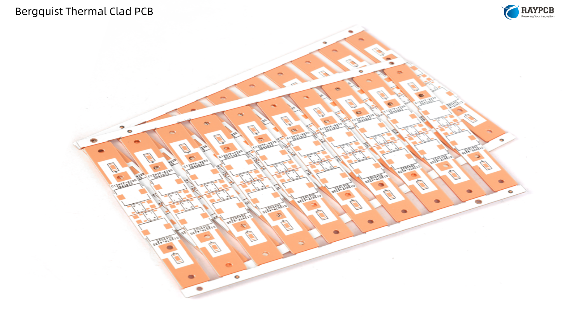
This article gets into the numbers honestly, covers the scenarios where FR-4 still makes sense, and explains why Bergquist Thermal Clad’s metal core architecture routinely outperforms FR-4 in high-power LED, power conversion, motor drive, and automotive applications.
Understanding the Core Problem: Why FR-4 Struggles with Heat
FR-4 is a glass-reinforced epoxy laminate — and that same epoxy matrix that makes it such an effective electrical insulator is precisely what makes it a thermal bottleneck. At its core, FR-4 is an excellent electrical insulator but a poor thermal conductor. Its thermal conductivity is approximately 0.3 W/mK, and the same property making it a great electrical insulator also makes it a thermal barrier.
The problem compounds in the Z-axis, which is the direction heat actually needs to travel in a surface-mount assembly. The thermal conductivity path through the Z-axis is typically as low as 0.29 W/mK. Since heat generated by surface-mount devices must first pass vertically through this Z-axis insulating layer before reaching internal or bottom heat-dissipation planes, effective thermal management strategies must focus on bypassing this vertical bottleneck.
The consequence is predictable: In high-power applications, this can result in temperature rises of 50°C or more above ambient conditions, risking component failure. Additionally, FR-4 has a glass transition temperature of around 130–140°C, beyond which it loses structural integrity, making it unsuitable for extreme heat environments.
Component life typically decreases according to the Arrhenius law as temperature rises — a common empirical rule suggests lifespan approximately halves for every 10°C increase in temperature. That rule of thumb is worth writing on the whiteboard before any high-power material selection discussion begins.
What FR-4 Engineers Do to Compensate — And Why It Has Limits
Strategies for high-temperature FR-4 PCB designs include using thermal vias, incorporating heat sinks, and selecting complementary materials to reduce thermal resistance in FR-4. These workarounds are real and sometimes sufficient:
- Dense thermal via arrays beneath power devices can reduce effective Z-axis resistance
- Heavy copper (2–4 oz) improves in-plane spreading
- External heatsinks with TIM pads redirect heat away from the board
- High-Tg FR-4 variants push the glass transition temperature to 170–180°C
But each workaround adds cost, assembly complexity, and board area. To compensate for its poor heat dissipation, FR-4 often requires external cooling solutions like heat sinks or forced air systems, increasing design complexity and cost. For applications pushing beyond 10–15 watts of power dissipation per square inch, FR-4 often fails to meet thermal requirements, making IMS a better choice.
What Makes Bergquist Thermal Clad Different from FR-4
Bergquist Thermal Clad is an Insulated Metal Substrate (IMS) — a fundamentally different architecture from FR-4. Bergquist’s Thermal Clad dielectric is a thin, thermally conductive layer bonded to an aluminum or copper substrate for heat dissipation. The key to Thermal Clad’s superior performance lies in its dielectric layer. This layer offers electrical isolation with high thermal conductivity and bonds the base metal and circuit foil together. Other manufacturers use standard prepreg as the dielectric layer, but prepreg doesn’t provide the high thermal conductivity and resulting thermal performance required.
The dielectric is a proprietary polymer/ceramic blend that gives Thermal Clad its excellent electrical isolation properties and low thermal impedance. The polymer is chosen for its electrical isolation properties, ability to resist thermal aging and high bond strengths. The ceramic filler enhances thermal conductivity and maintains high dielectric strength. The result is a layer of isolation which can maintain these properties even at 0.003″ (76µm) thickness.
The three-layer build — copper circuit, ceramic-polymer dielectric, metal base — creates a direct and controlled thermal path from solder joint to heatsink that FR-4 simply cannot replicate without significant added hardware.
Bergquist vs FR-4 PCB: Head-to-Head Material Properties
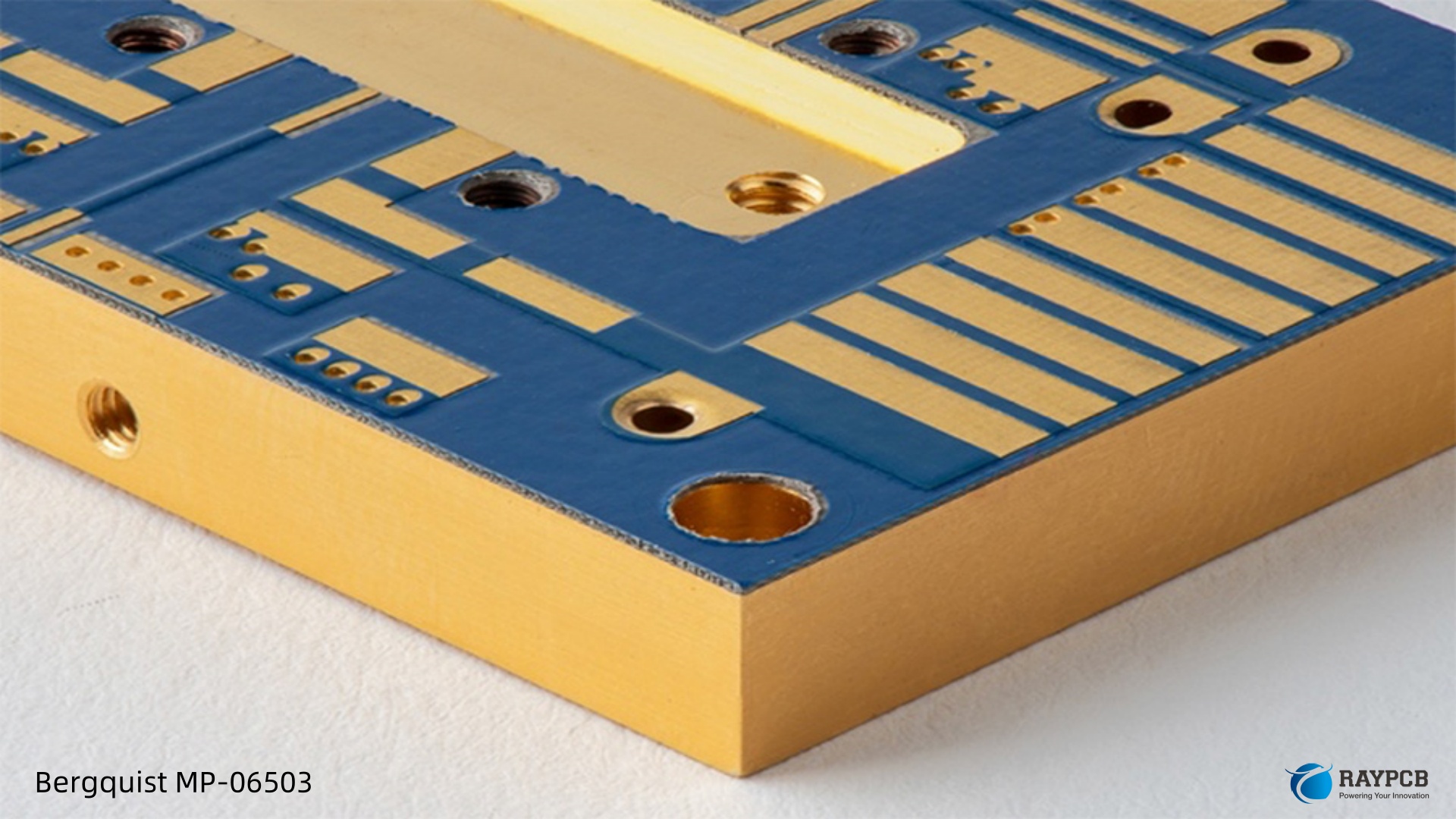
| Property | Standard FR-4 | High-Tg FR-4 | Generic MCPCB | Bergquist MP-06503 | Bergquist HT-04503 | Bergquist HPL-03015 |
| Thermal conductivity (dielectric) | 0.3 W/mK | 0.35–0.4 W/mK | 1.0–2.0 W/mK | 2.4 W/mK | 4.1 W/mK | ~3.0 W/mK |
| Dielectric thickness | 100–200 µm | 100–200 µm | 100–150 µm | 76 µm | 76 µm | 38 µm |
| Base thermal conductor | None (glass-epoxy) | None | Aluminum | Aluminum or Copper | Aluminum or Copper | Aluminum or Copper |
| Glass transition (Tg) | 130–140°C | 170–180°C | ~130°C | 90°C | 150°C | 185°C |
| Max operating temp (UL) | ~130°C | ~150°C | ~130°C | ~130°C | 140°C | 140°C |
| Relative material cost | Low | Low–Medium | Medium | Medium | Medium–High | High |
| External heatsink required? | Usually yes | Usually yes | Sometimes | Rarely | Rarely | Rarely |
| RoHS / Lead-free compatible | Yes | Yes | Varies | Yes | Yes | Yes |
The column that matters most in a thermal-limited design is the top one. At 4.1 W/mK (HT-04503), Bergquist’s dielectric is roughly 14× more thermally conductive than standard FR-4. In a substrate system where the dielectric layer is the dominant thermal resistance, that gap translates directly into cooler components.
The Real-World Thermal Impact: A Practical Comparison
The abstract conductivity numbers only become meaningful when you model them against an actual power stage. Consider a 25W MOSFET in a D2PAK package with a mounting footprint of approximately 1.5 cm². The junction-to-case resistance is 1.0°C/W. You want to know the temperature rise across the substrate dielectric layer alone.
Using standard FR-4 (0.3 W/mK, 150µm thick):
ΔT (dielectric) = (Power × thickness) / (conductivity × area) = (25W × 0.00015m) / (0.3 W/mK × 0.00015 m²) = 83°C across the dielectric layer
Using Bergquist HT-04503 (4.1 W/mK, 76µm thick):
ΔT (dielectric) = (25W × 0.000076m) / (4.1 W/mK × 0.00015 m²) = 3.1°C across the dielectric layer
That 80°C difference doesn’t come from a theoretical model — it comes from the physical heat flow equation. In a high-power LED application, an IMS PCB can reduce the junction temperature of the LEDs by up to 20–30°C compared to FR-4 under the same operating conditions. Lower temperatures translate to better efficiency and a longer lifespan for the components.
Thermal Resistance: The Designer’s True Comparison Metric
Thermal resistance — measured as °C/W or °C·cm²/W — is the number to use when comparing designs, not conductivity alone. FR-4 typically has a thermal resistance of 50–70 °C/W per square inch, much higher than metal-core PCBs at around 10–20 °C/W.
| Substrate | Thermal Resistance (°C·cm²/W) | Notes |
| Standard FR-4 (1.6mm, no vias) | 50–70 | Dominated by low Z-axis conductivity |
| FR-4 with dense thermal via array | 15–25 | Improved but bulky layout penalty |
| Generic MCPCB (1.5 W/mK dielectric) | 1.5–3.0 | Better, but grade-dependent |
| Bergquist MP-06503 | 0.58 | Consistent, well-characterized |
| Bergquist HT-04503 | 0.45 | High-temperature applications |
| Bergquist HPL-03015 | 0.30 | Optimized for LED die-attach |
Where Bergquist Thermal Clad Wins by a Clear Margin
High-Power LED and Solid-State Lighting
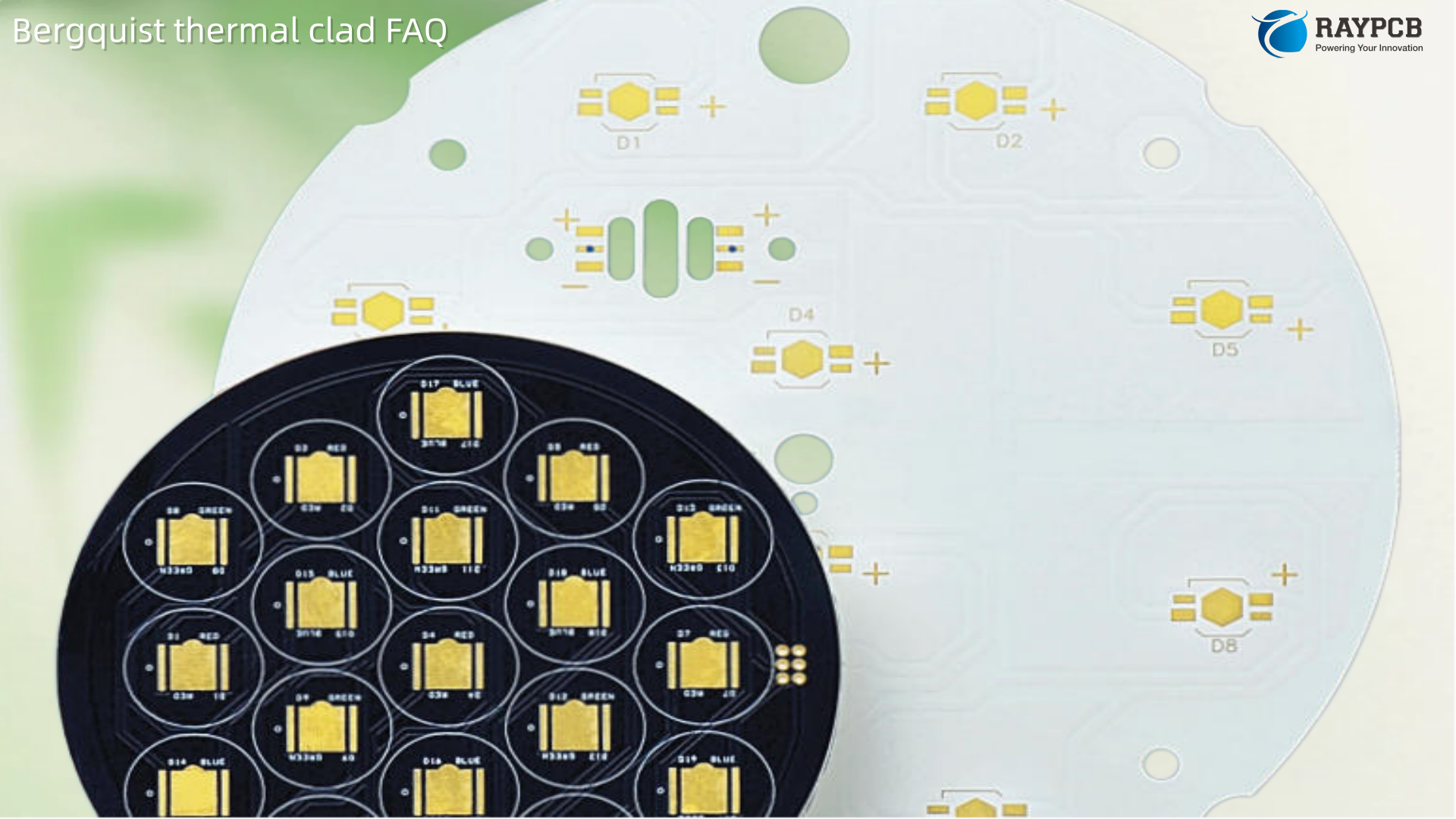
This is where the Bergquist vs FR-4 PCB decision is most clear-cut. LED junction temperature directly controls lumen output, color point, and L70 lifetime (the point where output degrades to 70% of initial). The low thermal impedance of Thermal Clad dielectrics outperforms other PCB materials and offers a cost-effective solution, eliminating additional LEDs for simplified designs.
On a 100W street light array, the delta between FR-4 and Thermal Clad HPL is not just a thermal number — it can mean the difference between an LED array lasting 50,000 hours versus 25,000 hours. Replacing burned-out fixture modules in a city-wide streetlight deployment has real maintenance cost implications that dwarf the material cost premium.
Motor Drives and Variable Frequency Drives
Bergquist’s Thermal Clad PCBs offer superior thermal conductivity, electrical insulation, and environmental compliance, making them ideal for motor drives where heat is a constant challenge. In a VFD, the IGBT or SiC MOSFET switch bank is the dominant heat source, and it cycles between full-on and off at switching frequencies from a few kHz to over 100 kHz. The thermal fatigue on the substrate dielectric under those conditions rules out standard FR-4 on reliability grounds, not just thermal performance grounds.
Automotive Power Electronics
As the automotive industry has shifted toward electric vehicles and advanced driver-assistance systems, these systems demand reliable electronic components that can withstand extreme environments, including fluctuating temperatures and vibrations. Bergquist PCBs handle components like inverters, battery management systems, and electronic control units with ease.
FR-4 is not absent from automotive electronics — most ECU logic boards are FR-4 — but the moment you cross into underhood power electronics with sustained dissipation above 5–10W per square inch, the thermal and temperature-cycling fatigue limits of FR-4 push you toward an IMS solution.
Power Conversion and Solid-State Relays
Due to the size constraints and watt-density requirements in DC-DC conversion, Thermal Clad has become a favored choice. It can be used in almost every form-factor and fabricated in a wide variety of substrate metals, thicknesses, and copper foil weights.
In compact telecom converters or onboard chargers, eliminating the external heatsink assembly that FR-4 requires — mica insulators, spring clips, thermal grease — translates directly to lower BOM cost and fewer assembly steps. With the use of etched traces on the board, interconnects can be removed. This thermal clad helps to replace discrete devices at the board level and allows for increased power density.
Where FR-4 Is Still the Right Call
This is not a one-sided comparison. FR-4 earns its place in the vast majority of PCB designs for a reason.
| Application | Recommended Substrate | Rationale |
| Microcontroller logic boards | FR-4 | Low power dissipation; thermal non-issue |
| Signal processing / DSP boards | FR-4 | No high-power devices |
| RF/Microwave (low-loss req’d) | Arlon PCB or Rogers | FR-4 loss tangent too high; Bergquist not optimized for RF |
| Consumer electronics (<5W) | FR-4 | Cost wins; thermal adequate |
| LED driver logic section | FR-4 | Power stage on Thermal Clad; logic on FR-4 panel attached via pin headers |
| High-power LED array (>10W) | Bergquist Thermal Clad | Thermal Clad HPL or HT wins decisively |
| Motor drive IGBT stage (>20W) | Bergquist Thermal Clad | Thermal + reliability requirements met |
| Automotive power module | Bergquist Thermal Clad | LM or HT depending on cycle count |
| EV inverter (>400V) | Bergquist HT-07006 | Isolation voltage + thermal + reliability |
For RF and microwave applications where loss tangent and dielectric constant stability matter more than thermal conductivity, FR-4 is also not the right call — but neither is Bergquist Thermal Clad. That segment is where Arlon PCB materials (e.g., the AD and CLTE-XT series) are the correct specification. Knowing which of these three material families fits your design is the mark of a well-rounded PCB engineer.
Fabrication and Cost: Honest Trade-offs
Any honest comparison has to acknowledge the cost and process differences between FR-4 and Bergquist Thermal Clad.
Material and Fabrication Cost
Thermal Clad panel stock costs more than FR-4 — sometimes substantially more depending on grade. The HT and HPL series are particularly premium. Beyond material, the fabrication process requires appropriate tooling: carbide drill bits rated for aluminum composite, single-flute CNC router bits to avoid galling, and depth-controlled V-scoring for clean panel singulation.
Design Complexity Trade-offs
| Design Factor | FR-4 | Bergquist Thermal Clad |
| Multilayer routing | Full multilayer available | Primarily single-layer circuit; 2-layer with Bond-Ply |
| Plated through-hole to base metal | Not applicable | Not standard (base is isolated) |
| External heatsink needed? | Usually | Rarely |
| Thermal interface materials in BOM | Often required | Eliminated |
| Pick-and-place assembly | Standard | Standard — same SMT process |
| Via drilling | Standard plated | Non-plated holes in metal; specialized tooling |
| Lead-free solder compatible | Yes | Yes |
Thermal Clad is a cost-effective solution which can eliminate components, allow for simplified designs, smaller devices, and an overall less complicated production process. Cooling with Thermal Clad can eliminate the need for heat sinks, device clips, cooling fans, and other hardware. An automated assembly method will reduce long-term costs.
The fabrication cost premium on Thermal Clad is partially offset by BOM simplification — removing individual mica pads, spring clips, thermal grease application, and heatsink hardware from the assembly process. On high-volume production, that per-unit labor saving can be significant.
Useful Technical Resources for Bergquist vs FR-4 PCB Design
Every engineer comparing these materials at the design stage should have these documents bookmarked:
| Resource | Description | Link |
| Bergquist Thermal Clad Selection Guide | Complete dielectric family comparison, design rules, assembly guidelines | Digi-Key PDF |
| HPL-03015 Datasheet | LED-optimized dielectric, 38µm, thermal resistance 0.30°C·cm²/W | mclpcb.com PDF |
| HT-04503 Datasheet | High temperature dielectric, 4.1 W/mK, 76µm | mclpcb.com PDF |
| HT-07006 Datasheet | 6 mil HT dielectric, 11 kVAC breakdown, 0.71°C·cm²/W | mclpcb.com PDF |
| MP-06503 Datasheet | General-purpose, 2.4 W/mK, 0.58°C·cm²/W | mclpcb.com PDF |
| IPC-2221B | Generic Standard for Printed Board Design | IPC.org |
| IPC-4101 | Specification for Base Materials for Rigid and Multilayer PCBs (covers FR-4) | IPC.org |
| JEDEC JESD51 Series | Thermal measurement standards for semiconductor devices | JEDEC.org |
| Henkel Bergquist Product Page | Current product lineup, distributor links, SDS documents | Henkel Electronics |
5 FAQs: Bergquist Thermal Clad vs FR-4 PCB
Q1: Can I use FR-4 with thermal vias instead of Bergquist Thermal Clad to save cost?
Sometimes yes, but with real limits. Dense thermal via arrays (via-in-pad, filled and capped) can reduce FR-4 thermal resistance meaningfully — bringing it from 50–70 °C·cm²/W down to perhaps 15–25 °C·cm²/W for a well-designed via matrix. If your power dissipation is below ~5W per component and you have layout area to work with, this approach can work and costs less. Above that threshold, or in any design where board size is constrained, Thermal Clad’s consistent 0.30–0.71 °C·cm²/W performance and elimination of external hardware generally wins on total system cost and reliability. The thermal via approach also adds layout complexity and can compromise signal integrity around high-frequency switching nodes.
Q2: Is Bergquist Thermal Clad much harder to fabricate than FR-4?
It requires different tooling and process awareness, but it is not exotic. The aluminum base machines differently from glass-epoxy — carbide drill bits wear faster, routing requires single-flute tools to prevent galling, and V-scoring depth requires tighter control. Standard SMT assembly, LPI solder mask, ENIG or HASL surface finish, and lead-free reflow profiles all transfer directly from FR-4 processes without modification. Any PCB fabricator regularly working with aluminum MCPCB has the right equipment. The main DFM consideration is getting the material spec note right on the drawing: base metal alloy, dielectric grade, copper weight, and any selective dielectric removal requirements.
Q3: Does Bergquist Thermal Clad support multilayer designs like FR-4?
Not in the same way. Standard FR-4 multilayer PCBs with 4, 6, or 8 layers are straightforward. Thermal Clad is primarily a single-circuit-layer substrate. Two-layer configurations are achievable using Bergquist Bond-Ply to laminate a second FR-4 or Thermal Clad circuit to the back of the base metal, but buried vias, blind vias, and standard multilayer constructions are not. For designs that need both high-power thermal management and complex multilayer routing, a hybrid approach is common: power devices on a Thermal Clad section, logic and control circuitry on a conventional FR-4 PCB, interconnected by press-fit pins or flex cable.
Q4: When does it make financial sense to upgrade from FR-4 to Bergquist Thermal Clad?
The crossover point depends on what FR-4 forces you to add to compensate for its thermal limitations. Count the BOM cost of individual TO-220/TO-247 insulators (mica or Kapton), thermal grease or phase-change TIM, heatsink hardware, and assembly labor for torqued fasteners. In a motor drive or power supply with six to twelve power devices, that hardware cost per board can easily reach $3–8 in materials alone, plus the assembly time. Thermal Clad eliminates all of it. The material premium on the board itself is often recovered within the first several hundred units, and the reliability improvement — particularly in warranty cost reduction — frequently makes the financial case compelling even before you reach high volumes.
Q5: Can Bergquist Thermal Clad replace ceramic substrates like DBC?
Thermal Clad can replace large-area ceramic substrates. It can also be used as a mechanically durable support for ceramic spacers or direct bonded copper sub assemblies. The copper circuit layer of Thermal Clad has more current carrying capability than thick-film ceramic technology. For moderate-power applications — say, up to 50–100W single device — the substitution of Thermal Clad for DBC (Direct Bonded Copper on alumina) is viable and typically reduces cost and brittleness risk. At very high power density with bare die mounting and tight thermal budgets, DBC or AMB (Active Metal Brazed) ceramics on aluminum nitride maintain an edge in bulk thermal conductivity. Thermal Clad sits between FR-4 and DBC in both performance and cost — which happens to be exactly where most industrial and automotive power electronics designs live.
Final Thoughts on Bergquist vs FR-4 PCB
The Bergquist vs FR-4 PCB choice is not actually complicated once you run the thermal numbers. FR-4 is a superb material for the overwhelming majority of electronic designs where power dissipation is moderate and thermal management can be handled with copper planes and selective use of heatsinks. The moment a design needs to move more than roughly 10W per square inch through the substrate consistently, FR-4’s 0.3 W/mK Z-axis conductivity becomes the design’s weak link.
Bergquist Thermal Clad’s proprietary ceramic-polymer dielectric eliminates that weak link. The result — direct junction-to-metal-base thermal conduction, no added TIM hardware, consistent and well-characterized thermal resistance values — is precisely why it has been the benchmark MCPCB dielectric for LED, motor drive, power conversion, and automotive power electronics for decades.
Make the material decision early, run the thermal resistance stack calculation honestly, and choose the dielectric grade (HPL, HT, MP, or LM) that fits your voltage isolation and thermal budget. That order of operations will keep your design out of warranty returns and off the teardown bench.