
RAYPCB · RF ENGINEERING
RF Circuit Design Workflow: Architecture to PCB Handoff
RF circuit design is a sequence of decisions about signals, interfaces and verification. Before drawing a PCB, define what the circuit must receive or transmit, the conditions under which it operates, and how each requirement will be measured. A useful workflow turns those requirements into a signal chain, assigns budgets to its stages, and carries the assumptions into layout, prototype testing and production documentation.
This page addresses system and circuit planning. It does not imply that an online worksheet can design a radio chip or approve a complete RF product. Its purpose is to help engineers and purchasers describe a build clearly enough that circuit work, PCB fabrication and assembly are not confused in the quotation.
Start with an operating scenario
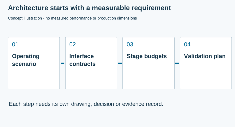
Write down the wanted signal, operating frequency interval, bandwidth, operating modes and expected interferers. Distinguish an absolute maximum condition from a normal operating condition and from a performance target. A receiver that survives a strong signal may still be unable to receive a weak wanted signal in its presence.
For a transmitter, identify the required output reference plane, modulation, duty cycle and load conditions. For a receiver, identify sensitivity or other receiver-performance requirements together with bandwidth, modulation and the test method. The same headline number can describe quite different tests. Avoid building a component shortlist around an unspecified sensitivity or power claim.
Environmental and mechanical conditions belong here too. Supply range, temperature, housing, connector access and antenna installation may affect architecture choices. Capture which conditions must be met simultaneously. It is often easier to resolve an incompatible requirement before selecting parts than after routing the board.
Create an interface contract for every block
| Interface | Information to assign | Why it matters |
|---|---|---|
| RF input or output | Band, reference impedance, level and reference plane | Enables meaningful gain, loss and matching comparisons |
| Bias supply | Voltage range, current, sequencing and noise considerations | Connects power design to RF operating conditions |
| Control | Logic levels, timing and states during measurement | Prevents comparing different operating modes |
| Clock or local oscillator | Frequency plan and relevant spectral requirements | Exposes potential interference and conversion products |
| Mechanical boundary | Connector, mounting and enclosure relationship | Keeps test and installed configurations comparable |
Use part-specific documentation for interfaces that are not generic matched ports. A differential chip connection may include bias or a particular complex load. Inserting a nominal 50-ohm component into that interface without the required network is not a complete design. Record the source of each interface assumption so another engineer can review it.
Review the signal chain before optimizing components
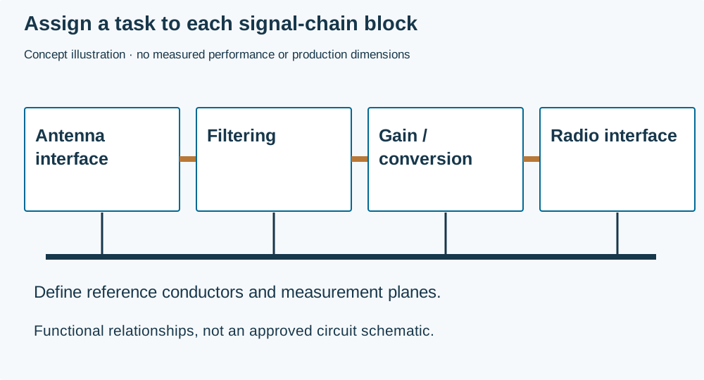
Separate gain, loss, noise, linearity, filtering and matching responsibilities. Their order matters. Loss ahead of a receiver's first active stage has a different system implication from the same loss later in the chain. A filter can protect a stage from an interferer while adding insertion loss. A high-gain stage can improve one budget and reduce available headroom elsewhere.
Do not add decibel quantities indiscriminately. Gain and insertion loss can be combined under stated matched, linear conditions, whereas noise factors and nonlinear distortion require their appropriate models. Cascaded calculations are useful only when the component data describe compatible operating points and impedances. A small-signal model does not prove behavior near compression.
Use the component vendor's evaluation data as a starting reference and identify where your circuit differs. The Mini-Circuits filter catalogue distinguishes filter families and links to device-specific information. For an actual selection, read the chosen part's conditions rather than treating a family headline as a guarantee for every device.
Build a review brief from the requirements
The worksheet runs locally in your browser with JavaScript. You can contact RAYPCB directly without completing it.
RF requirements brief
The requirements worksheet records a band, signal-chain purpose, interfaces and the test owner. It highlights incomplete decisions and creates a text brief for discussion. It deliberately does not synthesize a matching network, rank semiconductor suppliers or return a design-approved result. That boundary keeps the output useful to both engineering and purchasing.
An early-stage example might describe a receiver front end with a selected radio module but an unresolved filter and antenna installation. The useful output is an interface record stating what is known, the expected external signal conditions, and who will evaluate the missing elements. Entering invented filter values to make the form complete would make the next review less reliable.
Keep simulation levels separate
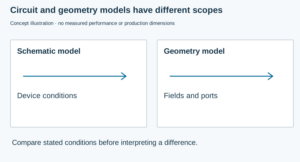
Circuit simulation can evaluate a schematic with defined device models. Electromagnetic simulation can examine distributed geometry such as a line, launch, filter layout or antenna. A system model can explore the behavior of multiple stages under its assumptions. These models can inform one another, but none automatically contains the detail omitted from its inputs.
Record model provenance, version, operating point and frequency coverage. Identify any ideal components used for early exploration. When replacing an ideal component with a real package, include the relevant parasitics and mounting structure. A schematic that converges successfully is not necessarily a manufacturable or stable circuit.
Before comparing models, align the ports and reference planes. Check whether a vendor data file includes a fixture, package or evaluation-board trace. Adding the same structure again in another model can double-count it; omitting it can make the prediction optimistic. Preserve the original data and document any de-embedding or conversion.
Transfer the architecture into a board-level plan
Identify the RF paths that need controlled geometry and the components whose placement follows a reference layout. Allocate reference planes, supply routing, shielding access and measurement interfaces before dense placement closes off options. A clean block diagram still needs a physical implementation that preserves those interfaces.
Use RF PCB design for that next stage. Keep the circuit requirements linked to the layout constraints: a band-limited filter may need a particular land pattern, a connector may need a specific launch, and an antenna may need an unobstructed installation region. Those are engineering requirements, not optional cosmetic details.
For noise problems that involve other subsystems, record the source and coupling path instead of adding shielding everywhere. A converter's operating mode, a clock harmonic or an external cable can change the interference environment. The RF EMC layout guide provides a focused path for that review.
Plan tests before ordering the prototype
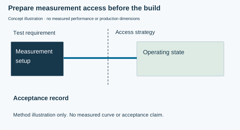
List the result, instrument or fixture, operating state, calibration plane and acceptance criterion for each requirement. Separate diagnostic measurements from acceptance measurements. A near-field scan may help locate a source but is not automatically the specified radiated-emissions test. A power reading at one connector does not characterize the entire antenna system.
Decide how the prototype exposes the needed nodes without introducing unacceptable RF branches. If shield removal, alternate component populations or a special fixture are required, identify them in the assembly plan. Define which tests occur before the product is closed and which require the final enclosure.
Save raw measurement files with the board revision, BOM population and firmware version. A screenshot alone may omit sweep settings or calibration details needed to reproduce a result. Where a result is processed, retain the script or settings and explain what was removed or normalized.
Use a staged release rather than one vague approval
An architecture review can confirm that requirements and interfaces are coherent. A layout review can confirm that the intended physical construction is specified. Prototype validation can assess the built circuit against defined requirements. A manufacturing review can confirm the proposed production and inspection route. These are related decisions with different evidence.
For example, a prototype may meet conducted RF requirements while its enclosure integration remains open. Record that state accurately. The board can be suitable for another engineering build without being ready for unrestricted production. Clear status prevents a procurement team from interpreting a successful single test as approval of the complete product.
Quote the work that is actually required
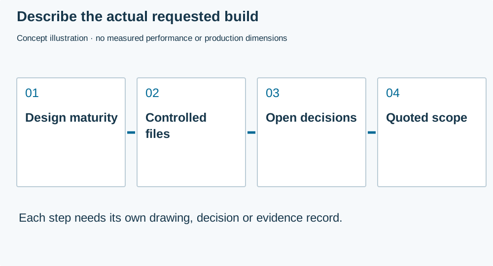
State whether the request is for bare boards, component procurement, PCB assembly or a build with customer-defined testing. Attach the available schematic, BOM, PCB outputs and test instructions, and identify any design work still owned by your team. Do not assume a fabrication order includes circuit redesign or RF certification.
Use RF PCB manufacturing for the RF construction and PCB Manufacturing for general fabrication scope. A project enquiry can include the worksheet as a manually attached discussion brief. The contact form does not automatically receive the local worksheet entries.
Common planning questions
Must every block use the same impedance?
No. Interfaces must be compatible with their actual devices and networks. A system may contain matched external ports and internal interfaces with different loads. Define the transformation and the reference plane where each specification applies instead of imposing one number everywhere.
Can a bill of materials establish that a circuit will work?
No. A BOM identifies parts, but not all operating conditions, interconnections, layout effects or validation evidence. Pair it with the schematic, construction data, population options and test plan. Approved alternatives need an engineering review appropriate to their role in the signal chain.
What is the most useful first enquiry attachment?
A concise requirement and interface brief is useful when the layout is not ready. When manufacturing files exist, provide the controlled release and identify unresolved items separately. A clear scope and revision are more actionable than an unlabelled collection of screenshots and draft files.
Engineering guide · Content prepared 1 October 2026. Diagram and example labels distinguish explanations from product or test evidence.