
RAYPCB · Isola materials and manufacturing
Isola IS400 PCB: assembly exposure and material selection
Explore IS400 material data and an explicit time-temperature profile, then prepare the construction and evidence for manufacturing review.
Share your current requirements and open questions. Tool use is optional.
What is an Isola IS400 PCB?
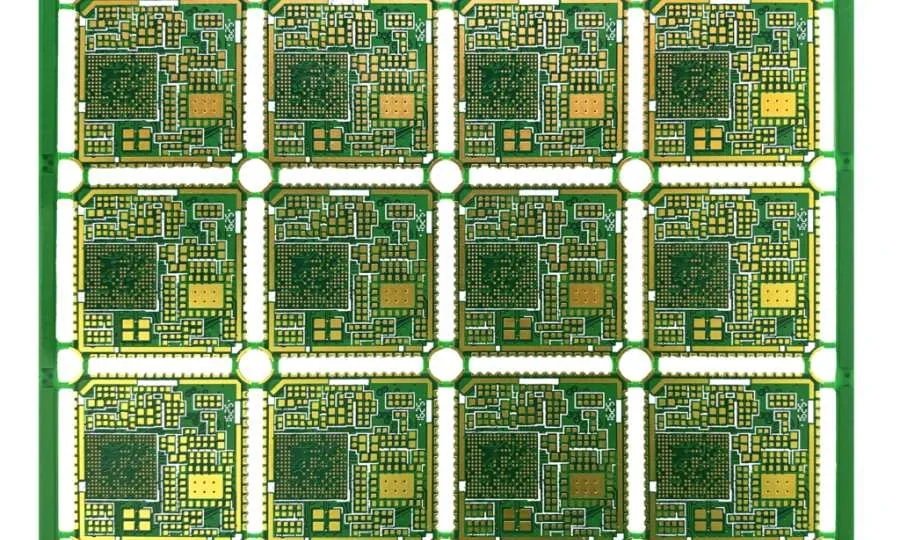
An Isola IS400 PCB uses the specified IS400 laminate and prepreg system in a released circuit-board construction. Material selection should be connected to the board's fabrication, assembly and service requirements. A Tg value helps describe a resin transition; it does not, by itself, tell you how many soldering passes a board can withstand or what temperature the finished product may operate at.
The official IS400 product data lists typical Tg of 150°C by DSC and Td of 330°C by TGA at 5% mass loss. The electrical table reports Dk 3.90 and Df 0.022 at 500 MHz using IPC-TM-650 2.5.5.9. Preserve that frequency: these entries should not be presented as a 2 GHz comparison against another grade.
| Material reference | Typical supplier value | Important distinction |
|---|---|---|
| Tg by DSC | 150°C | Transition measurement, not a soldering maximum |
| Td at 5% mass loss | 330°C | Decomposition test, not a usable service rating |
| Dk / Df at 500 MHz | 3.90 / 0.022 | Frequency and method must stay with the values |
| Material requirement | IS400 core/prepreg system | Must match the approved construction |
This page focuses on describing thermal exposure and evidence. For a broader material decision, use the Isola PCB family guide. If the design starts from a generic Tg150 requirement, clarify its measurement method and actual thermal mission before selecting a named material.
Separate four different temperature questions
Material transition, laboratory delamination testing, assembly exposure and service temperature answer different questions. Confusing them can produce a misleading specification even when each quoted number is accurate. A useful manufacturing inquiry describes the actual board and the process it will experience, with the required acceptance evidence.
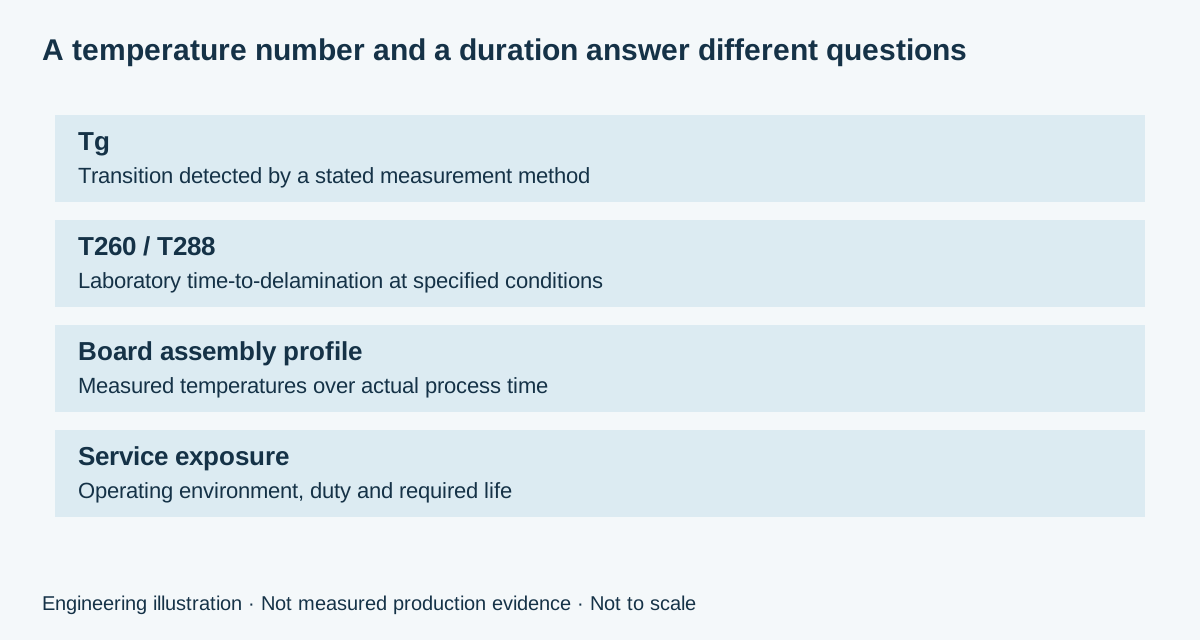
| Question | Relevant information | What it does not establish alone |
|---|---|---|
| Where does the resin transition occur? | Tg with measurement method | Continuous operating temperature |
| How does a test specimen behave at a fixed temperature? | T260/T288 with test conditions | Allowable number of assembly passes |
| What happens during soldering? | Measured board time-temperature profile | Long-term product reliability |
| What happens in use? | Environment, duty, constraints and lifetime | Automatic material approval from a Tg label |
Crossing Tg does not mean immediate failure. It means aspects of the material response change, which can influence a constrained board structure. Whether a construction is suitable depends on more than the peak temperature: geometry, moisture, copper, holes, exposure history and the applicable qualification plan all matter.
Explore an assumed board-temperature profile
The tool models a linear heating ramp, a flat peak hold and a linear cooling ramp. Enter start, peak and end temperatures, the duration of each segment, a material reference threshold and the liquidus temperature relevant to your solder example. It reports total duration, ramp rates and time above each threshold separately.
RAYPCB ENGINEERING
Isola Material EngineeringIsola IS400 PCB Engineering Planner
Loading Isola IS400 PCB Engineering Planner…
For the illustrative profile, the board starts at 25°C, heats to 235°C in 120 seconds, holds for 30 seconds and returns to 25°C in another 120 seconds. Total duration is 270 seconds. The calculated time above a 150°C reference is about 127.1 seconds. Above an independently entered 217°C liquidus, it is about 50.6 seconds.
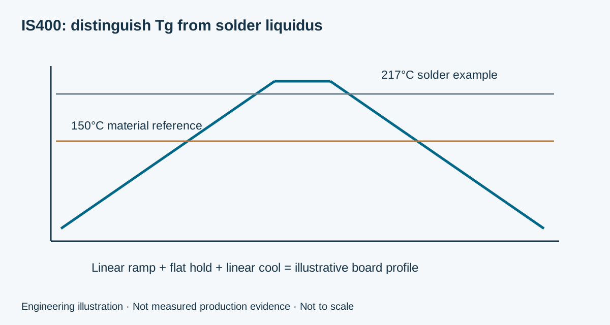
These are mathematical results for an assumed shape. The 217°C value is an example input, not a universal solder requirement. Real profiles may include soak regions, multiple slopes and different temperatures at different positions on a populated board. Measure the process and use the requirements for the actual solder, components and construction.
Do not use this result as an oven recipe or subtract its time above Tg from a datasheet T260/T288 result. The thresholds, exposure conditions and specimens are different. The calculator deliberately returns no pass/fail label and no remaining-life estimate. Its purpose is to make the assumptions visible before engineering review.
Record the full fabrication and assembly history
List the processes the board is expected to experience: relevant lamination stages, assembly passes, selective soldering, local heating and possible rework. Separate known conditions from assumptions. A design described only as “lead-free assembly” can conceal different process histories and therefore different engineering questions.
For a double-sided assembly, identify which side is processed first and how the second pass affects the complete board. If heavy components, heat sinks or large copper areas produce thermal differences, include those concerns in the process review. An assumed uniform temperature curve cannot represent every local region of a populated assembly.
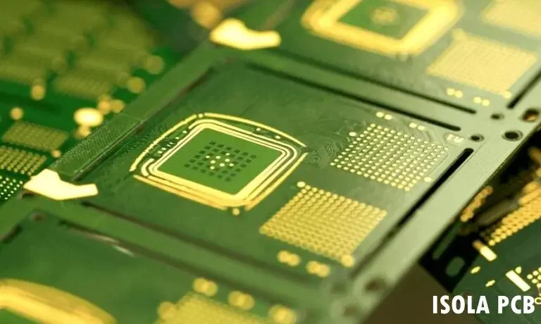
Use the PCB assembly process guide to organize the manufacturing sequence. The material decision belongs within that sequence. Changing board thickness, copper distribution or components may require a new profile assessment even when the laminate name stays the same.
Connect thermal exposure to the actual board
Specify the core and prepreg system, glass style, resin content, proposed dielectric thickness and copper requirement. Include the hole construction and finished dimensions. Expansion and mechanical constraint occur in the completed board, so a datasheet alone cannot describe the stress history of every plated interconnection or mounted component.
If the board requires controlled impedance, define the layer structure and relevant electrical data separately. IS400's cited 500 MHz table entries cannot simply be substituted into a comparison at another frequency. Use a suitable construction-specific model and agree any trace adjustment or coupon requirement with fabrication engineering.
For an existing product, compare the proposed build with the approved construction. Material substitutions, changed prepreg combinations or altered copper can affect more than procurement. Record the change and identify what evidence or customer approval is needed. A supplier's proposed alternative should be reviewed against the original design requirements, not only a nominal Tg category.
Ask for evidence at the correct level
Material documentation, bare-board inspection, assembly process records and product qualification have different scopes. A material test or recognition does not certify the whole PCB assembly or its final equipment. If an application names a sector-specific requirement, identify the applicable document, revision, construction scope and responsible approval process.
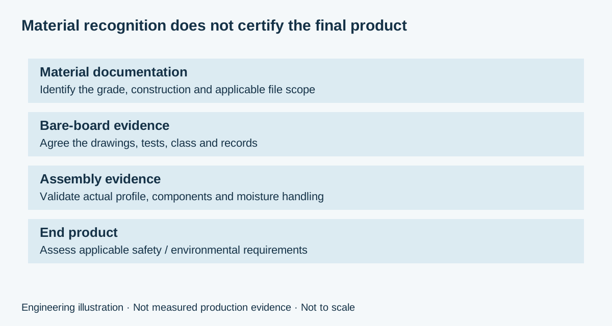
A useful request links each concern to an observable record. Material identity may call for traceability. A hole-geometry concern may call for a specified inspection or microsection. An assembly concern may require measured profiling and an agreed inspection plan. Long-term performance needs the relevant product or construction qualification, rather than a generic claim that “high Tg” guarantees reliability.
The PCB quality-control page provides a route into the manufacturing evidence discussion. Select the records that serve the design's risk and acceptance requirements. Agree their scope before quotation so that documentation and additional testing are included consistently in competing proposals.
Treat storage and moisture as process inputs
Moisture condition and handling history should be considered with thermal exposure. Ask for packaging, storage and handling instructions suitable for the actual construction and finish. A universal baking instruction is not appropriate for every bare board, assembled component or process history, and this page does not prescribe one.
Identify when the material or board will be exposed between stages and how deviations will be handled. If storage conditions or elapsed time differ from the approved process, have the responsible manufacturing team review the condition. A measured temperature profile cannot compensate for missing information about material identity or handling.
For repeat orders, retain the approved drawing, material construction and process-related requirements together. Avoid allowing a purchasing description, fabrication drawing and assembly instruction to drift into different versions of the product. Clear revision control makes technical discussions and quotations easier to compare.
Build an IS400 inquiry around a defined scope
The manufacturing cost depends on the named material construction, quantity, panel use, layer count, drilling, copper, finish and evidence requirements. Additional thermal or first-article work should be identified explicitly. A material datasheet does not establish stock availability, lead time or the price of your specific construction.
RAYPCB ENGINEERING
Isola Material EngineeringIsola IS400 PCB Budget Brief
Loading Isola IS400 PCB Budget Brief…
Leave costs blank to create a technical brief. If a supplier quotation or internal allowance is available, record its date and scope before entering unit, setup and verification amounts. The calculator totals the entered costs; it does not generate a current market estimate or infer a price from the thermal profile.
When requesting alternatives, keep board requirements and evidence scope comparable. Identify whether an alternative requires a new construction approval or assembly assessment. For a direct review, send the drawing revision, proposed stackup, quantities and known thermal exposures through Contact. There is no requirement to finish a calculator before making an inquiry.
IS400 material and process questions
Does Tg150 mean a board cannot be soldered above 150°C?
No. Tg describes a measured material transition. Soldering suitability must be evaluated using the actual construction, exposure, handling and qualification requirements. It is not decided by comparing the process peak with Tg alone.
Is time above Tg a board lifetime allowance?
No. The tool reports a duration in an assumed profile. It does not model damage accumulation, fatigue or service life. Laboratory time-to-delamination values also cannot be converted directly into a remaining number of reflow cycles.
Can this tool choose an oven setting?
No. Oven settings and actual board temperatures are different. The tool describes an assumed board-temperature shape. A process engineer must measure and establish an appropriate profile for the real assembly and its material requirements.
Can I compare the cited Df directly with a 2 GHz number?
Not as a like-for-like comparison. The cited IS400 values are at 500 MHz with a stated method. Obtain suitable frequency- and construction-specific information before drawing a material-selection conclusion.
Request IS400 PCB manufacturing review
Send the named laminate and prepreg, drawing revision, stackup, quantities and required evidence. Identify open material, construction or qualification questions so engineering can prepare a useful manufacturing proposal.
Attach a downloaded tool brief manually. Contact does not automatically receive these inputs. References reviewed September 2026. Illustrations use planning examples; photographs do not establish prices, delivery times or project-specific acceptance.