
RAYPCB · RF materials & manufacturing
TF-1/2 PTFE laminate: identity and RF comparison
Identify the Wangling TF construction before comparing it with a named Rogers ceramic-PTFE grade. Use the explanations, source documents and interactive calculations to make the next engineering decision with clear assumptions.
Bring your band, stackup, quantity and acceptance requirements. Preliminary files are welcome for review.
Start with the engineering decision
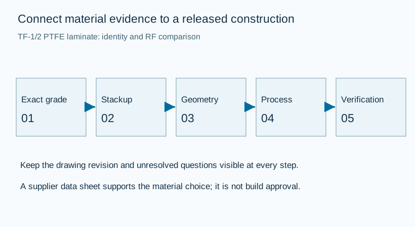
| Planning item | Working definition |
|---|---|
| Primary task | Identify the Wangling TF construction before comparing it with a named Rogers ceramic-PTFE grade |
| Model boundary | Identify the construction, units, method and acceptance question before calculation. |
| Useful output | A documented decision, a reproducible model or a complete fabrication brief. |
| Next engineering step | Rogers PCB distributor: Specification & Quotation |
TF-1/2 is a Wangling material-family designation, not a Rogers product name. The slash must not be silently converted into a presumed TF-12 grade. Identify the exact offered TF construction from the supplier record before comparing it with RT/duroid 6006 or 6010.2LM. This page retains its established URL while keeping the manufacturers and material identities separate.
Material identity brief
Use explicit construction inputs. Results can be downloaded or opened as an email draft; the tool does not upload project information.
Worked planning example
A complete identity record might contain a grade and suffix, a dated supplier document, the selected thickness and foil, and a statement that any substitution needs approval. Unknown Dk and loss values should remain open until that construction is identified. A blank field is more useful than an unsupported default.
Use the result to inspect scale and sensitivity. Preserve the input units and assumptions in the downloaded brief, then use the actual finished geometry and appropriate solver or measurement method for release.
RAYPCB ENGINEERING
Rogers EngineeringRogers Engineering Workbench
Loading Rogers Engineering Workbench…
Recovering a legacy material without inventing a replacement
Older circuit drawings often preserve a trade name after the product range, documentation or supply route has changed. The correct first step is to identify the exact material that the design used. Record the complete designation, suffix, datasheet date, thickness and foil construction. A current web page with a similar name is not enough to establish equivalence. Neither is a product photograph, because visually similar RF boards can use very different dielectric systems.
Separate three questions: what was originally specified, what can be sourced now, and what a replacement would need to demonstrate. An archived document can answer the first question while saying little about present availability. A supplier quotation can answer availability for a particular construction, but it does not automatically qualify the material for an old design. Engineering acceptance needs a comparison of the relevant properties and the finished circuit behavior.
For an RF replacement, compare more than nominal dielectric constant. Include the appropriate design model, loss behavior over the operating band, thickness tolerance, copper profile, temperature dependence and mechanical construction. Review bond compatibility, machining and assembly exposure as well. If the old model is unavailable, plan how to correlate a representative coupon or prototype rather than selecting a new value merely because it produces a familiar trace width.
Maintain a clear distinction between a safety information sheet, an electrical datasheet and a fabrication guide. The safety sheet helps identify handling considerations and the product name; it is not a complete electrical design specification. An old test report may describe one material lot or sample configuration. Preserve the date and test context when using that record, especially if the new build changes thickness, foil or processing.
The material-identification tool creates a structured request without filling unknown engineering inputs with plausible numbers. Send the original drawing and any retained laminate records with the enquiry. Mark substitutions as requiring approval until the design authority has reviewed them. A controlled qualification build can then resolve the open questions in a visible sequence: identity, construction, geometry, fabrication, measurement and release.
How to turn a datasheet into usable design inputs
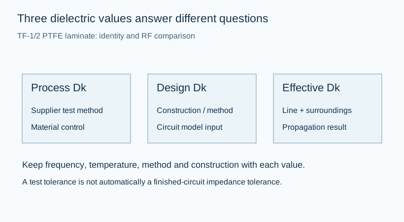
Read the property, the test method and the condition as one record. A dielectric constant without frequency, temperature or method can be ambiguous. A typical value is also different from a purchasing tolerance. The table on this page separates supplier process Dk from design Dk so that an engineer does not accidentally transfer a quality-control measurement into a circuit model with a different definition.
Effective permittivity belongs to the transmission-line structure. For an air-covered microstrip, some of the field occupies air and some occupies the substrate. For a homogeneous centered stripline, the field arrangement is different. Neither quantity should be casually relabeled as the material's process Dk. The same laminate can therefore appear in two correct calculations with different effective permittivities because the geometries differ.
Preserve document revisions when recording values. A supplier may publish a design reference that depends on thickness, copper configuration, frequency range or a particular extraction method. The presence of a newer document does not mean that an old approved circuit should be changed without review. Compare the relevant construction and determine whether the design model, procurement specification or acceptance record needs revision.
A useful material comparison holds the circuit task constant. Begin with the same electrical length or board geometry, then state which variable is allowed to change. Comparing one material at a different thickness, foil type and fixture can obscure the reason for a performance difference. Keep the comparison small enough to answer a defined question, such as trace-width change at equal impedance or dielectric attenuation under an explicitly constant-Df assumption.
When the material is selected, carry the chosen construction into the fabrication drawing. Specify the supplier grade, core thickness, copper type, finish, bond layers and critical RF dimensions. Leave unresolved items visibly open for engineering review. This page is the data interpretation step; the linked manufacturing page carries the selected material into a quote-ready board description.
From a nominal line to a toleranced RF layout
Establish the local cross-section before choosing a trace width. Record the dielectric height, material model, copper thickness and reference-plane arrangement. A total board thickness is not a valid substitute for the distance to the reference plane unless the structure is truly a two-layer core with that definition. For stripline, check whether the trace is centered and whether the dielectric is homogeneous on both sides.
Use a preliminary calculation to estimate scale, then evaluate the actual construction in a suitable solver. The ideal line model provides a reproducible starting point, but it does not include solder mask, trapezoidal etch shape, conductor roughness, dispersion or a three-dimensional connector launch. A calculator output with many decimal places is still only as useful as the assumptions that generated it.
Translate manufacturing variation into circuit questions. A width tolerance, dielectric-height tolerance and Dk variation do not necessarily combine as a single worst-case impedance number for every circuit. Establish which variables can move together and which are independently controlled. For a filter, sensitivity of resonator length and coupling gap may be more useful than one line-impedance estimate. For an array, phase tracking across paths can matter more than a nominal delay value.
Keep a continuous and intentional return structure. Slots, voids, antipads and layer changes can alter the fields even when the trace width remains constant. Where a signal transitions to another layer, review the return connection and launch geometry. Where a metal enclosure or shield is close to the line, include it in the final electromagnetic model. The schematic net name does not describe those physical boundaries.
Release a drawing that links the electrical model to measurable construction. Identify critical dimensions, stackup revision, allowed substitutions and the test method. If a prototype leads to a geometry adjustment, record the reason and the revised model rather than allowing the change to remain an undocumented fabrication compensation. That record makes later procurement and repeat production substantially easier to compare.
Cost planning and a direct RFQ route
Where the cost changes, and which savings are real
For a small RF order, setup, procurement and test preparation may matter as much as the area of laminate. A panel that holds more circuits spreads some shared effort across more boards, but only if the orientation, tooling and coupon requirements permit that layout. The budget tool uses an explicit rectangular nesting model so that its area assumption can be inspected. It does not assume every visible square millimeter of a panel becomes a delivered board.
Copper foil, core thickness and bonding system are part of the purchased construction. A quotation based on a different thickness or foil is not a clean price comparison, even when the headline material name matches. Ask whether the offered material is standard for the supplier's available construction and whether minimum purchases, special handling or qualification work affect the lot. Availability and lead time must be confirmed for the actual order rather than inferred from a web page.
Complexity can move cost in several directions. A hybrid stack may reduce the amount of premium RF laminate while adding press planning and interface review. Metal backing can improve a thermal path while adding bonding and machining requirements. Extra coupons or RF fixtures can reduce uncertainty but add material, setup and measurement work. Compare the complete project scope instead of ranking designs by laminate price alone.
The optional numerical budget uses cost allowances entered by the visitor. It contains no calibrated RAYPCB tariff and does not claim current market pricing. The model combines the costed panels, one-time setup, batch testing and per-board processing; assembly is included only when selected and entered. Shipping, taxes, process yield loss and unentered qualification are excluded. A zero value means already included or deliberately zero, not unknown.
When geometry, quantity or supply scope changes, revisit the allowances. A per-board processing cost from one batch may not apply to another. The tool clears old allowances on those changes to avoid presenting a stale total. Hybrid, metal-backed, unresolved and more complex multilayer constructions go to engineering quotation. The downloaded brief remains useful because it carries the requirements and assumptions even when a numerical price would be misleading.
RAYPCB ENGINEERING
Rogers EngineeringRogers Fabrication Budget & RFQ
Loading Rogers Fabrication Budget & RFQ…
Prefer to send files now? Contact the RAYPCB team with the requested material, construction and quantity. An exact quotation is based on the agreed scope.
Verify the construction that matters to the product
A measurement plan that answers the design question
Begin with what the prototype must establish. Is the question electrical continuity, line impedance, insertion loss, phase balance, resonant frequency, thermal behavior or mechanical fit? These are different tests and they may require different coupons, fixtures and acceptance limits. A test label without the represented structure and measurement method leaves room for two parties to interpret the result differently.
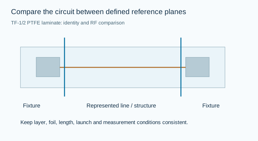
For RF measurements, define the reference planes and account for the launch or fixture. A raw network-analyzer trace can include connectors and transitions that are not part of the material comparison. De-embedding or a representative reference structure may be needed, depending on the question. Record calibration, frequency span, temperature and the circuit revision with the result. This makes later comparisons more informative than a single unqualified pass statement.
Investigate a disagreement between the model and the board in a controlled sequence. Check the finished conductor dimensions, dielectric height, material construction and measurement setup before changing the Dk to force a fit. The model may omit a nearby cover, a return-path discontinuity or a loss mechanism. Equally, the test fixture may represent a different structure from the intended coupon. Identifying the cause protects the next build from an accidental compensation.
Keep the accepted construction and records together. A successful prototype supports the tested revision under its stated conditions. Changes to material, foil, bond system, geometry, assembly exposure or test scope deserve review before a repeat order is treated as equivalent. The project does not need every possible test; it needs the evidence that resolves its actual risks and acceptance requirements.
RAYPCB ENGINEERING
Rogers EngineeringRogers Construction Explorer
Loading Rogers Construction Explorer…
Questions before the next design or purchase decision
What should this page help me decide?
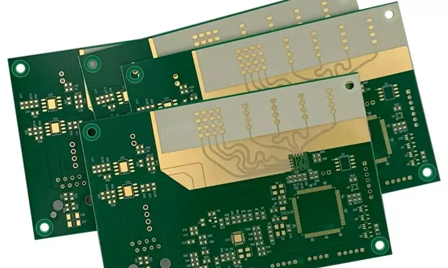
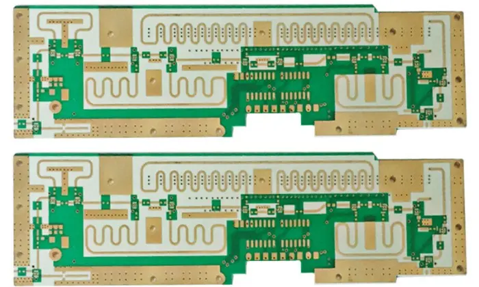
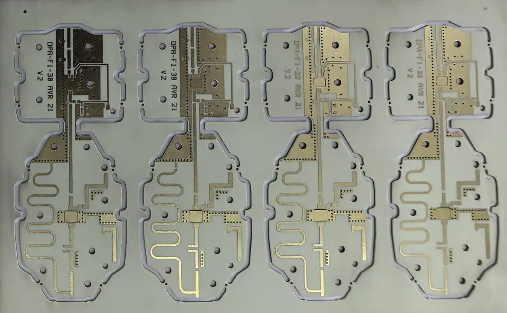
Identify the Wangling TF construction before comparing it with a named Rogers ceramic-PTFE grade. Start with the named construction and the relevant engineering requirement. The photographs show physical circuit examples, while the original-source links and explicit model assumptions support the technical review.
Does the design tool approve this PCB for manufacture?
No. It calculates the stated preliminary model or organizes a construction brief. Finished copper, transitions, mixed dielectrics, assembly interfaces and process limits may require a more complete review. The downloaded result preserves assumptions so engineering can evaluate the same inputs.
Can I obtain a price without completing the tool?
Yes. Use the direct Contact or email route with your drawing, quantity and construction requirements. The optional budget uses your entered allowances and an explicit panel model; it is not a calibrated RAYPCB tariff. Complex constructions need a file-based quotation.
What should I send with an enquiry?
Include the exact material designation, fabrication artwork, drill data, outline, proposed stackup, copper, finish and quantity. Add the relevant impedance, RF, thermal or mechanical acceptance requirements. If assembly is included, provide the BOM, placement data and test expectations.
Continue with the right engineering task
Original technical references
Supplier documents support material identity, properties and methods. They do not establish current stock or qualify an unspecified finished board. Check the exact grade, construction and document revision for your order.