
RAYPCB / RF MATERIALS & FABRICATION
Taconic TSM-DS3M PCB Material: Properties & Design
DS3M routing and phase planning at nominal Dk 2.94. Use the source context, engineering checks and project tools below to turn the material name into a usable fabrication specification.
Request a Taconic PCB quote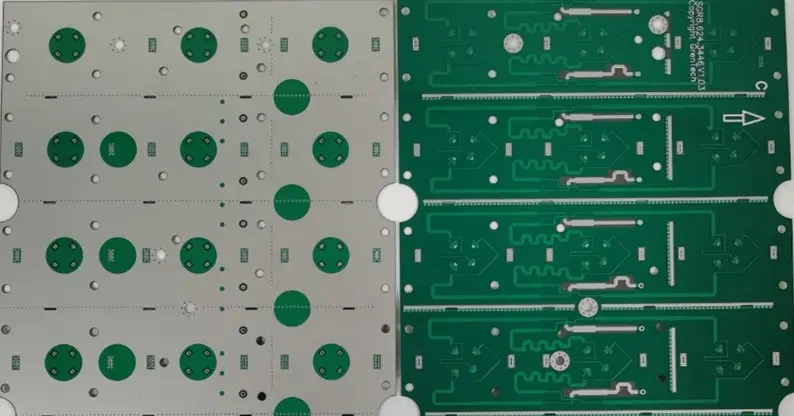
What to specify for TSM-DS3M
Taconic TSM-DS3M is covered here as a named RF material. DS3M is not a 3.00-Dk DS3 core. A geometry transfer between them needs recalculation.
| Field | Specification context |
|---|---|
| Material identity | TSM-DS3M |
| Reference Dk | 2.94 |
| Reference Df | 0.0014 |
| Test context | Dk/Df: current AGC guide at 10 GHz |
| Thermal conductivity | 0.65 W/m·K; see specimen/test condition |
| Supply status | Confirm current grade, thickness, foil and order quantity; no stock promise |
Do not miss: DS3M is not a 3.00-Dk DS3 core. A geometry transfer between them needs recalculation.
Reference trail: Supplier material reference · Grade data sheet · Processing guide. Numerical values are typical material references, not purchase acceptance limits, live stock or guaranteed fabricated performance.
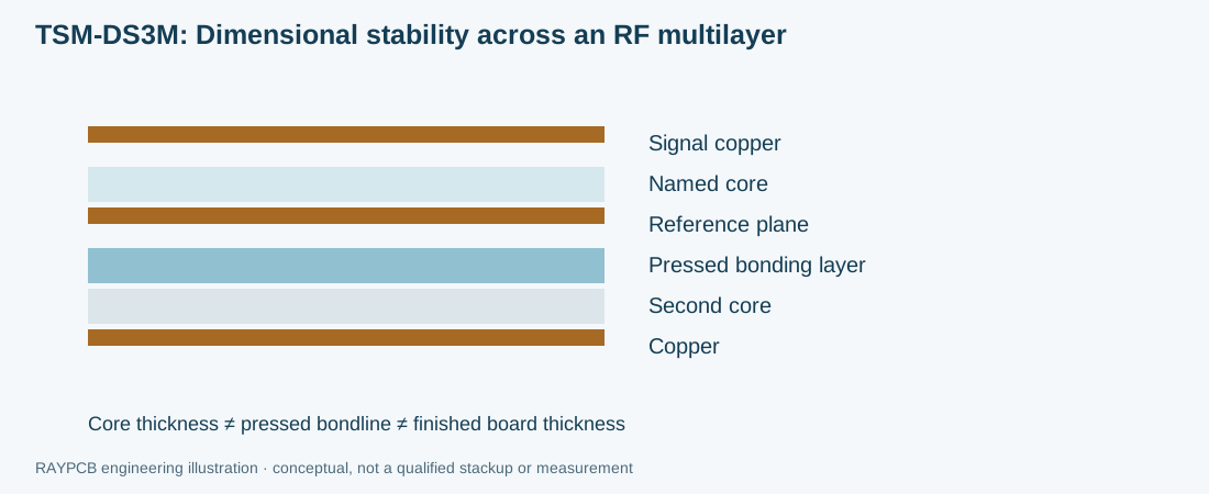
Dimensional stability across an RF multilayer
Multilayer registration and thermal expansion matter alongside dielectric loss. A narrow coupled structure can be sensitive to changes in layer separation or alignment. Define the required conductor geometry and press construction before moving the design between laminate variants.
- Check phase length after a core change
- Use the DS3M source for procurement
- Include test coupons when agreeing fabrication tolerances
RAYPCB ENGINEERING
Taconic RF EngineeringTaconic PCB Design Workbench
Loading Taconic PCB Design Workbench…
The RF tool uses an editable model Dk; the preset is a supplier reference at its stated method and frequency. It is not a universal design Dk. Blank parameters stay blank until you provide a value. Geometry calculations do not approve a fabrication tolerance.
For microstrip, h is the dielectric separation to the reference plane; for symmetric stripline it is the total plane spacing. Propagation follows λg = c/(f√εeff). Thermal screening uses R = h/(kA). Read the selected model’s exclusions beside the result.
For more geometries and fabrication tolerance context, use the PCB impedance calculator and design guide.
From material callout to fabricated PCB
01
Material release
Name TSM-DS3M, the supplier revision, thickness and foil. Separate approved substitutions from suggestions awaiting approval.
02
CAM and stackup
Review layer references, panelization, copper balance, minimum features and finished geometry. Check phase length after a core change.
03
Process definition
Use the applicable laminate and bonding guides. Agree drilling, hole-wall treatment and lamination details for this construction; do not assume a universal FR-4 recipe.
04
Patterning and final build
Control conductor geometry, hole quality, mask openings and finish on exposed RF areas. Include special edges, cavities or connectors in the release.
05
Inspection and acceptance
Define dimensional, netlist and impedance checks. RF loss or phase measurements need a separate coupon/fixture, frequency range and acceptance limit.
Review the manufacturing capability tables for general process limits and quality documentation and acceptance planning for supplier review. A listed material property is not a RAYPCB test report.
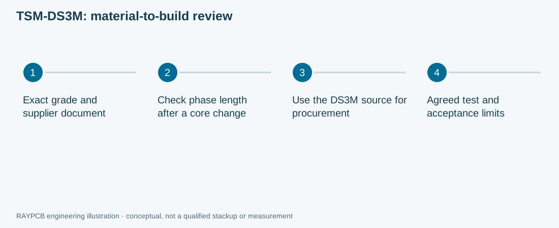
TSM-DS3M PCB cost & quotation brief
A quote for TSM-DS3M depends on the approved material construction, purchased sheet utilization, quantity, layer count, drilling/lamination work, finish and inspection scope. There is no defensible fixed “Taconic multiplier” across these products. For older designations, sourcing confirmation may be the first cost decision.
RAYPCB ENGINEERING
Taconic RF EngineeringTaconic PCB Cost & Quotation Brief
Loading Taconic PCB Cost & Quotation Brief…
Use the brief without prices, or enter your own setup and fabrication-area allowances to explore a simple two-layer planning range. The tool does not contain verified current supplier rates. Hybrid, multilayer, bonding-film and RF-qualified builds are routed to engineering quotation.
| Cost question | Information to provide |
|---|---|
| Material | Exact code, thickness, foil, substitutions allowed or prohibited |
| Fabrication | Gerber/ODB++, drill data, stackup, copper, outline and special features |
| Acceptance | Net classes, impedance target/tolerance and any RF test fixture |
| Order | Quantity, requested delivery date, repeat-build needs and assembly scope |
TSM-DS3M questions before ordering
What does the TSM-DS3M material name guarantee?
It identifies a material or family to resolve in the supplier documentation. The exact code, thickness, foil and data-sheet revision still need to be specified. It does not guarantee RAYPCB stock, lead time or an application qualification.
Which Dk should I use in my RF model?
Dk/Df: current AGC guide at 10 GHz. Use a model Dk appropriate to your geometry and frequency. A process test value is useful reference data but is not automatically the effective permittivity of a microstrip.
Can I replace TSM-DS3M with another Taconic or Rogers grade?
DS3M is not a 3.00-Dk DS3 core. A geometry transfer between them needs recalculation. Compare the complete electrical, mechanical and processing requirements, then approve the alternate explicitly.
What design detail deserves the first review?
Check phase length after a core change. Agree panel compensation from the actual laminate and process.
Does a netlist test verify RF performance?
No. Netlist testing checks connectivity. RF performance requires defined measurement structures, frequency range, reference planes and limits. State the required measurement in the RFQ.
How do I obtain a usable quotation?
Send the fabrication files, drill data, stackup, exact material code, quantity and acceptance requirements. Include your requested date; the delivery commitment depends on sourcing and process review.
Next useful references: Taconic PCB manufacturing · full Taconic material directory · TSM-DS3 · TSM-DS3b.
Send the design with its material context
Preliminary files are welcome. Identify the design revision and open material decisions so the enquiry can address the actual manufacturing scope.
Send TSM-DS3M files for review