
RAYPCB · ENGINEERING GUIDE
Shengyi S1000 PCB: Mid-Tg FR-4 Data and Stackup Review
Shengyi S1000 PCB material is a mid-Tg, lead-free-compatible FR-4 laminate family. The useful selection question is whether its exact construction fits the board's thermal exposure, interconnects and electrical requirements. It is not a heat sink, and the S1000 name does not establish the properties of S1000H, S1000-2 or other neighboring grades.
This page brings the source-qualified data into a practical stackup and purchasing review. For the broader supplier range, use the Shengyi PCB material overview. If the drawing already names S1000, start with its revision and supplied form before evaluating alternatives.
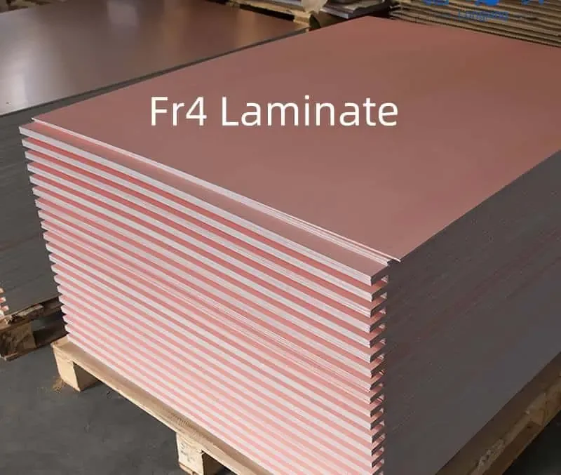
Read S1000 thermal data as separate measurements
The cited official product page reports typical Tg of 155°C by DSC, Td of 335°C at a 5% mass-loss criterion, and integrated Z-axis expansion of 3.4% over 50–260°C. These measurements describe different responses. Tg concerns a transition in the polymer system; Td concerns decomposition under a specified test; integrated expansion describes dimensional change over a temperature interval.
None is a continuous operating-temperature limit. Do not use a favorable Tg to justify an arbitrary soldering profile or assume that it prevents component overheating. The board's copper, thermal paths, hole construction and assembly history still matter. Retain the original specimen and method notes when translating the data into project requirements.
Source-qualified material review
| Item | Published information or evidence status | Design implication |
|---|---|---|
| Tg | 155°C, DSC, typical | Not a continuous operating temperature. |
| Td | 335°C, 5% mass-loss criterion | Preserve test definition; not reflow approval. |
| Z expansion | 3.4%, 50–260°C, typical | Different from an in-plane CTE. |
| Dk / Df | 4.9 / 0.011 at 1 MHz on the cited product page | Do not transplant these values into a GHz design model. |
Establish the stackup before discussing replacement
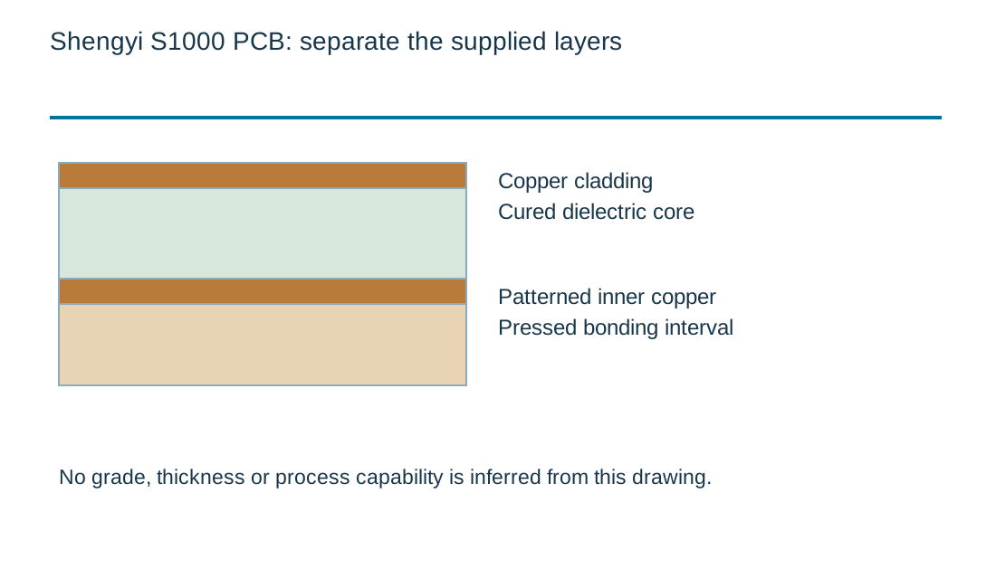
A material order should identify the laminate, matching bonding material, cured core thicknesses, copper foil and intended pressed dielectric intervals. An overall 1.6 mm board can contain many different internal constructions. Two suppliers can quote the same nominal board thickness while proposing different glass styles and resin distributions.
Ask for the proposed stackup alongside the material identity. Mark controlled-impedance layers, heavy copper regions and significant thermal exposures. If the proposed change is to S1000-2, compare the complete construction and required evidence; a higher temperature headline alone does not establish a drop-in replacement.
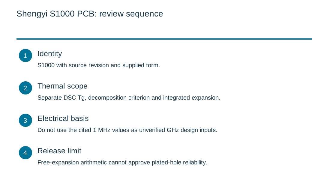
| Review item | What to establish |
|---|---|
| Identity | S1000 with source revision and supplied form. |
| Thermal scope | Separate DSC Tg, decomposition criterion and integrated expansion. |
| Electrical basis | Do not use the cited 1 MHz values as unverified GHz design inputs. |
| Release limit | Free-expansion arithmetic cannot approve plated-hole reliability. |
Keep low-frequency Dk out of an unverified RF model
The official page's Dk 4.9 and Df 0.011 are associated with 1 MHz data. They should not be inserted into a GHz channel calculation simply because they are easy to find. Frequency, test fixture, conditioning and resin content can change the interpretation of electrical data.
For a digital board, ask which design value and construction the field solver uses. For a loss-sensitive route, compare complete line attenuation including copper and transitions. If no relevant electrical data is available, record that gap before fixing trace geometry. A calculation with precise decimals cannot repair an unsupported material input.
Piecewise free thickness expansion
Piecewise free thickness expansion
Use the current inputs and keep the assumptions
Start with the example only to inspect the units and the calculation boundary. Replace every assumption with a value tied to your own document or measurement. An empty numeric field is not zero. The review-reference field is a local label; avoid entering customer names, confidential part numbers or other private information into a public worksheet.
After calculating, read the notes alongside the numerical result. Changing any input invalidates the displayed result and disables its download until you calculate again. For a comparison, keep the units, geometry, material condition and measurement boundary consistent. A long decimal result does not imply equally precise input data. The downloadable record stays on your device and can be attached manually to an inquiry. It is not automatically transferred into the Contact form.
If an input is unknown, identify the person or document needed to resolve it. Do not fill a gap with a favorable generic value simply to obtain a result. You can request a material or fabrication review without using the tool. The arithmetic illustrates a relationship; it does not accept a construction, certify a material, establish current pricing or replace a supplier process specification.
| Input | What to establish before using it |
|---|---|
| Review reference | Nonconfidential revision label. |
| Initial dielectric thickness · mm | Unconstrained specimen approximation. |
| Start temperature · °C | Must be less than final temperature. |
| End temperature · °C | Heating illustration only; not an approved exposure. |
| Assumed transition temperature · °C | Simplified sharp transition; use a defined measurement method. |
| CTE below transition · ppm/°C | Direction-specific value over the relevant interval. |
| CTE above transition · ppm/°C | Direction-specific value, not copied from in-plane CTE. |
Optional cost comparison from your own allowances
Use a quotation or a clearly labeled internal assumption for each input. Keep the quantity, construction and inspection scope the same when comparing alternatives. This uncalibrated planning model adds entered values; it contains no current market rates and does not issue a RAYPCB quotation. You can contact the team without completing it.
Optional project allowance comparison
Use thickness expansion to frame the via discussion
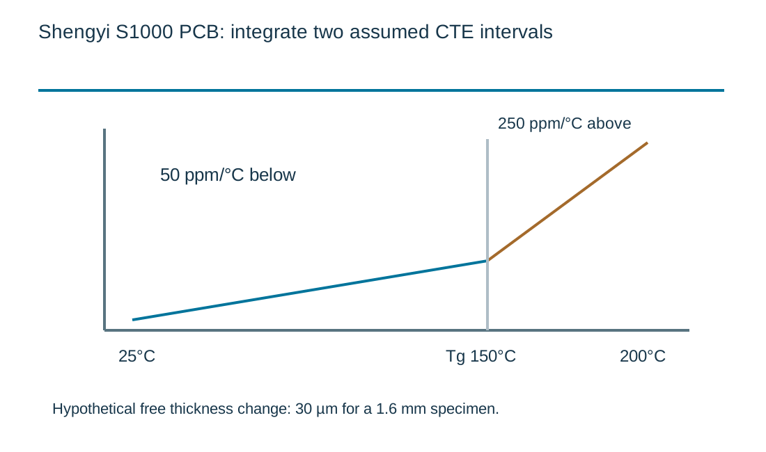
The engineering worksheet integrates two entered CTE values around an idealized transition. Its default values are hypothetical and are not a built-in S1000 profile. With 1.6 mm thickness, a 25–200°C excursion, a 150°C transition, and 50/250 ppm/°C coefficients, the free thickness change is 30 µm. That example is useful for checking units, not predicting plated-hole life.
Copper barrels constrain the laminate, while actual transitions are distributed rather than perfectly sharp. Plating quality, hole aspect ratio, copper thickness and repeated exposure need their own review. Supply the full heating history and hole architecture when asking whether a construction is appropriate.
Make the cost comparison on equal terms
A lower laminate purchase price does not necessarily reduce the accepted-board cost. Panel utilization, layer structure, process allowances and agreed testing can change the comparison. Separate one-time tooling from recurring board and inspection allowances. Enter only values supported by your quote or clearly labeled internal assumptions in the optional budget tool.
If the comparison involves S1141 conventional FR-4, check its explicit application exclusions as well as cost. If halogen composition is a fixed customer requirement, examine a documented route such as S1150G rather than assuming lead-free compatibility proves halogen-free composition.
Prepare an answerable S1000 inquiry
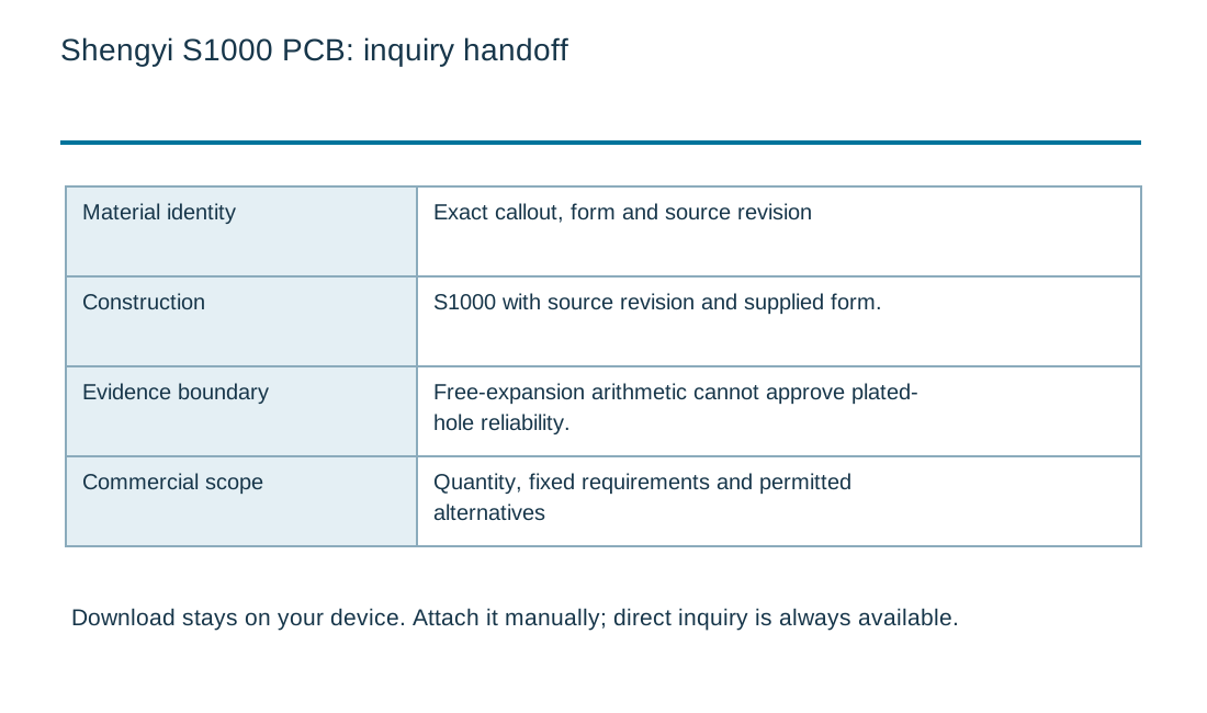
Send the drawing revision, stackup, dimensions, quantity, finished copper, surface finish and relevant assembly exposures. State whether the exact grade is mandatory or whether alternatives can be reviewed. Include the electrical test conditions and required material records, especially for a repeat program.
A useful response should identify the proposed material and construction, open exceptions and the evidence needed before release. Keep the approved answer with the fabrication package. The source values on this page support screening; current availability, supplied-lot requirements and manufacturing suitability still need confirmation for the actual order.
Close the material and construction decision together
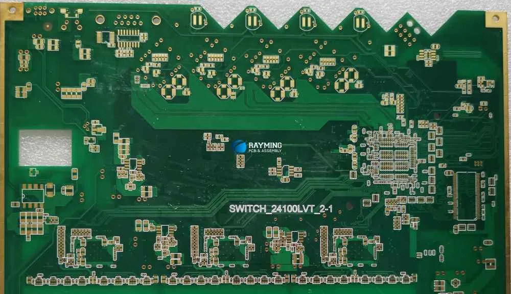
The finished board combines a dielectric, copper patterns, holes, surface coatings and a manufacturing history. Its behavior cannot be inferred from a family name alone. State the supplied grade, reinforcement, thickness, copper and processing conditions that matter to the intended application.
Keep handling and assembly requirements with the fabrication drawing. A thin panel, punched outline or unusual support condition can change the production route even when the electrical circuit is simple. Ask the fabricator to review the actual features and panel format rather than assuming a dimensional example represents a production capability.
For cost comparison, hold the drawing, quantity, test scope and acceptance requirements constant. Record one-time tooling separately from recurring work, and distinguish raw material utilization from accepted-board yield. Any calculator on this page uses supplied assumptions; an actual quotation requires the files and an agreed scope.
A source-qualified table should be read alongside the exclusions and footnotes, not separated from them. If the supplier limits an application, identify whether that limitation affects the current design before requesting a price. A familiar family classification does not override an explicit restriction, and a positive calculator result cannot remove it.
For a repeat build, compare the newly proposed supply with the previously approved material record. Exact grade, manufacturing site where relevant, foil treatment, reinforcement and dimensional basis can matter. Define which changes require notification and which need technical approval. This avoids turning a purchasing substitution into an unnoticed design change.
Receiving records should support the agreed identity and traceability requirement. A certificate for a raw material, a finished-board inspection report and an assembly test result cover different boundaries. Request the records that actually answer the project questions rather than collecting unrelated certificates.
When a source contains conflicting values, keep the discrepancy visible until a controlled revision or written supplier response resolves it. Do not create a new table by combining the most favorable entries from several sources. The released drawing, material list and quotation should all describe the same accepted construction.
Standards, source context and limits
Use the edition, amendment and material-document revision named in the purchase agreement. A standards title, marketing label or supplier product family does not establish that a particular lot meets a requirement. Public summaries are useful for scope; the controlled specification and applicable test method govern acceptance.
The examples on this page are illustrative engineering scenarios. They are not RAYPCB production records or guaranteed material values. Source links identify the organizations responsible for the referenced information. Confirm applicability to the exact grade, construction and test condition before carrying a number into a drawing or qualification report. Sources were reviewed on 3 October 2026. A public catalog search is not proof that an unlisted product never existed. Where the exact designation or current technical sheet could not be verified, this page provides a clarification workflow rather than an invented material specification. Current supply, construction availability and qualification remain separate questions.
For fabrication scope and the agreed construction requirements, see PCB manufacturing.

