
RAYPCB · ENGINEERING GUIDE
RF Laminate Heating: Loss and Device Thermal Paths
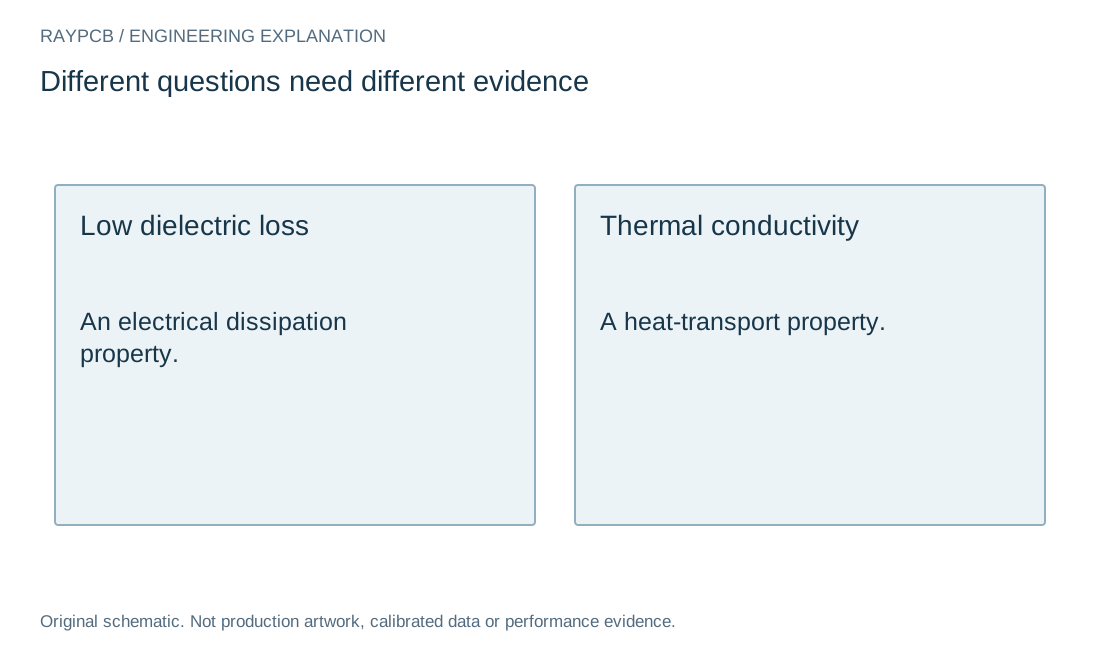
RF laminate heating can arise from losses in a passive structure, while an active device also converts part of its supplied power into heat. These mechanisms should not be collapsed into a single claim that lower-loss laminate always solves device temperature rise. Dielectric loss and thermal conductivity are different material properties.
This page provides an energy-accounting workflow. The passive-network worksheet separates reflected, transmitted and unaccounted power from entered S-parameter magnitudes under a matched-output assumption. It does not assign every missing watt to dielectric heating or predict a junction temperature.
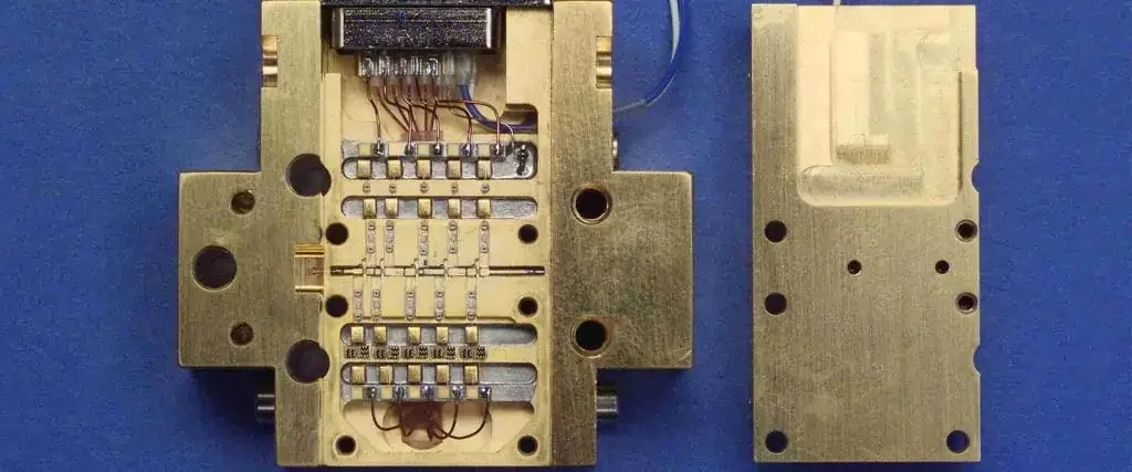
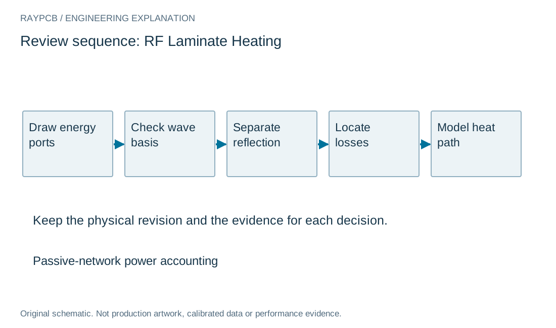
Draw the energy boundary before choosing a remedy
Identify all relevant inputs and outputs of the circuit under the intended operating condition. A passive transmission path, multiport antenna network and active power amplifier have different energy boundaries. Include the ports and mechanisms needed to interpret the missing power.
Keep average, pulsed and other power conventions consistent. A DC input measurement averaged over one interval cannot be compared carelessly with an RF peak value from another condition. Record waveform, duty cycle, bias and temperature where they influence the balance.
For an active stage, use the RF power-amplifier worksheet to account for DC and RF input as well as RF output. The passive tool on this page intentionally has no DC source. Applying it to a powered active network can produce an invalid interpretation even if the inputs look numerically plausible.
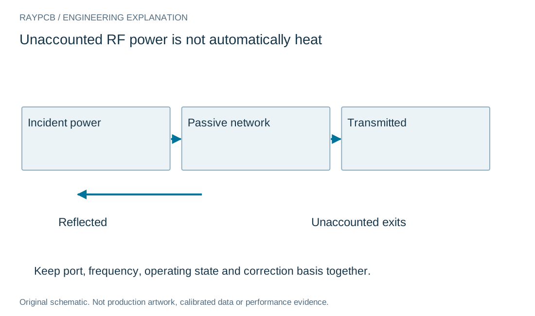
Power paths
| Quantity | Meaning | Limitation |
|---|---|---|
| Reflected | Returns toward input plane | Not automatically board heat |
| Transmitted | Leaves through measured output | Requires stated loading and normalization |
| Unaccounted | Remainder within chosen boundary | May include radiation or omitted ports |
| Device heat | Actual local dissipation | Needs active power and thermal boundary |
Distinguish reflection from dissipation
Power reflected at an input plane has not necessarily been dissipated in the board section beyond that plane. It may return toward the source and be handled elsewhere in the system. Treating insertion loss as dielectric heat without considering reflection can overstate the board's dissipation.
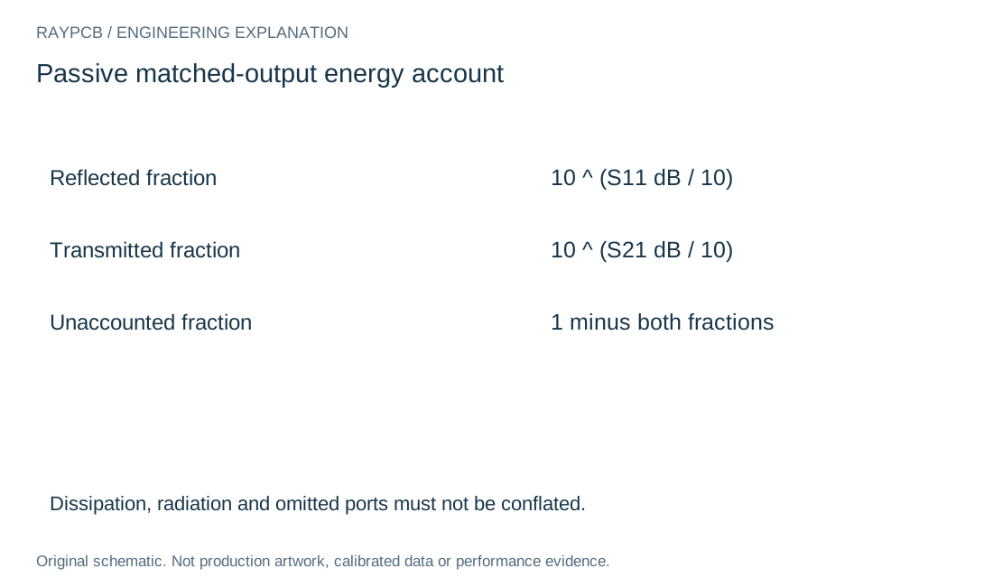
For a matched-output two-port reference with common real power-wave normalization, the squared magnitudes of S11 and S21 describe reflected and transmitted power fractions for the specified excitation. With values entered in dB, the tool converts to power ratios using the appropriate ten-to-the-dB-over-ten relationship.
The remaining fraction is labeled unaccounted. It can contain conductor or dielectric dissipation, radiation, leakage or power leaving through omitted ports. Establishing the physical allocation requires a complete boundary and additional evidence. The tool refuses combinations that imply excess output power in its passive model.
| Review item | What to establish |
|---|---|
| Boundary | Passive and active energy accounts are not mixed. |
| Power | Reflection, transmission and unaccounted energy remain distinct. |
| Heat | Loss tangent and thermal conductivity address different properties. |
| Evidence | Electrical and thermal comparisons retain consistent conditions. |
Passive-network power accounting
Passive-network power accounting
Use the current inputs and keep the assumptions
Enter your own values or use Load example to explore the clearly labeled teaching inputs. The example is not a measured RAYPCB project. Clear for my inputs starts a separate record. Fields identify the units and the physical boundary; missing or unsupported values need correction before a result is generated.
Changing an input invalidates the previous output and disables its download until you generate a new result. A worksheet cannot inspect a board, validate an instrument setup or approve manufacture. Keep its assumptions with any copied number.
Download the current text result if it helps explain a design question. The file stays on your device. Attach or paste it manually when contacting the team; no project information is automatically transferred to the Contact form. Completing this tool is optional.
| Input | What to establish before using it |
|---|---|
| Review reference | Nonconfidential scope or revision. |
| Incident RF power · W | At the input reference plane. |
| S11 magnitude · dB | Nonpositive for the passive reference. |
| S21 magnitude · dB | Matched output and common real power-wave normalization. |
Use the passive worksheet with its assumptions visible
Enter incident power at the defined input reference plane and the measured or modeled S11 and S21 values at the same frequency. The worksheet assumes the output is matched and uses a common real power-wave normalization. It does not solve a mismatched connected system from three scalar inputs.
Retain port mapping and calibration details with the source data. If a fixture or connector is included in the S-parameters, the resulting balance includes that boundary. If the data was de-embedded, preserve the method. Avoid mixing one value for the bare route with another value for the entire assembly.
Inspect the result as a consistency check and a starting allocation. A positive unaccounted value is not proof that the laminate is the dominant heat source. Use thermal measurements, appropriate modeling or a more complete network analysis to locate the mechanism before changing materials.
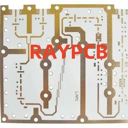
Separate dielectric, conductor and transition losses
A passive path's total behavior includes its material, copper geometry, conductor surface, finish and discontinuities. A change in measured insertion loss does not automatically reveal which mechanism changed. Compare controlled constructions and retain the conditions that could influence the result.
Lower dielectric loss can be useful when dielectric dissipation contributes meaningfully to the circuit limitation. It does not guarantee a lower temperature at an active device whose main heat path is elsewhere. Likewise, improving a thermal interface does not automatically reduce RF conductor loss.
The microwave substrate guide connects construction details to circuit structure. For higher-frequency copper and tolerance questions, use the mmWave material page. These tasks should inform the thermal investigation without becoming unsupported universal material rankings.
Model heat flow through the installed construction
Identify the heat sources and the paths to the environment: package interfaces, solder, vias, board layers, mechanical contacts and cooling arrangement. A temperature rise depends on that system and the operating condition, not only on the laminate's thermal-conductivity number.
Use thermal parameters under conditions consistent with their definitions. A package value measured on a particular test board or mounting arrangement should not be treated as an exact installed-product prediction. Record ambient, airflow, duty cycle and interface assumptions with any model result.
Coordinate electrical and thermal changes. Adding copper, vias or a heatsink can alter RF geometry or nearby fields. A proposed thermal improvement should therefore receive the relevant electrical review rather than being assumed invisible to the antenna or transmission path.
Design a comparison that identifies the cause
Retain a baseline and vary one important feature where practical. Compare electrical loss and temperature under the same operating condition. If the layout, material, copper and cooling all change together, report a system-level comparison rather than assigning every improvement to the laminate.
Keep measurement limitations visible. Temperature observation method, sensor attachment, emissivity assumptions where relevant, thermal settling and RF calibration can affect the conclusion. An attractive thermal image or one low insertion-loss trace is not a complete validation record.
Inspect representative units or conditions when repeatability matters. Contact pressure, solder interfaces and mounting variation can change thermal behavior even when the board material is identical. Distinguish process variation from the intended design effect before freezing the next release.
Convert the result into a useful manufacturing request
Specify the actual stackup, copper construction, thermal features, assembly interfaces and requested verification. Identify which dimensions and materials are fixed by RF or thermal evidence. A general request for low-loss, cool-running PCB does not define the construction to quote.
Provide the operating condition and relevant analysis or test summary when it explains a constraint. Keep unverified assumptions labeled and state who owns the next validation step. Fabrication review can assess a proposed construction, but it does not automatically approve the complete product temperature or RF performance.
Contact RAYPCB with current files, quantity and the particular material, thermal or assembly question. The energy worksheet is optional and its text output remains local for manual attachment. It helps keep the power accounting understandable while leaving unsupported heat or performance claims out of the enquiry.
Do not label every missing watt as laminate heat
A power balance is only as complete as its ports and normalization. Reflected energy, radiation, leakage and omitted paths can affect the interpretation. Keep unaccounted power labeled honestly until a fuller model or measurement establishes where it goes.
For the thermal decision, identify the actual heat sources and interfaces. A lower RF loss and a better heat-removal path are complementary possibilities that require different evidence. Choose a change against the mechanism rather than the most attractive material property.
Standards, source context and limits
Use the current document for the exact selected component, construction and test method. A vendor application note is not a universal fabrication rule. Agree any applicable acceptance standard and edition for the project; these public references do not certify a board or reproduce licensed acceptance criteria.
Photographs are identified as existing site archive context. They do not establish current factory ownership, calibrated results or a customer's product performance. Original diagrams explain the named engineering boundary and are not production artwork or field-solver output.
For fabrication scope and the agreed construction requirements, see PCB manufacturing.