
RAYPCB · ENGINEERING GUIDE
QFP vs QFN: Footprint, Soldering, Inspection and Design Tradeoffs
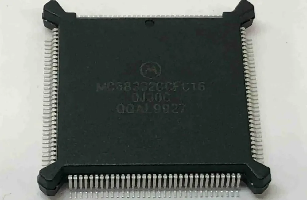
QFP packages use leads that extend from the body, while QFN packages use leadless terminations around the underside or edges of the body. This changes the board interface, paste design and inspection approach. It does not make every QFN electrically equivalent to a QFP with a similar function or terminal count.
Use this comparison during component selection or a package change. The area tool compares entered occupied envelopes; it cannot decide pin compatibility, thermal performance or assembly qualification. Those decisions need the exact component and package documentation.
Compare complete outlines, not just body size
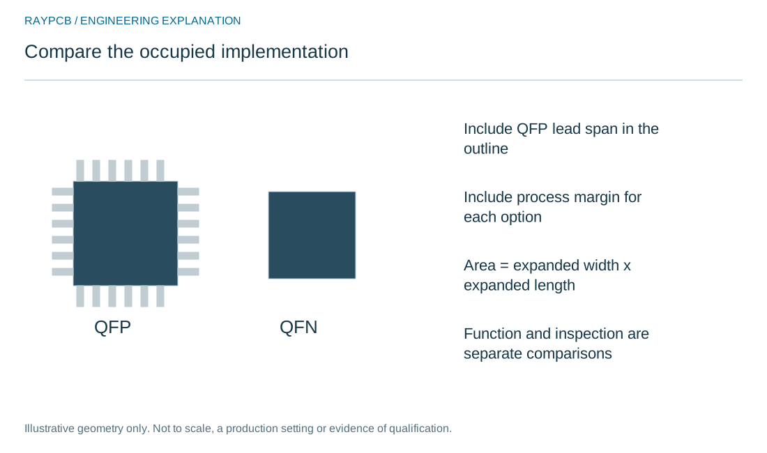
A QFP's lead span can occupy considerably more board area than its molded body. A QFN may have a compact external outline but still need surrounding space for routing, inspection and rework. Include the actual termination envelope and relevant keepouts when comparing candidate placements.
The worksheet applies the same entered additional margin to two rectangular outlines to make the geometric comparison transparent. If a 12 by 12 mm option and an 8 by 8 mm option each receive 1 mm per side, the review areas are 196 and 100 mm². These are illustrative envelopes, not standardized courtyards or proof that the smaller option is the better design.
Check pin assignment before changing package
Obtain the exact orderable suffixes, pin maps and recommended land patterns. A package alternative can change electrical pin positions, exposed-pad connection, thermal resistance or supported performance conditions. The board may need rerouting and verification even when the device family name remains the same.
Keep the schematic-to-pad mapping under revision control. Do not substitute a QFN for a QFP solely because purchasing finds the same functional description. A package change affects the physical and potentially electrical interface and should be approved as an engineering change.
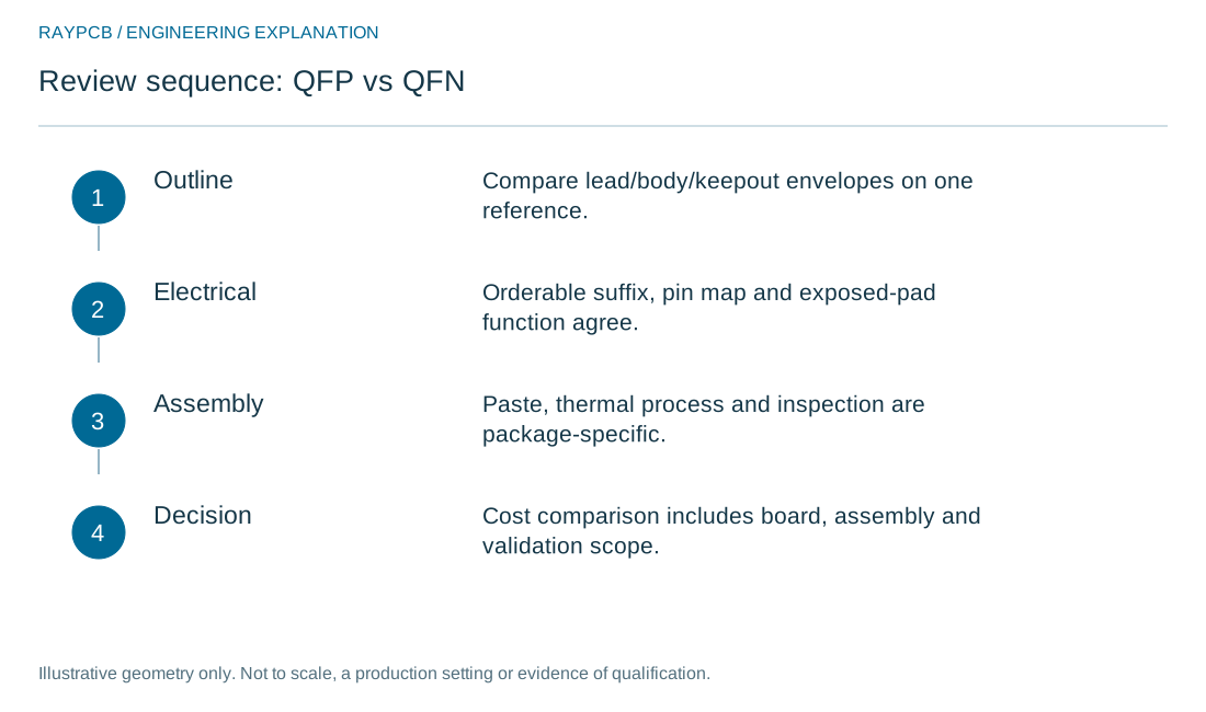
| Review item | What to establish |
|---|---|
| Outline | Compare lead/body/keepout envelopes on one reference. |
| Electrical | Orderable suffix, pin map and exposed-pad function agree. |
| Assembly | Paste, thermal process and inspection are package-specific. |
| Decision | Cost comparison includes board, assembly and validation scope. |
Package keepout-area comparison
Package keepout-area comparison
Use the current inputs and keep the assumptions
Choose the question you want to resolve before entering numbers. The fields start blank. Load example deliberately if you want to understand the calculation, and keep that example separate from your project record. The example label remains visible after editing; reset the tool before preparing a record from your own data.
Use the displayed units and identify the source of each input. A dimension should refer to the same layer, reference plane and design revision as the other dimensions in the model. An entered limit is your review requirement, not an IPC value supplied by this website. Where a value is unknown, obtain it or preserve the question as open instead of guessing a familiar number.
Read the assumptions with the result. A negative margin is retained so a conflict remains visible. A positive margin only answers the stated mathematical question. It does not establish process capability, compliance, electrical performance or production yield. Checklist statuses are self-reported and do not imply that the underlying evidence has been inspected.
Changing a field invalidates the result and disables its download until you calculate again. The text download contains the current inputs, result and limitations. No CAD file is read, no project data is uploaded and nothing is automatically inserted into Contact. Attach the record manually if useful. You can request a review directly without using the worksheet.
| Input | What to establish before using it |
|---|---|
| Review reference | Connect this worksheet to a nonconfidential design/revision reference. |
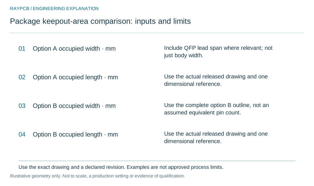
| Option A occupied width · mm | Include QFP lead span where relevant; not just body width. |
| Option A occupied length · mm | Use the actual released drawing and one dimensional reference. |
| Option B occupied width · mm | Use the complete option B outline, not an assumed equivalent pin count. |
| Option B occupied length · mm | Use the actual released drawing and one dimensional reference. |
| Additional allowance per side · mm | Same illustrative allowance for both options; process-specific keepouts can differ. |
Treat the exposed pad as a separate requirement
Many QFNs include an exposed central pad, but its function and required connection depend on the component. It may provide a thermal or electrical connection that must follow the datasheet. The land, thermal vias and paste pattern work together; a large uninterrupted paste opening is not automatically appropriate.
NXP's QFN/SON assembly guidance illustrates why board design, printing, placement and reflow should be considered together. Use the separate QFN printing guide for deposited-paste review, and the existing QFN stencil-design page for aperture design. This comparison does not replace those focused tasks.
Plan for different inspection visibility
QFP leads often provide accessible features for optical inspection, although visibility does not guarantee electrical correctness or reliability. QFN bottom connections can be less visible, and side wetting depends on the actual termination construction. Do not require a visible side fillet on every QFN without checking whether the package is designed to provide one.
Define inspection and testing around the chosen package and failure risks. Hidden exposed-pad joints may need a different evidence method from visible peripheral leads. Record what the method can detect and what remains outside its coverage instead of treating one inspection image as complete acceptance.
Consider placement and rework together
Package recognition, coplanarity, paste deposition and local board support all affect assembly. Leaded packages introduce lead handling and alignment considerations, while leadless packages depend on the board and paste interface beneath the body. Keep the component supplier's restrictions on handling and thermal exposure available to production.
Reserve a practical rework approach if replacement is part of the product strategy. A compact placement that blocks local heating or removal can turn a replaceable component into a difficult repair. Where repair is not intended, agree on disposition and cost consequences during design rather than after a failed prototype.
Compare cost with the assembly included
Evaluate component sourcing, board area, routing complexity, stencil work, inspection and qualification together. The difference in device price is only one line in that comparison. A smaller package can save board area while adding process development or inspection work, and a larger package can create an enclosure or routing penalty.
Send RAYPCB the two exact package candidates, current layout, quantities and the intended verification scope. The SMT footprint checks help establish that each option is represented correctly. A useful response is a scoped comparison of actual interfaces and operations, not a universal statement that QFN or QFP is always superior.
Compare complete alternatives rather than labels
Write down the function the component or assembly route must deliver. Then identify the exact alternatives being compared. Similar package names, pin counts or body areas do not establish electrical interchangeability. A useful comparison starts with specific part numbers and their documented interfaces, not a general ranking of one acronym above another.
Compare the complete occupied region on the board. Include terminals, escape routing, supporting parts and the process space that the selected assembly method needs. If the comparison is about serviceability, identify how the part or assembly will actually be removed and replaced. A socket can change both the mechanical envelope and the electrical interface.
Keep production consequences visible. Printing, soldering, inspection and test may differ between alternatives. Some interfaces expose joints to visual inspection, while others require different evidence. None of those observations alone establishes total quality; they help define the appropriate verification plan for the product.
Purchasing should compare approved, available configurations with a clear substitution process. A lower component price can be offset by a different board construction or additional assembly operations. Conversely, a more expensive component can sometimes simplify the implementation. Use actual scoped quotations or clearly labeled internal allowances, rather than a universal claim about which package is cheapest.
Review the product environment and expected changes over its life. Mechanical loads, temperature conditions, repair policy and recurring supply needs can influence the choice. A successful prototype does not automatically settle those questions for production, especially when the component or assembly route changes.
End the comparison with a decision and the evidence still required. If the selection is provisional, say what would change it. This creates a useful next step for an engineering enquiry: the alternatives, constraints and unresolved question can be reviewed together, instead of asking a supplier to endorse a broad package category without seeing the actual design.
Standards, source context and limits
The references below support the stated package, design or process context. Apply a component manufacturer's guidance to its named device or family and confirm the exact drawing revision. A supplier application note is not a universal manufacturing rule, and a public standards scope is not the complete controlled standard.
Agree the governing documents, revision basis, acceptance requirements and exceptions with the responsible engineering and quality teams. The official IPC revision table is useful for checking document status; it does not by itself resolve a project's contractual requirements. This page does not reproduce paid normative tables or claim certification.
Archive photographs illustrate relevant boards, components or assembly activity. They are not proof of the current equipment inventory or a completed qualification for your project. The explanatory drawings and worked examples are original teaching aids. Confirm actual process availability and the proposed inspection scope during the project review.