
RAYPCB · Flexible circuit engineering & manufacture
Multilayer Flex PCB: Compare Construction Options
Choose the structure that resolves the routing and installation problem.
Compare multilayer flex candidates with the same interface, mechanical constraints and acceptance requirements.
Candidate A
State the electrical and mechanical requirements.
Candidate B
Compare under the same requirements.
Choose what you need to resolve
Use a check below, or send existing files directly. You do not need to finish the worksheet to enquire.
Compare architectures before choosing more layers
| Candidate | What it can help resolve | What still needs proof |
|---|---|---|
| Continuous multilayer flex | Signal/reference allocation and dense interconnection across a defined outline. | Regional thickness, layer continuity, bend constraints and the agreed manufacturing process. |
| Separate supported and bending regions | Local component or connector support while retaining a defined flexing region. | Actual physical transition, copper continuity and local finished-thickness requirements. |
| Rigid-flex alternative | Combine rigid component areas with integral flexible interconnects. | Approved rigid-flex stackup, interface constraints and complete cost/test scope. |
Record each candidate using the same outline, electrical interfaces and mechanical duty. Save A/B snapshots in the worksheet; changing a copper count alone does not create a valid new stackup. A six-layer region does not imply that every moving region should contain six copper layers.
For four copper layers, compare the intended L1/L2 and L4/L3 signal/reference relationships against a different routing allocation; the layer-role labels do not set dielectric spacing or verify impedance. For six layers, document which conductive layers cross every physical region and why.
Multilayer flex selection connects to four-layer constructions, six-layer requirements and rigid-flex options. Use the regional stackup reference to document the physical layers.
Compare your construction candidates
Use only the checks your project needs. Already have files? Send your files directly for a quote.
No data is sent by this worksheet.
Carry Brief to Enquiry temporarily keeps this text in the same browser tab and adds it to the Contact message. Review it there and attach your actual files. No request is submitted until you send the form.
Project inputs stay in this tab. Carrying a brief uses temporary tab storage for up to 30 minutes; files are not transferred. Examples explain arithmetic and are not approved production stackups.
Multilayer Flex PCB: Layer & Construction Selection — design decisions
Multilayer flex uses more than two copper layers to support a denser interconnect. This page helps you decide which construction to discuss; the individual four- and six-layer pages cover their specific drawing and enquiry requirements.
| Choice | When to investigate | Next step |
|---|---|---|
| 2 copper layers | The required routing and return paths fit without extra layers. | Review double-sided flex |
| 4 copper layers | Additional routing or reference layers are needed. | Review four-layer flex |
| 6 copper layers | The layout needs a denser multilayer interconnect. | Review six-layer flex |
| Rigid-flex | Rigid component regions and flexible interconnections are required. | Compare rigid-flex construction |
Layer count is only one decision. Coverlay, adhesives, local stiffeners, bend duty, connection technology and dimensional tolerance determine whether the complete concept fits the enclosure and manufacturing route.
Three ways to solve a routing-density problem
| Concept | What changes | Question to answer before ordering |
|---|---|---|
| Two-layer flex with revised routing | No additional conductor layers | Can net ordering, connector pinout or outline changes make this feasible? |
| Four- or six-layer bonded flex | More conductors and dielectric throughout the flexible section | Does the increased thickness still meet the actual installation and motion requirements? |
| Rigid-flex with fewer continuing flex layers | Extra circuitry retained only in rigid regions | Can signals transition onto the smaller flex-layer set without an unacceptable electrical penalty? |
Layer count is a consequence of the electrical and mechanical design, not a performance score. Compare the four-layer section and six-layer section only after defining the bend region and supported areas.
A construction comparison that belongs in the RFQ
Ask for comparison of two feasible constructions when a routing decision is still open. State what must remain constant: outline, interfaces, electrical constraints, quantities and installation space. A price comparison between different functional requirements can be misleading.
Identify which candidate uses a uniform bonded construction and which requires local mechanical treatment. Neither the budget tool nor a product photograph verifies the process. Send the proposed flex stackup and layer artwork for engineering review.
Material selection starts with the actual laminate, copper and coverlay grades. Refer to DuPont’s laminate portfolio and the supplier drawing for each selected grade. Kapton and Pyralux are not interchangeable names for every flexible circuit material.
Questions to resolve before ordering
How should I choose between four and six layers?
Start with actual routing and electrical requirements, then compare regional thickness and mechanical constraints. The lowest layer count is not always the lowest complete-project cost.
What does the A/B tool establish?
It sums entered constituent thicknesses and allowances and preserves snapshots. It does not model impedance, adhesive flow, manufacturing yield or fatigue life.
Product details for your design review
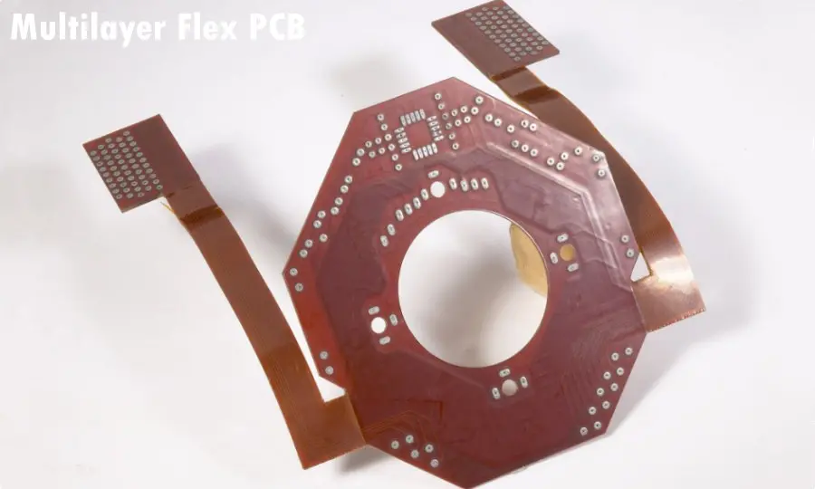
Existing RAYPCB gallery images illustrate circuit form. Ask for construction-specific records to establish layer count, material, tolerances and test results.
From a preliminary question to a build-ready enquiry
| Your project stage | Send what you already have | Define before release |
|---|---|---|
| Concept / budget | Application, sketch or approximate outline, installation/motion conditions and quantity range. Unknowns are welcome. | Candidate construction, unresolved dimensions, cost assumptions and whether assembly is included. |
| Design ready | Artwork, drill data, drawing/revision and requested quantity. Identify critical contacts, bend zones and inspection requirements. | Approved stackup, controlled revision, finish, tooling and inspection scope; confirm the lead-time starting conditions. |
| Assembly / transfer | BOM, placement and assembly information where available; supply responsibility, existing test baseline and known issues. | Permanent supports versus temporary carriers, first-article acceptance, test ownership, delivered shape and packaging. |
Compare the full quotation scope
Separate recurring manufacture from one-time tooling, carriers and test development. Compare the same material definition, finish, delivered state and acceptance evidence. A low unit price can exclude a carrier or inspection record required by your product. Request lead time against the actual materials, released files and agreed work; a target date is not a delivery guarantee.
Make sample approval useful for the next batch
Identify the drawing revision and acceptance criteria used for the first build. Record approved material substitutions and resolved engineering questions rather than relying on an email label such as “same as last time.” Ask which dimensional, electrical and construction records are included, which require separate development, and how changes will be approved before a repeat order.
Send your existing files directly, or generate a brief above and choose Carry Brief to Enquiry. Review the message and attach the actual files on Contact before submitting.