Double-sided PCB assembly: follow both reflow passes
Follow printing, placement, first reflow, board support and second reflow. Track component heat exposure and define inspection before releasing a double-sided build.
Preliminary files and open process questions are welcome.
A common sequential SMT route. First-side selection, support and inspection points require review for the actual assembly.
How are double-sided SMD boards assembled?
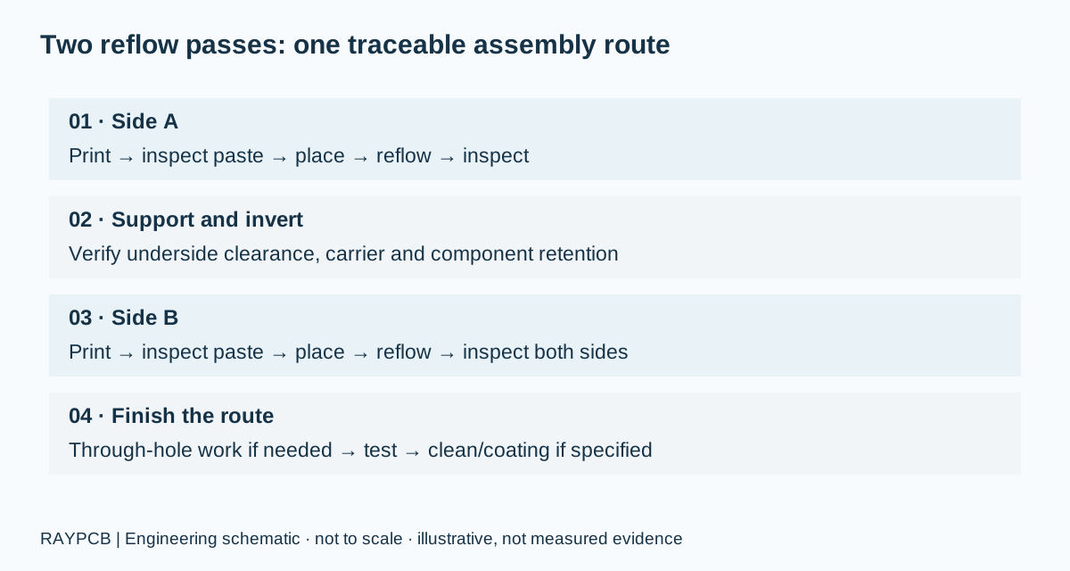
Double-sided PCB assembly normally uses two printing, placement and reflow operations. The first populated side is soldered, the board is inverted and supported, and the second side is populated and reflowed. Components mounted during the first operation experience the later heating cycle as well. The assembly route therefore needs a deliberate side order, underside clearance, component retention review and a thermal history for sensitive devices.
The second pass does not universally require a lower-melting solder alloy. Many designs use the same qualified solder system on both sides. The acceptable route depends on the package, board, paste, profile and mechanical conditions. Adhesive, carriers or alternative process sequences may be appropriate for particular components, but none should be prescribed simply because a board has two populated sides.
This page follows the manufacturing sequence. If you are still deciding whether the extra populated side is worthwhile, start with the single-sided versus double-sided SMT comparison. Component sides and copper-layer count are different decisions; a multilayer PCB may have either one or two populated sides.
Follow the two-pass route
Use the numbered explanation to follow the board through the main operations. Playback is optional, pauses when the explanation leaves view and respects reduced-motion preferences. The sequence is a conceptual process explanation, not a record of a particular production line. The accompanying checks identify the information needed at each handoff.
RAYPCB ENGINEERING
Double-Sided Reflow Explorer
Assembly Process Engineering
Loading Double-Sided Reflow Explorer…
At the planning stage, assign unambiguous side names that match the assembly drawing. “Top,” “bottom,” “first” and “second” are not automatically interchangeable. A CAD bottom side can be the first production side. The traveler, stencil files, placement data, inspection programs and operator views must all use the agreed mapping, including the viewing direction for mirrored bottom-side coordinates.
01 / ASSEMBLY STAGE
Release the files and decide the side order
Start with the fabrication revision, BOM, paste layers, component coordinates and assembly drawings. Identify do-not-populate parts, permitted substitutes, polarity marks and variant differences. Confirm panel rails and fiducials before generating production programs. A coordinate file that mixes board and panel origins can produce a visually plausible placement program with the wrong actual positions.
Side order is a manufacturing decision informed by component mass, attachment geometry, sensitivity, density and access. A simple instruction to place “all small parts first” can miss a moisture-sensitive package or a connector with unusual thermal limits. Review the actual component instructions and discuss any need for separate soldering, temporary support or a different assembly route.
Agree the first-build inspection and test plan before assembly starts. The PCBA file requirements help organize the release; the design for assembly review covers access and layout questions. Neither substitutes for approval of the specific component list and process sequence.
02 / ASSEMBLY STAGE
Print, inspect and assemble the first side
Support the bare panel so the stencil can seal consistently against the board. Aperture design, foil thickness, paste characteristics and local pad geometry determine the initial deposit. Excess paste can create problems that placement accuracy cannot correct; insufficient paste can leave joints that look aligned before reflow but do not form reliably.
Solder paste inspection checks the deposit before parts hide it. Placement then brings the component terminals into the intended relationship with the pads. Package orientation, fiducial recognition and feeder setup are distinct checks. Before a full run, verify the first assembly against the released drawing and retain the decisions made for any ambiguous or unusual components.
Reflow conditions must fit the paste and component requirements while producing the intended joints across the board. A controller setting is not a measurement of every component. Record a representative instrumented profile and relevant locations. After cooling, inspect the first side while access is available; hidden-joint packages may need a separate inspection method.
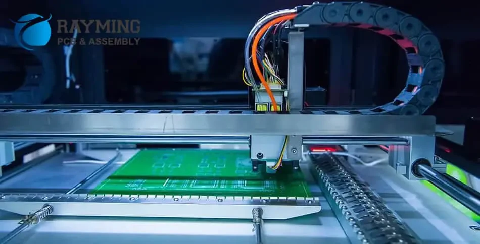
Original RAYPCB assembly equipment image. It illustrates the placement stage; no PoP package, pitch capability or production yield is inferred.
03 / ASSEMBLY STAGE
Invert the board without losing process access
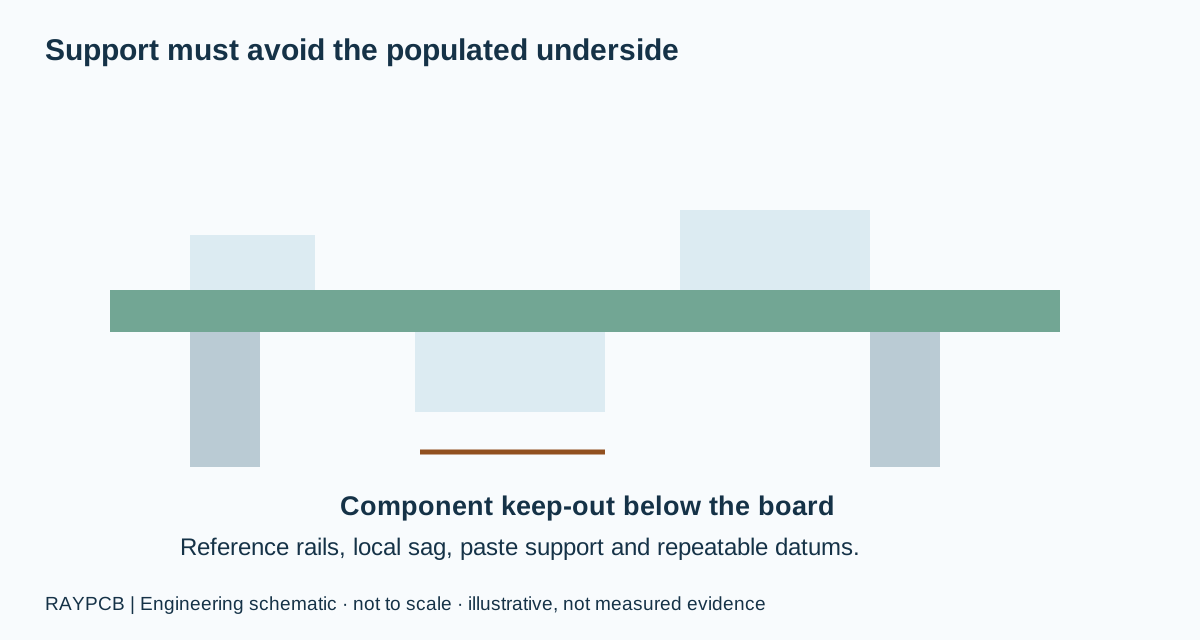
The populated underside changes how the panel can be held. Support pins, printer tooling, conveyors and carriers must avoid components and exposed connections. A carrier should locate the board repeatably without inducing excessive bow or covering regions that need printing, heating or inspection. Ask for a support drawing when the component arrangement makes ordinary tooling unsuitable.
The underside also matters during second-side reflow. Surface-tension forces can retain suitable components when their joints remelt, but retention depends on the component and joint system. A universal mass threshold is not sufficient because attachment area, wetting, package geometry, vibration and thermal conditions differ. Heavy or awkward components need a documented process decision.
Adhesive is an option to evaluate, not a universal requirement. Its placement, cure, compatibility and removal implications matter. Do not let adhesive cover solderable areas or assume that it corrects poor thermal control. The selected fixture or adhesive approach should be included in first-build trials and in the quotation scope if it adds material, handling or development work.
Conceptual support arrangement; tooling must be designed for component heights, panel stiffness and printer/oven fixtures.
04 / ASSEMBLY STAGE
Print and reflow the second side
Printing on a populated board requires a suitable underside support strategy. The second stencil and print program must correspond to the correct side and revision. Check local board deflection, paste release and separation, particularly where first-side components prevent support close to the active print region. Repeat the agreed paste inspection before placement.
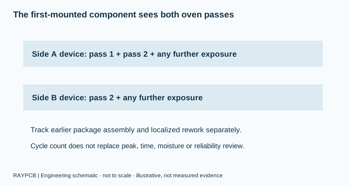
The second oven pass affects both sides, although only the newly placed side receives fresh paste in a conventional sequence. Confirm that the first-side solder joints, packages, markings and adhesives tolerate the planned exposure. Changes to panel loading or the support carrier can change the thermal response, so a first-pass profile cannot simply be relabelled as the second-pass profile.
Package-specific guidance is more useful than a single generic reflow temperature. TI maintains an SMT and packaging application-note directory for locating relevant assembly information. Use the current instructions for the actual device, including moisture handling and permitted thermal exposure; an example for one package family does not qualify other packages or an additional repair sequence.
Count only thermal cycles that the specific component actually experiences. A pass allowance is device-specific evidence.
Count component exposure before the next operation
This worksheet distinguishes a first-side device from a second-side device. Enter each device's earlier counted passes, any additional full-board passes planned after the two standard operations and the total allowance supported by the component documentation. The calculation identifies a count conflict; it does not qualify a thermal profile or authorize another repair.
RAYPCB ENGINEERING
Component Reflow-Pass History
Assembly Process Engineering
Loading Component Reflow-Pass History…
In a simple example with no earlier history and no later full-board heating, the first-side device experiences two passes and the second-side device one. If a further full-board reflow is planned, the counts become three and two. Those numbers describe the route; they are not a universal maximum. The example allowance of three must be replaced with actual component-specific evidence.
Keep localized rework in the engineering record even when it cannot be represented by a simple full-board count. Nearby components may receive substantial heat, and a package's time, peak temperature and moisture exposure remain relevant. A nonnegative remaining allowance in this worksheet is only an arithmetic result. It does not mean that cumulative reliability has been demonstrated.
05 / ASSEMBLY STAGE
Complete mixed assembly, inspection and test
Through-hole parts may be installed through a separately planned hand, selective, wave or other approved operation. Confirm whether those operations expose first-side or second-side components to additional heat. Nearby plastic connectors, sensitive sensors and underside pads can constrain the choice. Use the through-hole assembly process to plan that branch without treating it as an automatic third reflow.
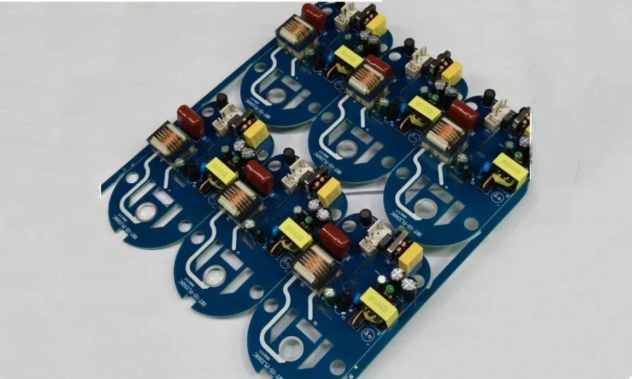
Existing RAYPCB project photograph from the assembly-preparation release. It shows a mixed component population; the particular soldering method is not identified by the photo.
Inspection coverage should account for the final two-sided condition. AOI can assess visible features; it does not make hidden joints visible. X-ray inspection addresses different questions and still needs a method suited to the package and defect of interest. Functional testing addresses operation rather than visual workmanship alone.
Cleaning, programming, coating and final handling must follow the agreed order. Coating can obstruct access to test points or connectors if the keep-outs are undefined. Record which surfaces and pads must remain accessible until testing is complete. Final packaging should protect exposed parts on both sides and prevent forces being carried through fragile components.
Compare the full two-sided build scope
The second populated side adds printing, placement, handling and thermal operations, but total price is not automatically twice the single-sided price. Board area, panel utilization, component mix, fixtures, inspection and acceptable output quantity also affect the comparison. A smaller two-sided board can reduce one cost while increasing another. Compare the same delivered function and test coverage.
Cost question
Information to provide
Why the answer changes the quote
Two paste programs
Paste layers and revision
Separate stencil, setup and inspection scope
Underside support
Component heights and no-contact regions
Standard support versus project tooling
Sensitive components
Part numbers and supplier instructions
Handling, profile development or separate installation
Hidden joints
Package locations and inspection requirements
Different inspection programs and coverage
Mixed assembly
Through-hole joint map
Additional route, fixture and handling
Repeat build
Approved process and change list
Reuse of validated setup versus new development
For a comparable request, attach the side order if it is fixed, the reason it is fixed and any permitted alternatives. Include prototype and repeat quantities separately. The PCB assembly cost guide helps separate setup, recurring work and verification. You can request a review directly without calculating an estimate first.
Questions before releasing a double-sided assembly
Must the second side use lower-temperature solder?
No. The metallurgy and process must be selected and qualified for the actual assembly. Introducing another solder system can create compatibility and reliability questions of its own. State the approved materials and ask the process engineer to review the complete sequence rather than treating lower melting temperature as a general solution.
Should every underside component be glued?
No. Retention should be assessed for the specific packages, joints and processing conditions. Unnecessary adhesive can complicate inspection, cleaning and repair. Where adhesive is required, define the product, application, cure, keep-outs and verification as controlled process requirements.
Can one placement file cover both sides?
A file can contain both sides if its format clearly identifies them, but production still needs unambiguous origins, units, rotations and viewing conventions. Include the assembly drawing so the receiver can verify the interpretation. Do not rely on filenames alone to define which side a coordinate belongs to.
What should the first-build report contain?
Request the records that resolve the identified risks: side mapping, approved material revisions, thermal profiles, support or carrier details, first-piece checks, inspection results and functional test outcomes where required. Agree the report contents before quotation so that manufacturing and acceptance have the same scope.
Review a double-sided build
Send the drawing revision, BOM, quantity and the process question you need resolved. Include component instructions, mechanical restrictions and required inspection or test records where relevant.
Tool use is optional. Attach any downloaded brief manually; Contact does not automatically receive worksheet inputs. References reviewed September 2026. Illustrations are explanatory, and photographs are not process qualification records.