
RAYPCB · ENGINEERING GUIDE
GNSS Antenna Integration: Gain, Noise and Interference
GNSS antenna integration requires attention to the antenna, losses before amplification, receiver requirements, bias arrangements and the product's interference environment. An active antenna with more gain is not automatically the best solution, and an apparently good antenna match does not establish reliable navigation performance.
This page focuses on the receive-chain boundary. For patch structure and polarization, use the L-band patch antenna guide. The worksheet here illustrates a passive input loss followed by a receiver under stated noise assumptions; it does not simulate satellites, acquisition time or positioning accuracy.
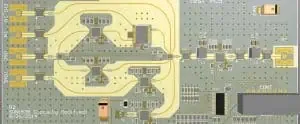
Define the signals and receiver interface
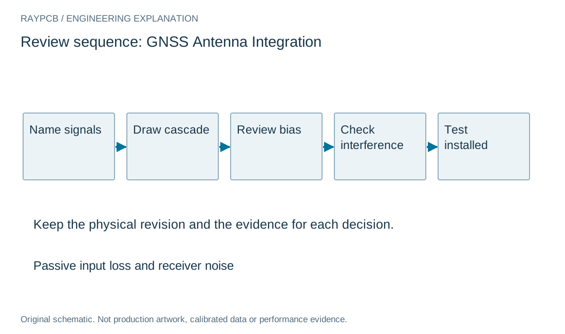
Identify the exact receiver and intended supported signals through its current documentation. Record antenna requirements, interface limits and the desired installation. A generic GNSS label can conceal differences in frequency coverage, filtering and active-antenna compatibility.
State whether the antenna is passive or includes an amplifier and other circuitry. Draw the complete path from the radiating structure through cable, protection, filtering and bias network to the receiver. Name the reference plane of each gain, loss or noise value used in the system review.
Use a current vendor integration document for the selected receiver and antenna. The u-blox GNSS antenna application note is useful general context, but its guidance still needs to be matched to the actual product. Do not treat a historical example as a current specification for every receiver family.
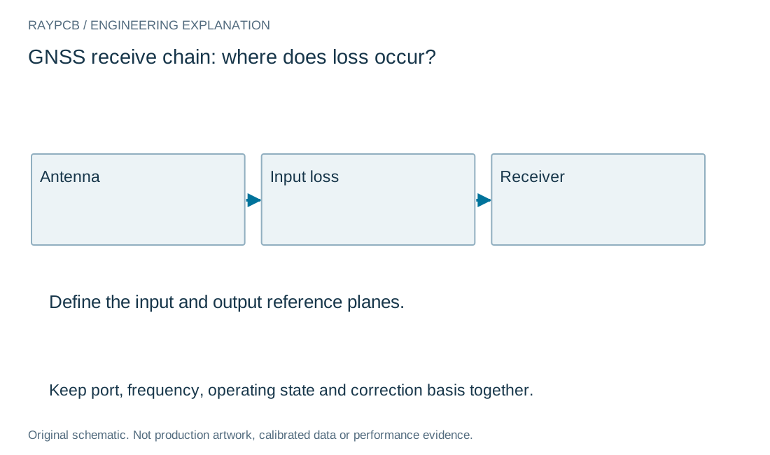
Receiver-chain evidence
| Element | What matters | Do not infer |
|---|---|---|
| Passive input path | Loss, matching and temperature basis | Complete navigation accuracy |
| Active antenna | Supply, gain, noise and interface | Unlimited overload margin |
| Installed product | Interference and physical configuration | Performance from gain alone |
Distinguish useful gain from a complete noise solution
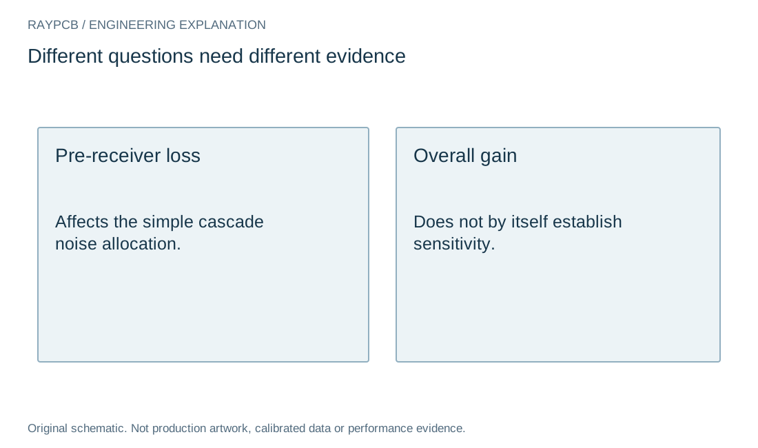
Gain can help overcome losses later in a chain, but it does not restore information already degraded before the first relevant active stage. Review where the losses occur and what source and reference temperatures the noise model assumes. A single total gain number is not enough to describe sensitivity.
An amplifier must also operate appropriately in the presence of unwanted signals. More gain can change overload risk or the levels presented to following stages. Keep filtering, linearity and receiver limits in the review rather than choosing an active antenna solely by the largest gain value in a catalogue.
If several active stages or frequency-selective networks are involved, use a suitable cascade analysis with the actual parameters. The page worksheet intentionally represents only a simple passive loss followed by one receiver. It cannot replace a full model of the antenna, amplifier, cable and receiver environment.
| Review item | What to establish |
|---|---|
| Boundary | Antenna, passive loss, active stages and receiver are distinguished. |
| Noise | Input-loss calculation states matching and temperature assumptions. |
| Interference | Representative product activity is included in evaluation. |
| Handoff | Antenna bias, cable, software and test scope are revision-controlled. |
Passive input loss and receiver noise
Passive input loss and receiver noise
Use the current inputs and keep the assumptions
Enter your own values or use Load example to explore the clearly labeled teaching inputs. The example is not a measured RAYPCB project. Clear for my inputs starts a separate record. Fields identify the units and the physical boundary; missing or unsupported values need correction before a result is generated.
Changing an input invalidates the previous output and disables its download until you generate a new result. A worksheet cannot inspect a board, validate an instrument setup or approve manufacture. Keep its assumptions with any copied number.
Download the current text result if it helps explain a design question. The file stays on your device. Attach or paste it manually when contacting the team; no project information is automatically transferred to the Contact form. Completing this tool is optional.
| Input | What to establish before using it |
|---|---|
| Review reference | Nonconfidential scope or revision. |
| Pre-receiver passive loss · dB | Passive matched network at the standard noise-reference temperature. |
| Receiver noise figure · dB | At the same frequency and reference temperature. |
| Receiver power gain · dB | Gain after the passive input network. No interference or compression model. |
Understand the input-loss worksheet
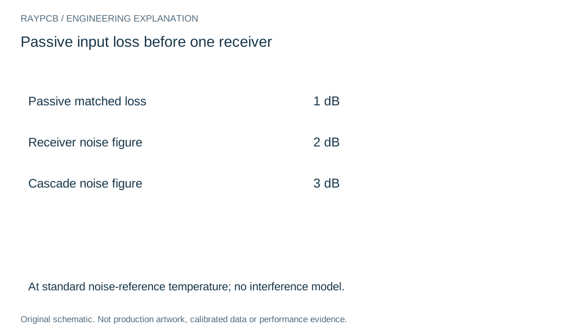
For a matched passive network at the standard noise-reference temperature ahead of a receiver, the simple cascade noise figure in dB equals that passive loss plus the receiver noise figure. The tool also subtracts the same loss from the entered receiver power gain to show the resulting net gain under the chosen boundary.
For example, one decibel of passive input loss and a two-decibel receiver noise figure give a three-decibel cascade noise figure under those assumptions. This is a teaching calculation. It is not a measured RAYPCB receiver, a universal antenna requirement or a prediction of position accuracy.
Keep mismatch, antenna temperature, multiple active stages, frequency variation and interference outside that simple result unless modeled separately. Do not insert a cable loss that is already included in the receiver measurement and count it again. Retain the source of each input so the arithmetic remains auditable.
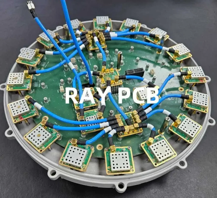
Review active-antenna power and protection
For an active antenna, verify supply voltage, current, bias arrangement and receiver compatibility from the exact product instructions. Identify whether power is provided through the RF connection and how it is separated from the receiver path. The RF and DC requirements must both be satisfied by the actual network.
Consider the intended connection and fault conditions using the device guidance. Protection and filtering components can affect the signal path, while bias choices can affect noise or stability. Keep their models, placement and reference planes visible rather than treating protection as an electrically invisible addition.
Record the complete cable and connector assembly where it is part of the design. The RF cable selection page addresses loss, delay and installed routing. A cable with the same connector names but a different construction should not automatically inherit the previous loss and mechanical assumptions.
Control the product's own interference environment
Map clocks, switching supplies, digital interfaces and nearby transmitters that operate during reception. Include external cables and enclosure connections that can participate in coupling. A receiver evaluated on an otherwise quiet board can behave differently in the final active product.
Use controlled tests to locate an interference mechanism. Retain a baseline, change one relevant activity where practical, and record the response. Do not turn correlation with one operating mode into proof of the sole cause without checking the path and repeatability.
Review any mitigation for its other consequences. A filter, shield or layout change can affect power, RF loss, thermal behavior or mechanical integration. If a power-amplifier path shares the product, keep its operating states in the receiver verification plan instead of testing the receiver only while the transmitter is inactive.
Evaluate the installed antenna and receiver together
Record antenna orientation, ground or mounting surface, housing, cable routing and nearby structures. Keep the physical configuration linked to the electrical and software revisions. A result from an antenna temporarily moved away from the product is a diagnostic configuration, not the final installation.
Use the receiver metrics and test method appropriate to the application and available setup. Preserve the conditions and raw records needed to interpret them. Avoid attributing every difference in a live-sky observation to the PCB when the signal environment and other conditions also changed.
Separate controlled receiver-chain characterization from installed system evaluation. Both can be useful, but their boundaries differ. A valid component or port measurement should not be advertised as complete navigation-product qualification unless the relevant system evidence exists.
Prepare a manufacturing and test handoff
Release the exact receiver and antenna variants, cable, bias network, PCB construction and assembly instructions. Identify alternatives that require RF review. Include relevant orientation, mounting and protection details so the next build reproduces the evaluated configuration.
Define programming, assembly inspection and RF test scope separately. State which results are expected per unit and which belong to design characterization. A request for GNSS assembly should not leave the supplier guessing whether a specific controlled RF screen or an installed-product test is included.
For a RAYPCB enquiry, provide current files, quantity, antenna arrangement and the open construction or test question. The noise worksheet can support the discussion but remains optional. Its downloaded result is local and requires manual attachment; it is not automatic evidence of receiver performance or manufacturability.
Noise allocation is not a receiver field test
The simple input-loss result can reveal why a front-end loss deserves attention, but it does not include the complete antenna noise environment or nearby interference. Keep the calculation separate from controlled receiver measurements and installed-system observations.
If an active antenna or another amplifier is introduced, redraw the cascade with the actual gains and noise parameters. Do not keep applying a two-element worksheet to a different multi-stage system while retaining its original assumptions only in small print.
Standards, source context and limits
Use the current document for the exact selected component, construction and test method. A vendor application note is not a universal fabrication rule. Agree any applicable acceptance standard and edition for the project; these public references do not certify a board or reproduce licensed acceptance criteria.
Photographs are identified as existing site archive context. They do not establish current factory ownership, calibrated results or a customer's product performance. Original diagrams explain the named engineering boundary and are not production artwork or field-solver output.
For fabrication scope and the agreed construction requirements, see PCB manufacturing.