
RAYPCB · ENGINEERING GUIDE
PCB Etchback: Resin Recession, Desmear and Inner-layer Connections
PCB etchback concerns the controlled relationship between resin at a hole wall and exposed inner-layer copper. It is different from etching the circuit pattern on a flat copper surface. Desmear removes drilling-related residue; specified etchback addresses a defined recession and connection geometry. The terms should not be used as interchangeable process guarantees.
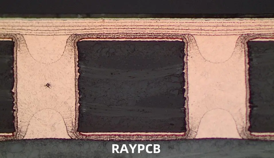
Identify the interface under discussion
A drilled multilayer hole passes resin, reinforcement and copper features. Residual material can interfere with metallization at an inner-layer connection. The preparation process must expose suitable surfaces without creating unacceptable damage or geometry. A drawing should describe the required outcome and applicable acceptance basis rather than naming a chemical treatment as if it alone proves quality.
IPC's public training descriptions recognize dielectric and connection criteria such as etchback and resin recession. Exact acceptance values must come from the agreed specification and revision, not from an unqualified internet table.
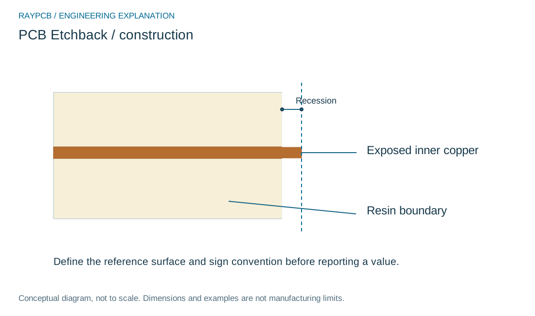
Desmear and etchback answer different questions
Desmear asks whether drilling residue has been removed sufficiently for the intended connection. An etchback requirement asks about a specified geometric relationship at the inner-layer copper and dielectric. A process may address both, but the inspection questions are different.
Do not infer an etchback depth from the fact that a particular cleaning process was used. Materials and process conditions affect the result. The process owner must demonstrate the required outcome on the actual construction.
Read a section with a defined sign convention
The terms positive and negative can become confusing when drawings use different reference directions. Identify the copper edge, resin boundary and measurement axis in the section. State whether the recorded value represents resin recessed from copper or copper recessed relative to resin. A numerical value without that convention can reverse the meaning of a report.
The worksheet accepts a measured recession and a project-defined lower and upper bound in micrometers. It reports whether the entered number lies inside that interval. It does not choose the limits, determine the measurement uncertainty or approve a board.
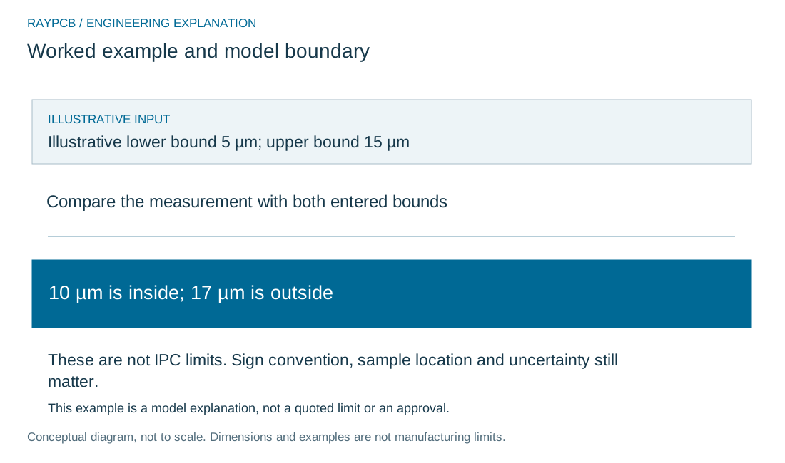
Example: a range check is not process qualification
With illustrative project bounds of 5 to 15 micrometers, an entered measurement of 10 lies inside the range. A value of 17 lies 2 micrometers above the upper bound. These are arithmetic examples, not IPC limits. The result still depends on whether the measurement is representative and taken at the correct interface.
Several section locations may tell different stories. Keep the sample identity, location, preparation method and measurement uncertainty with the record. A favorable single reading does not establish every connection on the panel.
Entered recession range check
Entered recession range check
Use the current inputs and keep the assumptions
Start with the example to understand the units and output, then use Clear for my inputs before entering your project. Example mode stays visibly labeled even if you edit its numbers. The form begins without a result so an illustrative value cannot be mistaken for an approved requirement. Every field must have a valid value; zero is accepted only where it has a meaningful role in the particular model.
Read the input notes before calculating. They identify the physical boundary and what is excluded. Keep the same unit convention across the drawing and worksheet. Changing an input invalidates the previous result and disables its download until you calculate again. This prevents an old number from appearing to describe a revised geometry.
The result is a screening record. A negative margin or an out-of-range condition identifies a question to resolve; a positive margin is not a manufacturing approval. Use the record with the actual drawing, material and project requirement. The model does not load CAD files, inspect images or retrieve private factory data.
Download the current result if it helps the discussion. The text includes the entered inputs, result and limitations. It stays on your device until you choose to attach or share it. Contact is a separate step; this page does not automatically populate the enquiry form or upload a file. Avoid confidential identifiers if you only need an exploratory calculation.
| Input | What to establish before using it |
|---|---|
| Review reference | Use a nonconfidential reference that lets you connect this calculation to the correct drawing revision. |
| Measured recession · micrometers | The tool uses a nonnegative recession magnitude under your stated convention. It does not interpret a micrograph or define the measurement axis. |
| Project lower bound · micrometers | Enter a requirement from the applicable controlled specification. Example values are not IPC limits. |
| Project upper bound · micrometers | Use a bound with the same sign convention and measurement basis. Measurement uncertainty and sample representation need separate review. |
Avoid damage while pursuing a target
More removal is not automatically better. The process must retain suitable material and copper geometry for the completed connection. Review the laminate system, drilling condition, preparation method and later plating together. Changes to the material or hole geometry can require reassessment of the process window.
The panel and hole plating guide explains why copper deposition needs its own evidence. Cleaning and recession measurements cannot substitute for inspection of the resulting plated connection.
Release and enquiry details
Supply the material system, stackup, hole geometry, governing specification and any explicit etchback requirement. If a legacy drawing uses an unclear term, resolve it before manufacture and retain the approved interpretation. Avoid copying a note from a different laminate or product class without checking its applicability.
Is etchback the same as circuit etching? No. Does desmear automatically satisfy every etchback requirement? No. Should a designer prescribe a generic chemical recipe? The preferred handoff is a measurable requirement and agreed evidence, with the qualified process controlled by the manufacturer. Send the relevant cross-section note when requesting review.
Build an evidence chain from geometry to finished connection
Describe the feature at the point where each operation occurs. The initial opening, prepared surface, deposited copper and completed interconnect are different states. A requirement that belongs to the finished connection should not be evaluated only from an image taken before metallization. Likewise, a later electrical pass may not explain the cause of an earlier geometric or interface concern.
Use material identity and process stage when discussing capability. A quoted equipment accuracy, nominal hole diameter or general process name is not the entire manufacturing envelope. The material, local depth, copper structure, pattern density and intended subsequent operations can change the appropriate route. Ask for the construction represented by any example or qualification result rather than extrapolating from a machine brochure.
Make the measurement convention explicit. State the reference surface, axis, diameter plane or recession direction as appropriate. Use one unit system and show conversions where needed. If a result is close to a requirement, consider measurement resolution and uncertainty before drawing a conclusion. More decimal places from a calculator do not make an uncertain physical input more accurate.
Separate process control from customer acceptance. The manufacturer may monitor machine settings, chemistry or intermediate features to maintain a qualified process. The customer acceptance plan may focus on finished geometry, connection integrity and specified evidence. These records are related but not identical. A process setpoint within its control range does not automatically prove every finished feature meets the drawing.
When a defect is investigated, preserve the stage-specific evidence. Identify the sample, location, material and sequence so geometry, preparation and deposition causes can be distinguished. Changing several unrelated variables at once can make the next result harder to interpret. A useful engineering trial states what is being changed, which outcome will be observed and what constitutes a decision to proceed.
For quotation, supply the intended geometry and functional requirements before prescribing a factory recipe. Invite a process proposal where the design remains flexible. If a particular method is mandatory, explain the reason and the evidence needed to show it is suitable. The result should be a controlled route with meaningful checkpoints, not a generic sequence of manufacturing verbs or an unsupported promise that one named process guarantees reliability.
Standards, source context and limits
Use the performance and acceptance documents named in the procurement agreement, including their revisions and any applicable addenda. A design guide explains choices; a product acceptance requirement defines what must be demonstrated. Neither a reference link nor a calculator result is a certification of the board or the supplier. Where a value is contractually important, check the controlled document and agree the measurement method with the responsible parties.
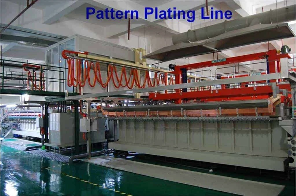
Examples on this page are deliberately labeled and are not advertised RAYPCB limits. Supplier documentation is linked for the specific material or process context it explains. Equipment photographs and cross-section examples show the subject; they are not current production, inspection or qualification records for your order.

