
RAYPCB · ENGINEERING REFERENCE
Arlon 85HP PCB: thermal path & build review
Review filled polyimide for a demanding multilayer construction. Separate material thermal conductivity, the complete heat path and the verification needed for a production build.
Original engineering guidance · References checked September 28, 2026
What is an Arlon 85HP PCB?
An Arlon 85HP PCB is a rigid circuit-board construction using the specified 85HP polyimide laminate and approved prepreg system. It belongs to Arlon Electronic Materials' polyimide range; it is not an Arlon PTFE microwave laminate and it is not a flexible polyimide film. The buying task is to connect its material properties with a real multilayer construction, thermal path and qualification plan.
The official 85HP product page describes a polyimide resin system with proprietary micro-fine fillers. The 85HP v1.4 data sheet lists typical thermal conductivity of 0.5 W/(m·K), Tg of at least 250°C and total Z expansion below 1% over 50–260°C. Those are material reference properties, not a board operating-temperature rating, a thermal solution or a guarantee of plated-hole life.
Evaluate the reason for choosing filled polyimide
Start by stating which requirement is driving the material discussion. A thick multilayer with a dense plated-hole population presents different concerns from a board whose main challenge is moving heat to an enclosure. Both might prompt an 85HP review, but they require different evidence. Ask whether the problem concerns dielectric movement, hole-wall reliability, local resin integrity, a thermal path, or several of these together.
If a current design uses Arlon 85N, compare the proposed 85HP construction deliberately. A similar Tg is not sufficient evidence of equivalence. Preserve the glass and resin assignment, copper pattern, dielectric thickness and processing basis in the comparison. Identify which dimensions and properties are changing and which qualification results can legitimately be reused. Avoid describing the change as a purchasing substitution until the engineering decision is complete.
| Design concern | Useful input | Evidence to discuss |
|---|---|---|
| Dense plated holes | Hole spans, prepared drill, finished bore and board thickness | Representative hole preparation and cross-section requirements |
| Thermal conduction | Actual heat path, thickness, area and directional conductivity | Thermal model and installed-condition measurements |
| Local resin behavior | Copper density, clearances and construction | Lamination and specimen review for the specified build |
| Repeated thermal exposure | Assembly history and service requirements | Agreed conditioning and acceptance criteria |
Calculate one dielectric thermal resistance
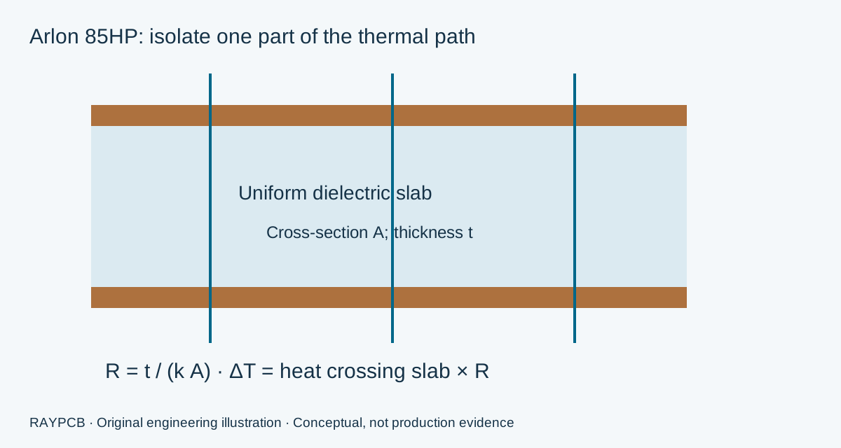
This worksheet answers a deliberately narrow question: what resistance would a uniform dielectric slab present to one-dimensional steady conduction? Enter the path thickness, conducting area, applicable directional conductivity and the heat actually crossing that slab. The geometry is more important than a generic board outline; most of the board area may not participate uniformly in a local heat path.
RAYPCB ENGINEERING
High Performance MaterialsArlon 85HP dielectric thermal-path worksheet
Loading Arlon 85HP dielectric thermal-path worksheet…
The example conductivity of 0.5 W/(m·K) comes from the cited material sheet, but its applicability to the selected construction and heat-flow direction still needs confirmation. Other example inputs are hypothetical. The result is a temperature difference across the modeled dielectric only. It is not junction temperature, a component rating, or a predicted board temperature in an enclosure.
A conductivity value is not a thermal design
Consider an illustrative 0.5 mm dielectric path with a uniform conducting area of 100 mm² and conductivity of 0.5 W/(m·K). Converting the geometry to SI units gives R = 0.0005 / (0.5 × 0.0001) = 10 K/W. If 2 W crosses that path, the calculated temperature difference is 20 K. Doubling the area halves this simplified resistance; doubling the thickness doubles it.
The tool does not assume that all heat from a component crosses the selected slab. Heat can spread through copper and leave through other paths, while interfaces and contacts can add resistance. A thermal via array creates a different geometry that this uniform-slab calculation does not resolve. Use the number as a transparent component of a thermal discussion, then develop the complete model for the actual construction and installation.
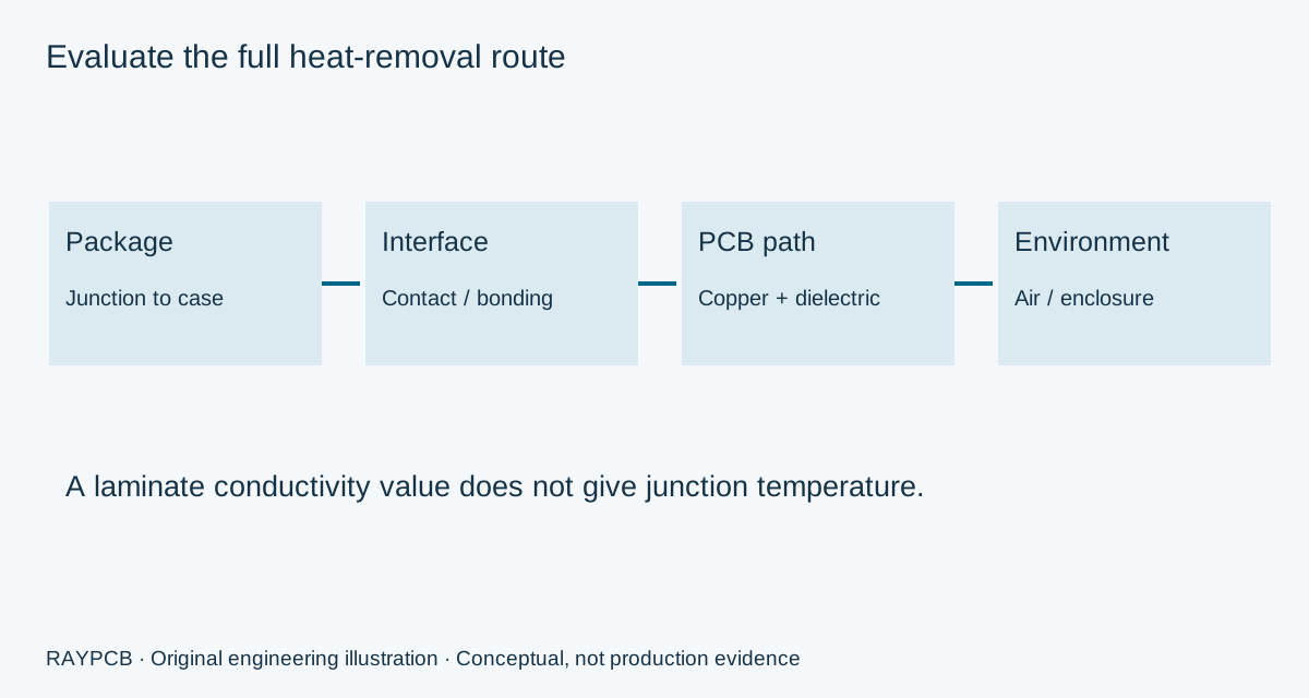
If the result seems too large, first inspect the assumed path rather than substituting a larger conductivity number. Confirm the area, direction and thickness. Determine whether a plane, spreader, chassis connection or a different construction controls the design. For designs centered on heat spreading through a metal substrate, the metal-core PCB guide addresses another material architecture. It is a separate route, not an automatic replacement for a multilayer 85HP board.
Define the filled-polyimide multilayer precisely
A useful drawing separates finished copper, dielectric cores and complete pressed bondlines. Identify copper-heavy areas and unusual local clearances. A list of glass styles without resin content or pressed-thickness requirements cannot fully describe the stack. The fabricator needs the actual copper distribution to review resin demand and dimensional control, especially when the board contains dense interconnections and large power regions together.
Specify hole dimensions using clear reference terms. Finished bore, prepared drill and tool size are different quantities. A board-thickness-to-hole ratio is meaningful only when the denominator is stated, and it does not predict drill quality or copper deposition. Mark the critical hole groups and their spans so the proposed process and acceptance evidence address the right features. Do not use a single blanket ratio as proof that all holes share the same risk.
Electrical requirements remain relevant even when thermal behavior drives the material choice. Record the target impedance, reference planes and any critical propagation paths. Do not turn a low-frequency dielectric property into a GHz design parameter without appropriate data. Material selection can change the mechanical and electrical model at the same time; both must remain linked to the released stackup.
Review material condition, processing and finished evidence
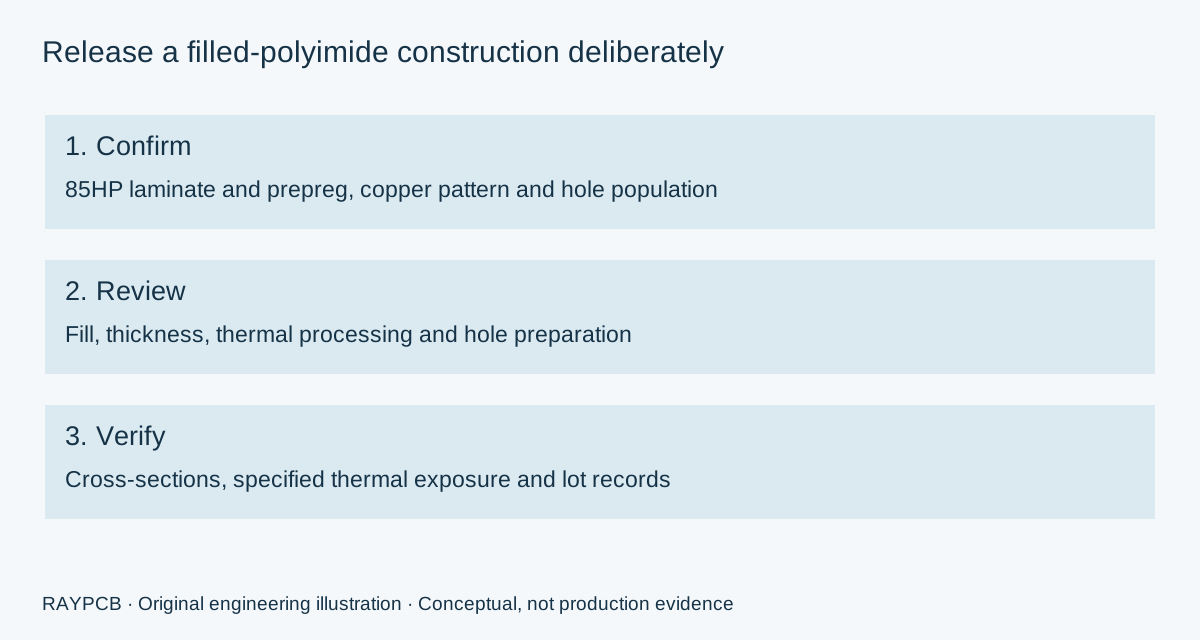
The 85HP processing guide provides manufacturer guidance for process development. The production route still needs to be qualified for the selected materials, panel, copper pattern and equipment. A web page should not convert a starting recommendation into a universal bake or press recipe. The appropriate question is how the approved process preserves the finished requirements of this board.
Material storage, exposure history and handling should be controlled through fabrication and assembly. Before requesting a bake, identify the material state, finish, populated or bare-board condition and the governing process documentation. An improvised thermal treatment can affect more than moisture. Record the responsible process owner and the evidence required before material moves into the next operation.
For lamination and drilling, define the representative construction and inspection points. For thermal qualification, define exposure, sample preparation and the criterion being evaluated. Connectivity testing is valuable but does not replace a thermal reliability study. A cross-section of one specimen also has a specific sampling scope. Keep these distinctions visible in the quotation so the customer can decide which evidence the application actually needs.

High reliability needs a defined evidence chain
An industrial sensor near a hot process and a long-lived control board can both raise questions about thermal stability, but their installed environments differ. Describe local temperatures, gradients, mounting, vibration and the expected operating history. A material datasheet does not account for nearby hot components, heat trapped by an enclosure or stress from a mounting arrangement. Those belong in the product engineering assessment.
A high-reliability purchase should name the board requirements and the required records. If an IPC material slash sheet is specified, confirm the current controlled document, exact product and applicable evidence. Do not carry a material supplier's recognition across to RAYPCB or the final device as an implied certification. Discuss the drawing, construction and acceptance plan with PCB Manufacturing before committing a release to production.
Budget the process and evidence, not only the laminate
Material purchasing increments, usable panel positions, tooling, fabrication complexity and qualification scope affect an 85HP project budget. A quotation for a routine repeat build should not be compared directly with one that includes new cross-sections, thermal qualification or dedicated fixtures. Separate one-time engineering from recurring costs and state whether the panel allowance already includes the special processing being discussed.
RAYPCB ENGINEERING
High Performance MaterialsArlon 85HP documented lot budget
Loading Arlon 85HP documented lot budget…
The budget worksheet shares the tested panel-and-lot arithmetic used by the material tools, with an 85HP scope and a separate thermal/hole qualification allowance. It uses no FR-4 market rate or invented material premium. Inputs are blank until you supply them or deliberately load the illustrative example. The output is an uncalibrated planning estimate and does not confirm stock, lead time, manufacturability or a binding price.
When requesting a quotation, include the released fabrication files, stackup, quantity, copper and hole requirements, intended delivery date and inspection scope. Identify thermal qualification as a named deliverable with its acceptance source. A local brief can accompany these files, but neither worksheet uploads the attachments or transfers them into Contact. Use the direct enquiry route whenever the construction needs discussion before any numerical estimate is useful.
Arlon 85HP design and procurement questions
Does higher conductivity eliminate thermal vias?
No. The useful heat path depends on geometry, copper, packages, interfaces and installation. A laminate property alone cannot decide whether vias, planes or a spreader are necessary. Model the complete route and verify the intended operating conditions.
Can 85HP replace 85N without a design review?
Treat it as a controlled material change. Compare the actual laminate/prepreg construction, electrical model, process requirements and required qualification. Similar temperature headlines are not substitution approval, and previous test evidence may not cover the new construction.
Does the worksheet calculate maximum operating temperature?
It calculates only resistance and temperature difference across an entered uniform slab. It does not solve the surrounding thermal system, long-term material aging, component limits or product safety requirements. Those require an application-specific assessment.
Where should I start if the material is not fixed?
Use the Arlon material-family guide to separate rigid polyimide from RF laminate families. Then send the construction and the problem driving material selection. A focused review can identify which missing evidence prevents a useful comparison.
Discuss the exact material and construction
Send the board revision, construction, quantity and the material, electrical or fabrication question you need reviewed. Identify unresolved requirements so the response can address them.
Send requirements for reviewOptional: attach the downloaded worksheet manually. This guidance does not certify a design, approve a shipment or replace the applicable authorized standards.